Publisher’s version / Version de l'éditeur:
Proceedings of the 24th International Congress on Sound and Vibration, 2017-07-27
READ THESE TERMS AND CONDITIONS CAREFULLY BEFORE USING THIS WEBSITE.
https://nrc-publications.canada.ca/eng/copyright
Vous avez des questions? Nous pouvons vous aider. Pour communiquer directement avec un auteur, consultez la première page de la revue dans laquelle son article a été publié afin de trouver ses coordonnées. Si vous n’arrivez pas à les repérer, communiquez avec nous à [email protected].
Questions? Contact the NRC Publications Archive team at
[email protected]. If you wish to email the authors directly, please see the first page of the publication for their contact information.
NRC Publications Archive
Archives des publications du CNRC
This publication could be one of several versions: author’s original, accepted manuscript or the publisher’s version. / La version de cette publication peut être l’une des suivantes : la version prépublication de l’auteur, la version acceptée du manuscrit ou la version de l’éditeur.
Access and use of this website and the material on it are subject to the Terms and Conditions set forth at Radiation efficiency of metal stud plaster-board walls
Schneider, Martin; Zeitler, Berndt
https://publications-cnrc.canada.ca/fra/droits
L’accès à ce site Web et l’utilisation de son contenu sont assujettis aux conditions présentées dans le site
LISEZ CES CONDITIONS ATTENTIVEMENT AVANT D’UTILISER CE SITE WEB.
NRC Publications Record / Notice d'Archives des publications de CNRC: https://nrc-publications.canada.ca/eng/view/object/?id=5c3a703a-70ab-4754-8912-e32c73478d9e https://publications-cnrc.canada.ca/fra/voir/objet/?id=5c3a703a-70ab-4754-8912-e32c73478d9e
BOARD WALLS
Martin Schneider and Berndt Zeitler
Stuttgart University of Applied Science, Schellingstr. 21, D-70147Stuttgart email: [email protected], [email protected]
The radiation efficiency of different plasterboard walls was determined through measurements in the direct sound transmission facilities at the University of Applied Science in Stuttgart. The ra- diation efficiency was determined using airborne sound excitation in the source room. The veloc- ity on the plasterboard on the receiving room side was measured using accelerometers and the radiated sound power was calculated from the sound pressure level in the diffuse receiving room. In this study it was identified that the radiation efficiency of identical boards depends strongly on the construction of the wall (shaft wall, single stud wall, double stud wall) and in the low fre- quency range also on the mass-spring-mass resonance frequency of the double walls. The typical shape of the radiation factor, going from high to low frequencies, shows a decrease below the critical frequency of the plasterboard (at approx. 3 kHz) down to approx. -15 dB in the frequency range from 1250 Hz to 250 Hz. Below 250 Hz the radiation factor increases again, almost up to 0 dB in the frequency region close to the resonance frequency of the mass-spring-mass resonance. Why there is this increase of the radiation efficiency at low frequencies is explained through cal- culations that are related to the stiffness of the complete construction.
Keywords: (radiation efficiency, plasterboard wall)
1. Introduction
Plasterboard walls with metal studs are common assemblies in residential and in office buildings. These lightweight walls provide high sound insulation and are therefore used to separate rooms where acoustical comfort is desired. To achieve the different requirements on sound insulation a variety of assemblies are available on the market. These systems may have single, double or triple layers of plasterboard on each side with possibly different thicknesses and/or densities. These double leaf as- semblies consists either one row of common studs or two rows of separated studs on which the plas- terboard is fastened with screws. Different widths of these steel studs provides a variety of cavity depths, which is usually filled with absorbing material. All of these construction parameters, includ- ing the thickness and type of absorption material, influence the acoustical behaviour more or less significantly. Furthermore, the spacing of the studs, the distance of the screws, and even the location of the screws on the studs influence the sound insulation of the system. Last but not least, where and how the wall assembly was constructed - in a building or in a laboratory, especially with respect to the boundary conditions, - and the quality of workmanship, may have an influence on the acoustical performance.
In 2012 a project to measure the sound reduction index (SRI) of metal single stud, double stud, and shaft wall constructions using novel plasterboard was initiated by plasterboard company at the Applied University of Sciences Stuttgart (HFT). One goal of the study was to investigate the influence of the boundary conditions on the SRI and the repeatability of SRI. Furthermore, velocity levels and
ICSV24, London, 23-27 July 2017
2 ICSV24, London, 23-27 July 2017
structural reverberation times were collected and a modal analysis of the wall was conducted. Thus, it was possible to improve the understanding of the acoustics of these plasterboard walls. The follow- ing paper will illustrate these experimental findings and will graphically present the results. The ra- diation efficiency of these walls, as an important acoustic quantity, is discussed in detail. The meas- ured radiation efficiency is compared with theoretical values of single plasterboards and plasterboard walls.
All measurements on the metal stud walls were done in the wall test stand of the HFT Stuttgart according to ISO 10140-2 [1]. The walls were constructed with a stud spacing of 625 mm into a lower and an upper metal U-channel. The U-channels were fixed with screws to the lower and upper frame of the test stand as well as to outer left and right studs. If not otherwise stated the U-channels or the outer metal studs were separated from the test stand concrete frame by a sealing tape, which was additionally sealed with acrylic compound. The applied plasterboards have a size of 12.5 mm x 3000 mm x 1250 mm to fit into the height of the aperture. The plasterboards were screwed to the metal studs with an average screw spacing of 350 mm. The surface mass of the plasterboard is m' = 13kg/m². A gap of approx. 10 mm between plasterboards and test stand was ensured to prevent con- tact. The joint between the plasterboard and the concrete frame, as well as the screws and the joints between the boards of the test stand, were filled with plaster.
2. Theory
The radiation efficiency of plates strongly depends on their critical frequency fc. The calculation
of the critical frequency fc,p of a homogenous plate is straight forward [2], whereas for plasterboard
walls with coupled plates the bending stiffness changes and hence a second critical frequency fc,w for
the wall appears. This value is derived and used to calculate the radiation efficiency for plasterboards walls in the frequency range below the mass-spring-mass-resonance frequency f0 of the wall.
2.1 Critical frequency
The critical frequency fc of an infinite plate can be calculated from the mass per unit area of the
plate m’ and the bending stiffness per unit area B’ respectively according to Eq. (1).
��� �′
�� = �� √
�′ . (1)
For homogeneous plates the critical frequency fc can be related to the longitudinal wave speed cL
and the thickness t of the plate:
�� = ���√� � 1 (2) ���
Considering two identical plates, both with the thickness t, separated by the distance d, the bending stiffness of a double leaf wall can be calculated using the inertia and an effective bending stiffness of the full wall. Hence, the critical frequency of the complete wall becomes:
�� = ���√� � √� ��√(��+�)�−�� (3) 2.2 Radiation Efficiency
The radiation efficiency is a dimensionless quantity describing the ratio of the sound power radiated by the structure of interest to that of a piston having the same mean-square velocity as the structure of interest. According to Hopkins [2] the frequency averaged radiation efficiency of a plate can be calculated in one-third octave bands for three different frequency ranges: in the frequency range below, at and above the critical frequency fc with the following equations:
√ � = � with: � = �� � (4) for f < fc �+� �� � [�� ( ) + ] [� � − �−�(� � − �)] (5) for f = fc �����√��−� �−� ��−� �� � �� �� � ≈ (�. � − �.���� ) √�√� (6) and for f > fc �� � � = � √�−�� (7)
With L1 as the smaller and L2 as the larger plate dimension, U the perimeter of the plate and S the
area. CBC and COB are equal to one or two depending on the boundary conditions.
2.3 Mass-Spring-Mass resonance frequency f0
The mass-spring-mass resonance frequency of a plasterboard wall is determined by the mass per unit area m’ of the two plates and the stiffness per unit area s’ of the spring:
� = √�′ � �′�
+ � �′�
(8)
For cavities filled with fibrous materials isothermal compression (= 1.0) is a reasonable assump- tion and the stiffness s’ depends on the depths d of the cavity and is given by:
�′ = ����
�
For 20°C the resonance frequency f0 is then given by:
(9) � � ��= ��√ ( + � )[Hz] (10) � �′� �′�
3. Vibrational behaviour / Model analysis
The vibration behaviour of a partition of the double wall at low frequencies was investigated using experimental modal analysis. The wall was constructed of two layers of 12.5 mm plasterboard (m’ = 12.8 kg/m²), fastened to 50 mm thick metal studs. The cavity was filled with 40 mm thick min- eral wool. The partition was 2.72 m high and 4.12 m wide and was constructed inside a test rig for measuring sound insulation according to ISO 10140-2 [2]. For the modal analysis approximately half of the partition was used. The modal analysis grid spacing was 250 mm resulting in a theoretical resolution of 4 measurement points per wavelength at the highest frequency of interest (43 Hz for the single plasterboard and 681 Hz for the double wall).
ICSV24, London, 23-27 July 2017
4 ICSV24, London, 23-27 July 2017
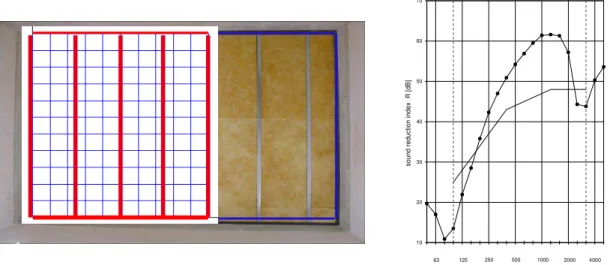
70 60 50 40 30 20 10 63 125 250 500 1000 2000 4000 frequency f [Hz]
Figure 1: picture on left: metal stud frame wall in the laboratory, with indicated modal analysis grid and stud positions. Graph on right: measured SRI of the wall
The grid consists of 264 (2 x 11 x 12) points. Following the reciprocal method of modal analysis, a fixed reference accelerometer was placed in the lower corner of the front plate (left plate in figure 4) and a moving impact hammer was used to measure the individual transfer functions between the excitation points and the reference accelerometer. Four of the mode shapes between 18 Hz and 458 Hz are shown in Figure 2. The two plates are strongly coupled below the mass-spring-mass res- onance frequency (f0 = 80 Hz from fig. 1; f0 = 90 Hz from eq. 10) by the stiffness of the air cavity an
move totally in phase.
Figure 2: Four vibrational patterns of a metal stud wall. From left to right with increasing frequency: A-vi- bration pattern at f1 = 18 Hz, B-vibration pattern at f2=34Hz still below resonance frequency, C-vibration pat-
tern near resonance at f3 = 84 Hz, and D- well above the resonance frequency at f4 = 458 Hz.
The lowest (theoretical) eigenmode of the wall is below 10 Hz and could not be detected with the measurements. Yet, the second eigenmode at 18 Hz, a mode at 34 Hz, a mode close to resonance at 86 Hz, and one well above resonance 458 Hz, were captured, as shown in Figure 2 from left to right. The locations of the studs are not evident in the vibration pattern of the wall, which indicates that the studs do not restrict the motion of the plasterboards significantly and the stiffness of the air between the plates determines the coupling in the frequency region at and below the resonance frequency. The modal behaviour and that the two plates more in phase can be clearly seen in the two modes below the mass-spring-mass resonance f0 at 80 Hz (A & B in Figure 2). Above f0 however (C & D), the
modal vibration pattern is difficult to detect and the relative phase of the plates are no longer visible due to the small wavelength on the plasterboards. At frequencies well above the resonance frequency f0 (D) only the motion on the excited plate (left) is visible, which indicates that the second (right)
A B C D sound reduction in d e x R [d B ]
plate is well decoupled from the plate. At low frequencies there is no motion of the edges of the plates, whereas at higher frequencies a slight motion of the plasterboards can be observed.
4. Radiation efficiency
As per definition above the radiation efficiency of plates far above the critical frequency fc is
unity. This is due to the fact that at frequencies above the critical frequency the wavelength in air becomes very small compared to the wavelength on the plate, so the plate vibration looks like a piston to the air waves. The radiation factor, L10 log is the correspondent logarithmic value to the
radiation efficiency. This quantity can be measured according to eq. (11), when the sound power radiated from a wall is calculated from the average velocity level Lv (dB ref. 5x10⁻⁸ m/s) on the wall with the area S, the sound pressure level Lp and the equivalent absorption area A in the receiving room.
L10 lgLp Lv 10 lg A 10 lg S 6dB (11)
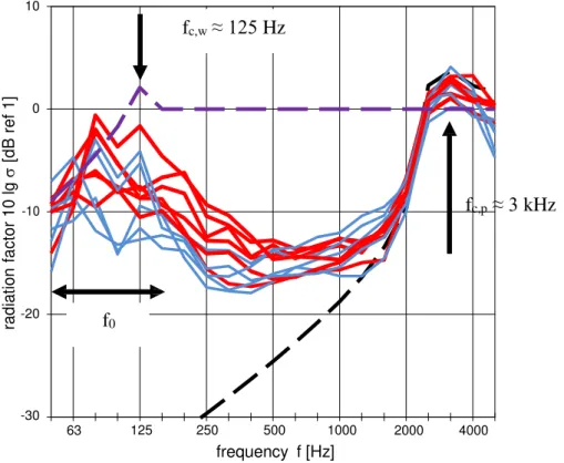
In Figure 3 the radiation factor Lis shown for different metal stud walls excited with airborne sound. Note that as the resulting vibration pattern of the wall is dependent on the type of excitation (airborne or structure-borne), so is the radiation efficiency. The critical frequency fc,p of the 12.5 mm
plasterboard is at about 3 kHz. The critical frequency fc,w of the complete walls depend on the depth
d of the cavity and the mass of the plasterboard and is in the range of 60 Hz – 300 Hz.
10 fc,w ≈ 125 Hz 0 -10 fc,p ≈ 3 kHz -20 f0 -30 63 125 250 500 1000 2000 4000 frequency f [Hz]
Figure 3: Radiation factor of different metal stud walls. The continuous lines represent different double walls with single (red) and double (blue) layers of 12.5 mm plasterboard. The black dashed line corresponds to a calculated radiation efficiency fc,p of a single plasterboard according to eqs. (5)-(7). The purple dashed line
shows the calculated radiation efficiency of a double wall where the stiffness is determined by two coupled plasterboards spaced 0.1 m (stud width) using to eq. (3).
In the high frequency range near the critical frequency (fc,p ≈ 3 kHz) the radiation efficiency of the
double walls is determined by the radiation efficiency of the plasterboard layer. At the critical fre- quency fc,p the radiation factor is about 1 dB – 3 dB and going to lower frequencies drops to – 15 dB
rad iat ion f a c to r 10 lg [ d B r ef 1]
ICSV24, London, 23-27 July 2017
by approx. 1 kHz. Between 1 kHz and the critical frequency all the measured radiation factors are very close together and fit well with the calculated value of a single plasterboard even when the double walls have two layers of plasterboard on each side (blue lines in Fig. 3).
In the frequency range from 1 kHz to 400 Hz the radiation efficiency stays nearly constant at a level of approx. -15 dB, in contrast to the further decrease of the calculated radiation factor of the plasterboard. At frequencies below 400 Hz the radiation factor rises again to a value close to 0dB. Here the walls with two plasterboards on each side (blue lines) have the lower radiation factor due to the lower mass-spring mass resonance f0.
For most walls the radiation factor drops again at very low frequencies. At frequency near the mass-spring-mass resonance of the double wall (50 Hz – 100 Hz) the radiation efficiency is deter- mined by the mass-spring-mass resonance of the two plates coupled by the stiffness of the air between the plates. Below the resonance frequency f0 the two plates vibrate in phase and the radiation effi-
ciency of the wall is determined by the vibration of the coupled panels.
The steel studs in this investigation were chosen between 5 mm and 15 mm deep. Combined with the 12.5 mm plasterboard panels this leads to mass-spring-mass resonance frequencies between 60 Hz and 140 Hz. As the boards are coupled by the air stiffness below the mass-spring-mass resonance, the radiation efficiency rises to a maximum at the critical frequency fc,w of the wall and drops for fre-
quencies below this “second” critical frequency. The calculated radiation efficiency of a wall of two plasterboards separated 10 mm give a radiation factor which also drops below this critical frequency. The vibrational behaviour of the wall visualized for some frequencies in Fig. 2 (in-phase vibration with equal amplitude of both plasterboards below the resonance frequency f0, independent vibration
well above the resonance frequency f0) can be found in the spectrum of the radiation factor of the
construction. In the frequency range above the resonance frequency f0 of the double-wall construction
and well below the critical frequency of the single plasterboard panel fc,p, the radiation factor seems
to have a cross over range were the two theoretical values approach.
10 fc,w ≈ 125 Hz 0 -10 fc,p ≈ 3 kHz -20 f0 -30 63 125 250 500 1000 2000 4000 frequency f [Hz]
Figure 4: Radiation factor of different types of metal stud walls. The blue continuous line is the average with indicated standard deviation of the measured double walls with common studs shown in fig. 3. The black line
(squares) is the radiation factor measured on a double wall with separated studs. The green line is the radia- tion factor measured on a shaft wall (single panel). The red dashed line shows the calculated radiation effi-
ciency of a double wall where the stiffness is determined by two coupled plasterboards spaced 0.1 m.
6 ICSV24, London, 23-27 July 2017
rad iat ion f a c to r 10 lg [ d B r ef 1]
The wall with two separated studs (two single layers of plasterboard on two separated metal studs, green line) has no rigid connection and therefore is excited only by airborne sound. The shaft wall (single plasterboard on metal studs, green line in fig. 4) is also only excited by airborne sound. Near the critical frequency of the plasterboard (fc,p), the radiation factors of these two walls (black and
green line in Fig. 4) are nearly identical to each other and together are well above the radiation factor of the walls with the common studs. Below 1 kHz the radiation factor of the double wall decreases to approx. -20 dB at 315 Hz, whereas the radiation factor of the shaft wall stays at a level of -5 dB. The radiation factor of the shaft wall is far above the other measured radiation efficiencies and the ex- pected value. This could be due to the direct excitation of the metal studs and the plasterboard by the diffuse sound field in the source room.
Small differences in the frequency range of 400 Hz - 2 kHz can be seen between the wall with separated studs and the common studs. The differences could be caused by the type of excitation of the plasterboard. For separated studs the plasterboard on the receiving side is excited only by airborne sound, whereas for the double walls excitation is by the structural connection of the screws in the metal studs. These differences due to the excitation type are also observed for the shaft wall in the frequency range of 1 kHz to 2 kHz. Below 1 kHz the radiation efficiency of the shaft wall increases due to the direct airborne excitation of the shaft wall with the metal studs as stiffeners.
5. Summary
The radiation factor of double leaf plasterboard metal stud walls was measured in a test stand using airborne excitation. The measured radiation factor in the high frequency range is determined by the vibration of the outer layer of the plasterboard. The radiation factor in the low frequency range is determined by the vibration of the complete wall. Similar to the effects determining the sound insu- lation in the frequency range below mass-spring-mass resonance f0 the plasterboards are coupled
together by the stiffness of the air between the two plates and vibrate in phase as a “homogeneous” plate. An “effective” critical frequency of the wall fc,w for these vibrations can be calculated and
explain the increase in radiation efficiency in this lower frequency range. Differences in the radiation efficiencies between plasterboard walls with one common and two separated studs due to the different types of excitation are also observed. The airborne excitation of the wall with the separated studs leads to an increased radiation efficiency compared to the structural excitation via the common stud in the frequency region between 500 Hz and 2 kHz.
The authors like to thank Siniat GmbH Frankfurt for the support of the assembly of the plaster- board walls.
REFERENCES
1 ISO 10140-2, Acoustics –Laboratory measurement of sound insulation of building elements –Part 2: Measurement of airborne sound insulation (ISO 10140-2:2010); German version EN ISO 10140-2:2010. 2 Hopkins, C.: Sound Insulation, Elsevier, (2007).