Publisher’s version / Version de l'éditeur:
Vous avez des questions? Nous pouvons vous aider. Pour communiquer directement avec un auteur, consultez la première page de la revue dans laquelle son article a été publié afin de trouver ses coordonnées. Si vous n’arrivez pas à les repérer, communiquez avec nous à [email protected].
Questions? Contact the NRC Publications Archive team at
[email protected]. If you wish to email the authors directly, please see the first page of the publication for their contact information.
https://publications-cnrc.canada.ca/fra/droits
L’accès à ce site Web et l’utilisation de son contenu sont assujettis aux conditions présentées dans le site LISEZ CES CONDITIONS ATTENTIVEMENT AVANT D’UTILISER CE SITE WEB.
Advances in Materials Science and Engineering, 2019, pp. 1-23, 2019-04-01
READ THESE TERMS AND CONDITIONS CAREFULLY BEFORE USING THIS WEBSITE. https://nrc-publications.canada.ca/eng/copyright
NRC Publications Archive Record / Notice des Archives des publications du CNRC :
https://nrc-publications.canada.ca/eng/view/object/?id=58326d06-b40f-4ff5-a1ec-8baf7b6e6e3f
https://publications-cnrc.canada.ca/fra/voir/objet/?id=58326d06-b40f-4ff5-a1ec-8baf7b6e6e3f
Archives des publications du CNRC
This publication could be one of several versions: author’s original, accepted manuscript or the publisher’s version. / La version de cette publication peut être l’une des suivantes : la version prépublication de l’auteur, la version acceptée du manuscrit ou la version de l’éditeur.
For the publisher’s version, please access the DOI link below./ Pour consulter la version de l’éditeur, utilisez le lien DOI ci-dessous.
https://doi.org/10.1155/2019/3979471
Access and use of this website and the material on it are subject to the Terms and Conditions set forth at
Titanium alloy repair with wire-feed electron beam additive
manufacturing technology
Wanjara, P.; Watanabe, K.; de Formanoir, C.; Yang, Q.; Bescond, C.; Godet,
S.; Brochu, M.; Nezaki, K.; Gholipour, J.; Patnaik, P.
Research Article
Titanium Alloy Repair with Wire-Feed Electron Beam Additive
Manufacturing Technology
P. Wanjara ,
1K. Watanabe,
2C. de Formanoir,
3Q. Yang,
1C. Bescond,
1S. Godet,
3M. Brochu,
4K. Nezaki,
2J. Gholipour,
1and P. Patnaik
11National Research Council Canada, Aerospace, Montreal H3T 2B2, Canada 2IHI Corporation, Yokohama-shi, Kanagawa 235-8501, Japan
34MAT, Universit´e Libre de Bruxelles, 50 Avenue F.D. Roosevelt, 1050 Bruxelles, Belgium 4McGill University, Department of Materials Engineering, Montreal H3A 0C5, Canada
Correspondence should be addressed to P. Wanjara; [email protected] Received 13 November 2018; Accepted 13 January 2019; Published 1 April 2019 Academic Editor: Paolo Ferro
Copyright © 2019 National Research Council of Canada. This is an open access article distributed under the Creative Commons Attribution License, which permits unrestricted use, distribution, and reproduction in any medium, provided the original work is properly cited.
Wire feeding can be combined with different heat sources, for example, arc, laser, and electron beam, to enable additive manufacturing and repair of metallic materials. In the case of titanium alloys, the vacuum operational environment of electron beam systems prevents atmospheric contamination during high-temperature processing and ensures high performance and reliability of additively manufactured or repaired components. In the present work, the feasibility of developing a repair process that emulates refurbishing an “extensively eroded” fan blade leading edge using wire-feed electron beam additive manufacturing technology was examined. The integrity of the Ti6Al4V wall structure deposited on a 3 mm thick Ti6Al4V substrate was verified using X-ray microcomputed tomography with a three-dimensional reconstruction. To understand the geometrical distortion in the substrate, three-dimensional displacement mapping with digital image correlation was undertaken after refurbishment and postdeposition stress relief heat treatment. Other characteristics of the repair were examined by assessing the macro- and microstructure, residual stresses, microhardness, tensile and fatigue properties, and static and dynamic failure mechanisms.
1. Introduction
Fleet managers and operators in the aerospace sector, faced with ever-increasing demands to lower operational costs, have sought repair and rejuvenation solutions to maximize the utilization, availability, and lifespan of their assets. For in-stance, in commercial and military gas turbine aeroengines, the commonly applied repair scheme for refurbishing ex-tensively eroded first stage titanium alloy fan blades involves sequential operations of (1) inspecting and removing the foreign object debris and damage, (2) preparation of the repair patch by stamping, rolling, or forging, (3) prerepair coating removal and cleaning, (4) fan blade and patch positioning, alignment, and fixturing, (5) fusion welding of the repair patch using tungsten inert gas, hot wire metal inert gas, laser, and/or EB welding, (6) postweld heat treatment, (7) final machining, and (8) nondestructive inspection [1, 2]. However, this repair
procedure can involve long turnaround times and high costs due to material preparation of the repair patch, prerepair setup, and postrepair machining. Consequently, there has been high interest to deliberate alternate solutions based on advanced AM technologies [3–5] that enable automated weld bead build-up (deposition) to refurbish severely foreign object-damaged titanium alloy components.
Consisting of a suite of emerging technologies [6], AM in the aerospace sector has involved two main types of processes, namely PBF and DED. Currently, powder bed platforms are well suited for low-volume manufacturing of small replace-ment parts with medium- to high-complexity geometry and a procedure for Ti6Al4V using EB melting has been reported in [7]. By contrast, DED technologies have evolved from welding based platforms, traditionally designed for joining, cladding, coating, and repair [8–11], that have been integrated with computer-aided design software and, increasingly, also with
in-line vision and metrology inspection systems. These AM processes have evolved rapidly and matured sufficiently to deliberate retrofits and repairs for a broad range of structural metal alloys and functional applications.
However, numerous challenges that presently exist limit the consideration of AM, especially those related to metal-based platforms, as a reliable technology for the aerospace industry. Potential areas of research and development that need to be addressed to ascend AM technologies towards widespread production, especially for critical aerospace applications, include improved understanding of the pro-cessing influences on the materials and properties, in-process monitoring and control systems for early flaw de-tection, comprehensive coupling of precision and resolution capabilities of the diverse technologies to assure re-producibility and reliability of the component, and tools and software enabling design freedom alongside the material performance data [12].
In the present research, the wire-fed EBAM platform was selected to evaluate the feasibility of repairing Ti6Al4V aer-oengine fan blades. Often referred to as EB3F [13, 14], electron beam free-forming [15–17], and electron beam direct manufacturing [18], the EBAM process has been the tech-nology considered for numerous studies on depositing Ti6Al4V [18–26]. Previously, the influence of the EBAM process on distortion of a flat Ti6Al4V plate was reported in [27], but deposition on a narrow (3 mm wide) geometry, emulating a fan blade configuration, has not been considered. From a repair perspective, distortion during AM repair (of especially heavily damaged sections) can affect the geometrical characteristics, as well as the structural integrity of the as-sembly, both of which are critical for returning the part into service. Regarding the performance of Ti6Al4V deposited using wire-fed EBAM, limited data on the static tensile and LCF properties were reported in [18]. However, the me-chanical properties and characteristics of the bond between the Ti6Al4V deposit and substrate have not been reported. In addition, as fan and compressor blades are subject to both LCF and HCF loading conditions, it is necessary to understand the interactions occurring to ensure the engine reliability, dura-bility, and subsequent maintainability of the repair.
Hence, for the case of overhauling an extensively eroded Ti6Al4V fan blade, the EBAM process using Ti6Al4V wire feed was developed to deposit a thin wall structure on a 3 mm thick substrate. For quality assurance, the deposit was inspected using X-ray microcomputed tomography. The distortion in the as-deposited and SRed conditions was evaluated using a novel 3D optical strain measurement system. Also, the usual characteristics of the microstructure and the tensile and fa-tigue properties were evaluated against the requirements for the fan blade repair qualification. Finally, the fracture char-acteristics and mechanisms under tensile and fatigue (LCF and HCF) loading were examined.
2. Experimental Procedure
As defined by the design specifications for aeroengine turbine manufacturing, the material conditions (alloy, heat treatment, etc.) selected in this study consisted of using
mill-annealed TIMETAL
®
Ti6Al4V (AMS 4911P) that had a chemical composition as indicated in Table 1. To emulate the repair cross-section geometry, the substrate coupons for process development were machined from the Ti6Al4V plate with dimensions of 90 mm in width, 65 mm in height and 3 mm in thickness. As illustrated in Figure 1(a), the height of the substrate coupon was oriented parallel to the RD of the Ti6Al4V plate. The deposition surface on the substrate coupon was then lightly sanded and cleaned with alcohol prior to clamping within the cooling platens mounted on the work-table of the EBAM system. For temperature measure-ment, two K-type (chromel-alumel) thermocouples (with a range of −200°C ± 1350°C) were attached to the surface ofthe substrate, one at the midthickness and the other at the midwidth locations, roughly 2 mm from the deposition surface, as illustrated schematically in Figure 1(a). Weld beads were additively deposited on the substrate coupons using AMS 4954 Ti6Al4V filler wire with a diameter of 0.9 mm and chemical composition as listed in Table 1.
The additive repair was conducted using a 42 kW Sciaky EBAM and welding system at the National Research Council of Canada that comprises an electron beam gun with an accelerating voltage of 60 kV, a wire feeding system and positioning mechanisms (gantry and work-table) that are all housed within a chamber, roughly 1.7 m × 1.7 m × 2.1 m [28]. The system was operated in a vacuum environment with a pressure lower than 6.7 × 10⁻³Pa. The wire feedstock, fed from a spool through the wire-feed system, was directed axially into the focal point of the electron beam located on the deposited surface. Both the electron beam gun and wire feeding system were mounted onto an overhead positioning gantry that was capable of vertical-z displacement (0.76 m), translation along the y-axis (1.25 m) and tilting (−10 to 90°).
The substrate was supported within cooling platens clamped onto a T-slotted work-table capable of rotating (360°), tilting
(−10 to 90°), and traversing along the x-axis (0.76 m).
Operating the EBAM system with real-time computer control, the process parameters, including the voltage, current, wire-feed rate and translation in the X and Z di-rections were programmed to deposit the Ti6Al4V wire as a single bead onto the Ti6Al4V substrate so as to build layer by layer a straight wall to target minimum dimensions of 50 mm in height, 80 mm in width, and 3 mm in thickness (Figure 1(a)). This geometry was selected to mimic the type of build-up that would be required to repair damaged fan
Table 1: Chemical composition of the Ti6Al4V materials (wt.%). Element AMS 4911M Ti6Al4V3 mm thick plate AMS 4954 Ti6Al4V0.9 mm wire
Al 6.21 6.66 V 4.00 4.18 Fe 0.18 — C 0.006 0.03 O 0.18 0.18 N 0.005 0.007 H — 0.003 Y 0.005 0.005 Ti Balance Balance
blades in aeroengines. For fabrication of the wall structure (Figure 2), 142 layers of single beads were required to reach a BH of 50 mm with a wire deposition rate of 25 mm3/s and a
linear heat input of 90 J/mm. This BH was the basis of the measurements for the distortion and residual stresses, as described below. It is noteworthy that for each successive layer, the DD was reversed, as illustrated in Figure 1(a). It is noteworthy that the selected coordinate system designates the DD as “X,” the direction of the wall thickness as “Y,” and the direction of the wall height as “Z.”
Postdeposition, nondestructive testing of each Ti6Al4V wall build was conducted using an XTek HMXST 225 X-ray CT system with a voxel size of 6 μm to evaluate the presence of any defects and identify their locations and relative sizes. A SR was then applied to reduce the internal stresses and distortion in the Ti6Al4V wall builds. The SR heat treatment consisted of heating the EBAM samples to 700°C in a
vacuum furnace and soaking at this temperature for 2 hours followed by argon gas (high purity grade, 99.999%) quenching to room temperature. It is noteworthy that the SR heat treatment was selected based on industrial repair practice for aeroengine components. The chemistry of the Ti6Al4V wall build in the as-deposited and SR conditions was comparable with 6.0% Al, 4.1% V and the remainder Ti. The out-of-plane distortion due to EBAM was measured using Argus
®
, a noncontact 3D optical deformation mea-surement system, by electroetching the outer X-Z surfaces of the Ti6Al4V substrate (prior to EBAM) with a high-contrast pattern of uniform black dots that were 1 mm in diameter and regularly spaced (center-to-center distance) 2 mm apart,3.0 mm Deposit Substrate 65.0 mm 90.0 mm Electron beam Ti6Al4V wire Rolling direction (RD) 50.0 mm Deposition direction (DD) X Z Y Thermocouples 1 2 (a) Z (RD) X (DD) Y (t) Substrate Deposit D-PMZ DZ PMZ PMX 10.0 mm 6.0 mm R6 25.0 mm 2.4 mm 70.0 mm DX (b) Z (RD) X (DD) Y (t) Substrate Deposit 20.0 mm 74.0 mm 6.0 mm R30 12.5 mm 2.4 mm PM-DZ PMZ (c)
Figure1: (a) Schematic showing the coupon geometry: RD in the Ti6Al4V substrate and DD during EBAM and thermocouple locations, (b) the five types of tensile specimens extracted from the Ti6Al4V deposits with their geometry, and (c) the fatigue specimens extracted from the Ti6Al4V deposits and PM with their geometry. It is noteworthy that the PMXand PMZtensile and fatigue samples were extracted from SRed
Ti6Al4V plates (75 mm in height), and their representation in (b) and (c) are intended for illustrating the sample orientation only.
Cooling platen Wire feeder Ti6Al4V deposit Ti6Al4V substrate
Figure2: EBAM process of a Ti6Al4V wall (50 mm in BH) built on a 3 mm thick substrate.
as revealed by the grid of dots on the substrate shown in Figure 3. The applied dot pattern on the Ti6Al4V substrate was photographed at three stages (before EBAM, after EBAM, and after SR) using a Nikon D300 digital camera from various directions, in a 360° rotating path, together
with a set of scale bars and encoded measurement targets (Figure 3). Since the dot pattern deformed during the EBAM process and SR heat treatment, computation of the geo-metrical data for the “distorted” dot pattern (i.e., the 3D coordinates) relative to the original grid, by means of photogrammetric algorithms in the software, then provided the local lateral displacements on the entire X-Z surfaces of the Ti6Al4V substrate.
For both the as-deposited and SRed conditions, the near surface residual stresses were measured using the incremental center-hole-drilling method with strain gage rosettes following the principles given in ASTM E837-13a [29]. Specifically, a RS-200 Milling Guide, equipped with a high-speed air turbine and tungsten carbide tipped cutters, was used to accurately position and drill a hole through the center of three radially oriented strain gage rosettes (EA-031RE-120) that were installed on the Ti6Al4V substrates. A hole with a nominal diameter of 1.0 mm was drilled in the substrate at midwidth, roughly 3 mm from the interface, as illustrated in Figure 4. The drilling process was undertaken with 24 equal depth steps from zero hole depth to 0.5 mm. At each depth step/increment, the release of micro-strains during the drilling process was measured in the Ti6Al4V substrate and, in this way, the strain evolution along the hole depth was captured. After completing the drilling process, the hole diameter in both the as-deposited and SRed Ti6Al4V substrates was measured in four directions and a mean value of 1.1 mm was calculated. For the analysis of the residual stresses–σL, σT, τLT, σmax, σmin–the material data used
for the Ti6Al4V substrate included an E value of 113 GPa, a Poisson’s ratio of 0.31 and a YS of 825 MPa. It is noteworthy that the residual stresses were computed from the collected strain data using the methodology given in ASTM E837-13a
[29]. Specifically, the strain values measured by each rosette gage were used to compute the normal and shear strain components, from which the normal and shear stresses were, respectively, determined using Hooke’s law. The measured strain values are either negative or positive and denote that the material removed by the hole was under tensile or compressive residual stress, respectively.
The as-deposited and SRed samples were then sectioned perpendicular and parallel to the deposition direction for metallographic investigation. The specimens were prepared for metallographic examination using automated grinding and polishing techniques. Specifically, the specimens were ground with successive papers of SiC from 220 to 1200 grit, followed by polishing in three stages: (1) 9 μm diamond suspension with an alcohol-based lubricant on a rigid composite disk, (2) 3 μm diamond suspension with an alcohol-based lubricant on a woven synthetic cloth, and (3) final polishing using a 0.02 μm silica suspension with 10% peroxide on a porous synthetic cloth. For EBSD analysis, final chemical-mechanical polishing was carried out for about 30 minutes using a 90% colloidal silica suspension and 10% H2O2(30%) solution in order to obtain a mirror finish.
EBSD analysis was undertaken on the polished samples with a Hitachi FEG-SEM using a voltage of 20 keV. Based on the existence of the Burgers orientation relationship between the high-temperature BCC β phase and the low-temperature HCP α phase, a numerical reconstruction of the parent β grains, from the room temperature α phase EBSD data, was performed. A complete description of the reconstruction procedure can be found in [30]. The β phase was examined using a high-resolution Hitachi SU-8230 SEM.
Vickers microhardness testing was performed on the three planes, X-Y, X-Z, and Y-Z, of the Ti6Al4V wall builds in the as-deposited and SRed conditions using a Struers DuraScan machine equipped with an automated motorized x-y stage and a fully automated testing cycle (i.e., stage movement, loading, focusing, and measurement). A load of 500 g was applied on the polished surfaces of the samples using a load cell with a closed-loop circuit control to measure at least three hardness profiles in the PM and deposit using an indent interval of 0.5 mm and a dwell period of 15 seconds. It is noteworthy that the minimum test point separation dis-tance for all measurements was at least three times the di-agonal measurement of the indent to avoid any potential effect of strain fields from the neighboring indents.
Following the principles given in ASTM E8M-16a [31], standard subsize tensile specimens were extracted from the Ti6Al4V wall builds in the as-deposited and SRed condi-tions. Specifically, the tensile specimens had a geometry as given in Figure 1(b) and consisted of five different types:
(1) DZ: 100% deposit oriented parallel to the RD of the
Ti6Al4V substrate
(2) DX: 100% deposit oriented parallel to the DD
(3) D-PMZ: 50% deposit and 50% PM oriented parallel
to the RD of the Ti6Al4V substrate
(4) PMZ: PM oriented parallel to the RD Ti6Al4V
substrate Encoded measurement target Scale bar Substrate etched with a dot pattern
Figure 3: Argus
®
setup that was used to measure the out-of-plane distortion with the scale bars, encoded measurement targets and high-contrast black dot pattern (grid) etched on the Ti6Al4V substrate on which a Ti6Al4V wall build (50 mm in BH) was deposited by EBAM.(5) PMX: PM oriented perpendicular to the RD of the
Ti6Al4V substrate
The tensile specimens were then mechanically tested at room temperature using a 250 kN MTS testing frame in-tegrated with a laser extensometer. Tensile tests were conducted until rupture using displacement control at a rate of 2 mm/min. The tensile properties evaluated in this work included the YS (0.2% proof stress), UTS, and %El for each tensile sample. For each type of tensile specimen listed above, a minimum of six samples were tested to calculate the average properties.
The ASTM E466-15 standard [32] served as a guideline for conducting load-controlled constant amplitude axial fatigue testing of the Ti6Al4V wall builds and the PM in the SRed condition. Specifically, the fatigue specimens, which had a geometry as given in Figure 1(c) and a ground surface finish with a maximum roughness (Ra) of 0.4 μm, consisted
of two different types:
(1) PM-DZ: 50% PM and 50% deposit oriented parallel
to the RD of the Ti6Al4V substrate
(2) PMZ: PM oriented parallel to the RD of the Ti6Al4V
substrate
Fatigue tests were performed up to failure at room temperature using a 250 kN MTS servohydraulic testing system under load control. Sinusoidal loading with a fre-quency of 6 Hz and a load ratio R (�Pmin/Pmax) of 0.1 was
applied in the fatigue tests. The stress was calculated as the applied load divided by the specimen cross-sectional area. The fracture surfaces of specimens after tensile and fatigue testing were examined using FEG-SEM (Philips XL30S) at 20 keV.
3. Results and Discussion
3.1. Thermal History. During EBAM, the temperatures measured by means of the two thermocouples attached to
the surface of the Ti6Al4V substrate (as indicated in Figure 1(a)) permitted examination of the thermal evolution at the midthickness (thermocouple 1) and midwidth (thermocouple 2) regions close to (∼2 mm from) the de-position interface. At the start of the dede-position process, the substrate was at room temperature. Then, the process was started with the EB positioned next to thermocouple 1, and during the deposition of the first layer, the EB passed over thermocouple 2. The thermal history arising from the cyclic heating cycles during the EBAM, as shown in Figure 5, indicates that the midwidth region of the substrate expe-rienced higher temperatures relative to the edge (mid-thickness). Maximum temperatures of 1120°C and 1000°C
were recorded for the midwidth and midthickness regions, respectively.
3.2. Inspection. The Ti6Al4V wall structures built on the 3 mm thick Ti6Al4V substrates exhibited surfaces that were gray in color, attributed to the vacuum environment, with periodic contours of the deposited layers from the sequential EBAM steps, as illustrated in Figure 6 for a BH of 105 mm. Previously, both wire-fed arc [33, 34] and laser [35] AM reported similar surface undulations from sequential de-posited beads, but with surface discoloration (from the for-mation of a thin oxide film) despite the application of high-purity argon gas for shielding protection during deposition. On the surface of the as-deposited Ti6Al4V wall, the macrostructure was observed to consist of columnar prior-beta grain boundaries, highlighted by the light and dark gray contrasting regions, originating from the Ti6Al4V substrate and extending across the deposited layers to the top surface. During solidification, the preferred growth direction of the columnar prior-beta grains was nearly parallel to the RD of the Ti6Al4V substrate. This finding is consistent with previous findings on wire-fed EBAM [18, 20] as well as arc [32, 33] and
Substrate Hole drilling 3.0 mm 45.0 mm Substrate ε1 ε3 ε2 σT σL σmax σmin ωmax 50.0 mm Deposit Hole 45° 45° ωmin –ω +ω
Figure 4: Schematic diagram showing the hole-drilling location in the Ti6Al4V substrate and the strain gage rosette arrangement for measuring the strains (ε1, ε2, and ε3) to determine the residual stresses according to [29].
laser [34] deposition of Ti6Al4V that reported the epitaxial growth of large columnar grains from the substrate.
NDE of the as-deposited Ti6Al4V wall structure using X-ray microCT revealed no indications in the various planes (X-Z, Y-Z, and X-Y), as illustrated in Figures 7(a) and 7(b) for a BH of 105 mm. The lack of indications suggests that no defects were present in the deposit (i.e., full density), which was also confirmed by destructive analysis through metallography. It is noteworthy that previously the authors validated the suitability of this NDE methodology for the detection of defects in as-deposited Ti6Al4V builds, without any surface machining, by producing a validation test sample that introduced unstable process regions with defects alongside stable process regions without defects in the deposit using wire-fed EBAM [28].
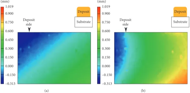
After EBAM, the out-of-plane displacement distribution in the 3 mm thick Ti6Al4V substrate with a BH of 50 mm was evaluated (Figure 8(a)), and the maximum value was roughly 0.70 mm. After postdeposition SR, the maximum displace-ment increased to 1.15 mm (Figure 8(b)), but the out-of-plane displacement distribution appeared to be more homogeneous in the bulk of the Ti6Al4V substrate. Specifically, in the SRed condition, the opposite edges on the top and bottom surfaces were seen to have relatively large displacements. Hence, to transition the developed EBAM process towards the actual repair of the fan blade, sacrificial run-on and run-off lengths may be considered to limit the displacement further. Nonetheless, in consideration of the current repair specifi-cation for the Ti6Al4V fan blade, the maximum displacement occurring in the Ti6Al4V substrate after EBAM and SR is within the tolerable limit of 2 mm for returning to service.
3.3. Residual Stresses. For the as-deposited and SRed con-ditions, the near-surface residual stresses were obtained by incremental hole-drilling measurements in the Ti6Al4V
0 200 400 600 800 1000 1200 0 1000 2000 Temperature (°C) Time (s) End of building process (a) 0 200 400 600 800 1000 1200 0 1000 2000 Temperature (°C) Time (s) End of building process (b)
Figure 5: Thermal profiles measured at (a) midthickness (thermocouple 1) and (b) midwidth (thermocouple 2) locations shown in Figure 1(a) during EBAM of a Ti6Al4V wall build (50 mm BH) on a 3 mm thick substrate.
Figure 6: Ti6Al4V wall structure built with a BH of 105 mm on a 3 mm thick Ti6Al4V substrate using a wire-fed EBAM process in a vacuum environment.
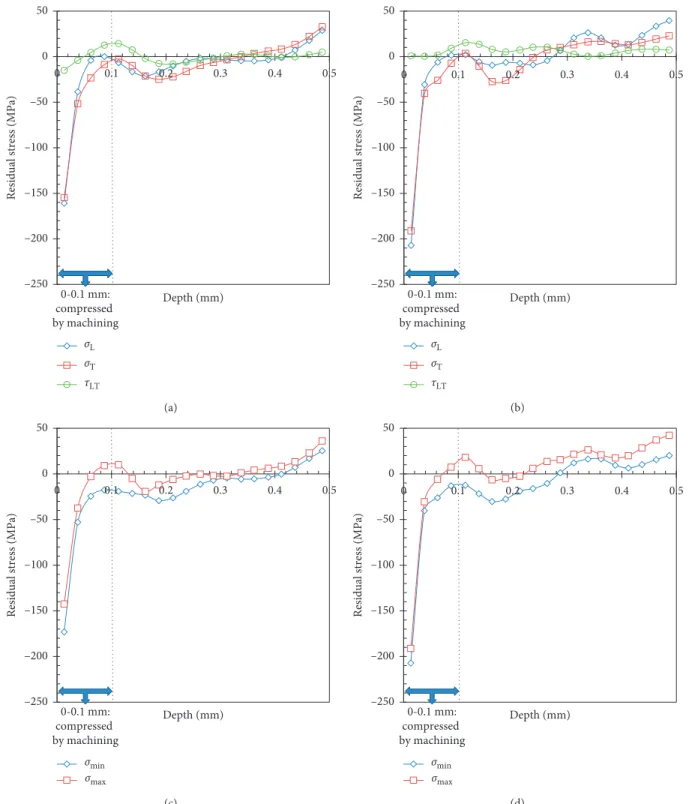
substrate at the location indicated in Figure 4. Overall, for both conditions, the magnitude of the residual stresses with increasing depth in the Ti6Al4V substrate remained small relative to the nominal YS of the Ti6Al4V alloy, as illustrated in Figure 9. An interesting trend is the oscillating nature of the residual stress profiles, which may be an outcome of the layer-by-layer EBAM process where the sum of stresses are due to the repeated heating and cooling cycles that involve (1) thermal expansion during rapid heating and melting and (2) contraction upon solidification and cooling of each deposited layer. Previously, Salmi et al. [36] also observed an oscillating trend in the residual stresses for AM of AlSi10Mg and ascribed similarities to stresses that develop during multipass welding processes [37, 38] where the weld bead experiences repeated thermal cycling.
Table 2 gives the residual stresses in the Ti6Al4V sub-strate in the as-deposited and SRed conditions. Both σLand
σTwere slightly compressive in the as-deposited condition,
while, after postdeposition SR, these were determined to be slightly tensile. The principal residual stresses, σminand σmax,
in the Ti6Al4V substrate were also relatively small, at <2% of the YS of the alloy, and statistically similar for the as-deposited and SRed conditions. These low residual stresses measured in the Ti6Al4V substrate bode favorably for mitigating the distortion and cracking during heavy repair using the EBAM technology. The low residual stresses developing during EBAM can be reasoned on the basis of the elevated temperatures experienced in the Ti6Al4V substrate. These temperatures effectively maintain a preheat on the Ti6Al4V substrate throughout the EBAM process, which
(a)
(b)
Figure 7: X-ray micro-CT scans of the Ti6Al4V wall shown in Figure 6 that was deposited to a BH of 105 mm by wire-fed EBAM and exhibited no indications: (a) X-Z plane at midthickness of deposit and (b) X-Y planes along the BH.
reduces the temperature gradients and, thereby, alleviates the thermal stresses that lead to the development of residual stresses and distortion. This finding is consistent with the experimental and finite element modelling results of Cao et al. [27] for EBAM Ti6Al4V. Denlinger et al. [39] have also attributed the low residual stresses during EBAM to be an effect of stress relaxation in Ti6Al4V. In particular, Ti6Al4V undergoes a solid-state phase transformation between its two allotropic forms, HCP α and BCC β, that, on a mi-croscopic level, is accompanied by a change in the specific volume and contributes to the development of trans-formation strains. Denlinger and Michaleris [40] simulated the effect of the solid-state phase transformation strain on the residual stresses in Ti6Al4V during wire-fed EBAM of a single thin-wall structure deposited on a 12.7 mm thick substrate; they reported that in Ti6Al4V, the transformation strain acts to oppose the strain due to contraction from solidification of the deposited material and leads to re-laxation of the residual stresses along with a reduction in the accumulated distortion. Their work indicated that the transformation strain could negate all the strains at tem-peratures above 690°C [39, 40]. Hence, the basis of the low
residual stresses and small distortions determined in the present study can be attributed to the elevated temperatures experienced in the Ti6Al4V substrate during EBAM that reduce the thermal gradients and possibly introduce stress relaxation effects.
3.4. Microstructure. The microstructure from the Ti6Al4V substrate to the first layers of the Ti6Al4V deposit is shown in Figure 10(a). In the Ti6Al4V substrate, the rolled recrystallized texture stemming from the mill-annealed thermomechanical processing route is apparent, and the bimodal microstructure consisted of fine equiaxed α grains with intergranular and interlamellar β. The Ti6Al4V deposit microstructure, shown in Figure 11, results from the
solidification of the molten Ti6Al4V wire bead into the high-temperature β phase that forms upon cooling from the liquidus temperature of ∼1660°C. For DED technologies,
such as EBAM, heat extraction is highly directional with the steepest temperature gradients arising due to more effective conduction through the substrate relative to any radiative and/or convective losses. Hence, within the first few layers of the deposit, the β phase begins to solidify as columnar grains. When the temperature of the deposited Ti6Al4V descends below ∼996°C ± 20°C, allotropic transformation of the
high-temperature β phase (BCC) occurs and the low-high-temperature α phase (HCP) begins to nucleate at the β grain boundaries through an orientation relationship, widely known as the BOR. From the BOR—{110}β || (0001)α, <1120>α ||
<11 1>β—12 possible primary α phase variants, involving
different combinations of families of planes and directions, can nucleate at the interface of a single prior-β grain. Further cooling leads to the growth of nucleated α phase as platelets inside the prior-β grains, forming so-called α colonies that develop into a complex lamellar microstructure, often re-ferred to as α + β basket-weave. This finding is comparable to reported microstructures for Ti6Al4V deposited by wire-fed EBAM [15, 23].
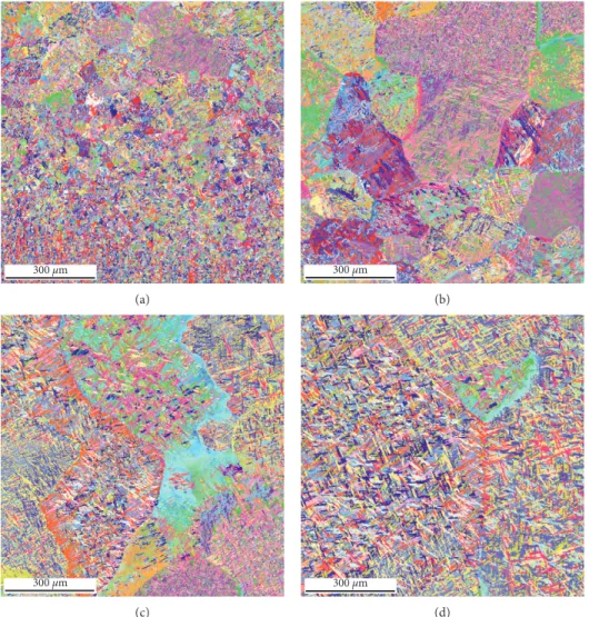
The room temperature microstructures, illustrated in Figure 11, give evidence to the prior-β grain formation characteristics during the early stages (first few layers) of Ti6Al4V deposition with the wire-fed EBAM process. From the very fine bimodal microstructure of the Ti6Al4V sub-strate, the columnar prior-β grain configuration developed in the deposit through an interface region consisting of equiaxed prior-β grains, as shown in Figure 11(a). Initially, the columnar prior-β grains were comparatively small in size in the layers neighboring the equiaxed interface region (Figures 11(b) and 11(c)) relative to that in the subsequent layers deposited (Figure 11(d)); this gradually gave rise to the columnar prior-β macrostructure visible on the surface of the deposit, as shown in Figure 6. Reconstruction of the
Deposit side Deposit Substrate (mm) 1.019 0.900 0.750 0.600 0.450 0.300 0.150 0.000 –0.150 –0.313 (a) Deposit side Deposit Substrate (mm) 1.019 0.900 0.750 0.600 0.450 0.300 0.150 0.000 –0.150 –0.313 (b)
Figure 8: Out-of-plane displacement map in the Ti6Al4V substrate due to EBAM of a Ti6Al4V wall structure with a 50 mm BH. (a) As-deposited after EBAM. (b) After EBAM and SR (700°C, 2 hours).
–250 –200 –150 –100 –50 0 50 0 0.1 0.2 0.3 0.4 0.5
Residual stress (MPa)
Depth (mm) 0-0.1 mm: compressed by machining σT σL τLT (a) –250 –200 –150 –100 –50 0 50 0 0.1 0.2 0.3 0.4 0.5
Residual stress (MPa)
Depth (mm) 0-0.1 mm: compressed by machining σT σL τLT (b) –250 –200 –150 –100 –50 0 50 0 0.1 0.2 0.3 0.4 0.5
Residual stress (MPa)
Depth (mm) 0-0.1 mm: compressed by machining σmin σmax (c) –250 –200 –150 –100 –50 0 50 0 0.1 0.2 0.3 0.4 0.5
Residual stress (MPa)
Depth (mm) 0-0.1 mm: compressed by machining σmin σmax (d)
Figure 9: Near-surface residual stress distributions in the Ti6Al4V substrate resulting from EBAM of a 50 mm BH Ti6Al4V wall structure with and without SR, as determined through incremental hole-drilling measurements. It is noteworthy that the residual stress data for depths of 0-0.1 mm have compression effects from machining. (a) As-deposited. (b) SRed. (c) As-deposited. (d) SRed.
Table 2: Residual stresses in the Ti6Al4V substrate.
As-deposited SRed
Longitudinal stress, σL(MPa) −2 5
Transverse stress, σT(MPa) −3 10
Shear stress, τLT(MPa) 0.2 7.2
Maximum principal stress, σmax(MPa) 7.9 16.2
prior-beta phase (Figure 10(b)) also clearly highlights the evolution of the beta grain morphology along the build direction. At the interface between the substrate and the deposit, fine equiaxed β grains, resulting from heteroge-neous nucleation on the substrate, are present. Progressive coarsening and transition to a columnar morphology occur as the distance from the substrate increased. Overall, the microstructure within the fine equiaxed as well as the small and coarse columnar prior-β grains consisted of α colonies having a basket-weave appearance. The main difference in this basket-weave microstructure was the α colony size and
the thickness of the individual α platelets/lamellae (Fig-ure 12). Specifically, in the neighboring region of the Ti6Al4V substrate, the equiaxed prior-β grains were small in size, which limited the maximum size of the α colonies because the growth of the α lamellae was restricted by impinging colonies growing from other locations along the grain boundary. By contrast, as the prior-β grains coarsen, the size of the α colonies increases, as exemplified by comparing Figures 11(b) and 11(d); this, in turn, results in an increase in the α lamellae thickness, as revealed in Fig-ure 13 and tabulated in Table 3.
PM Interface Deposit layers 2–5
100 μm 100 μm Titanium (α) Titanium (β) 1010 2110 0001 111 101 001 (a) (b)
Figure 10: EBSD map of (a) the α phase and (b) numerical reconstruction of the parent β phase in the Ti6Al4V wall structure built on a Ti6Al4V substrate using wire-fed EBAM.
300 μm (a) 300 μm (b) 300 μm (c) 300 μm (d)
Figure 11: Higher-resolution EBSD maps of the Ti6Al4V wall deposit: (a) just adjacent to the interface with the substrate, (b) coarser equiaxed grains in the third layer, (c) initial columnar grains starting from the fourth layer, and (d) large columnar prior-β grains beyond the fifth layer.
Titanium (α) 1010
2110 0001
300 μm 10 μm
Figure 12: High-resolution EBSD map of the Ti6Al4V wall showing the details of colony α microstructure in deposit layer 4.
(a) (b)
Figure 13: Backscattered electron micrographs showing the typical alpha plate characteristics in (a) small columnar grains and (b) coarse columnar grains.
Qualitative distributions of the main alloying elements in Ti6Al4V were investigated within the developed micro-structure of the deposit using EDS mapping as illustrated in Figure 14. Aluminum was found to be concentrated within the α platelets and almost depleted from the α platelet boundaries. On the other hand, vanadium and iron were mostly concentrated along the α platelets boundaries. These observations are in line with reported results [41, 42], as aluminum is a well-known α stabilizer while iron and va-nadium are β stabilizers. Hence, the main phase present along the α grain boundaries can be assuredly reasoned as the BCC stabilized β phase. It is noteworthy that when using the SEM in the PDBSE mode, the β phase is generally associated with the lighter gray/white areas relative to the darker gray regions that are associated with the α phase, as demarcated in Figure 14(a). Using the ImageJ image processing software, the β phase distribution within the developed microstructure of the deposit was quantitatively estimated, as shown in Figure 14(b), using an intensity threshold to isolate the β phase (in red). The average β phase fraction was determined to be 9.6% ± 0.9%, which is typical for a composition described by the 600°C isotherm of the
Ti6Al4V ternary phase diagram [43]. This finding is in agreement with the slower cooling rates experienced in EBAM applications that enable diffusion-controlled type of microstructures [44].
3.5. Microhardness. The average hardness measured in the X-Y, X-Z, and Y-Z planes of the Ti6Al4V wall build and the PM substrate were statistically similar, as illustrated in Figure 15; these values were then used to determine the bulk material hardness, as given in Table 4, by av-eraging the values measured in the different planes. In particular, the bulk hardness of the as-deposited Ti6Al4V wall build, 319 ± 14 HV, was statistically similar to the as-received PM (322 ± 13 HV). After SR, the bulk hardness of the Ti6Al4V deposit, 304 ± 14, was also statistically similar (∼3% difference) to the SRed PM hardness of 314 ± 14.
3.6. Tensile Testing. The static tensile behavior and prop-erties measured for the EBAM Ti6Al4V in the SRed con-dition are compared in Figure 16 and Table 5 with the SRed PM. Overall, the dependence of tensile deformation be-havior on the specimen orientation was limited and arguably statistically similar in consideration of the standard de-viations of these properties. For instance, detailed analysis of the tensile properties demonstrates the minor effect of an-isotropy in the SRed Ti6Al4V substrate, as the YS, UTS, and %El are nearly identical along the RD (PMZ) and
perpen-dicular to the RD (PMX); the former was roughly 5% higher
in strength and 8% lower in fracture strain relative to the latter. Similarly, the EBAM Ti6Al4V in the SRed condition exhibited even smaller differences in the tensile properties along the DD (DX) and perpendicular to the DD (DZ); the
difference between the former and latter was less than 2% in strength and 5% in fracture strain. In either case, the tensile properties of the EBAM Ti6Al4V deposit (DXand DZ) met
the minimum requirements of ASTM F2924-14 and ASTM F1108-14 for PBF and cast Ti6Al4V, respectively. This finding is reasonable in consideration of the general processing history for EBAM, PBF, and cast Ti6Al4V that involves solidification of molten Ti6Al4V into the high-temperature β phase and the development of a lamellar α + β basket-weave microstructure within the columnar prior-β grains at room temperature. Interestingly, the tensile properties of the EBAM Ti6Al4V deposit also nearly met the minimum requirements stipulated in AMS 4911P for wrought Ti6Al4V that typically consists of bimodal microstructures (fine equiaxed α grains with intergranular and interlamellar β) due to deformation processing. It is noteworthy that the tensile properties reported for wire-fed laser deposited Ti6Al4V in the SRed condition (600°C, 4 hours) with orientations of D
Xand DZ
included average UTS values of ∼975 MPa and ∼945 MPa, respectively, and average fracture strains of ∼4% and ∼8%, respectively [35]. For laser-deposited Ti6Al4V, the low fracture strains are a common problem [48] that may possibly be related to the martensitic microstructure and/ or gas shielding protection of the build. Also, previous research works on EBAM of Ti6Al4V have reported different values for the strength and ductility in the as-deposited condition; values for the UTS and total elon-gation have ranged from just under 800 MPa [20] to 925 MPa [18] and the total elongation from 9% [20] to 13% [18]. The tensile properties of the SRed EBAM Ti6Al4V in the present work are in relatively good agreement with the higher values reported in [18].
The tensile properties of D-PMZ in the SRed condition
consisted of a YS of 856.8 ± 14.1 MPa, UTS of 923.9 ± 11.1 MPa, and fracture strain of 12.8 ± 0.7%, with failure occurring ex-clusively in the EBAM Ti6Al4V deposit. These tensile properties and the deformation behavior of SRed D-PMZwere found to be
statistically similar to SRed DZ and met the minimum
re-quirements of ASTM F2924-14 and ASTM F1108-14 for PBF and cast Ti6Al4V. Also, from a repair perspective, the occur-rence of failure in the deposited region is ideal for maintaining the integrity of the underlying Ti6Al4V substrate during service and periodic maintenance, repair, and overhaul.
In general, the good elongation developed in DX, DZ, and
D-PMZ can also be associated to the observations drawn
from the EDS maps in Figure 14. Indeed, a fully developed β phase along the α grain boundaries increases the cross slip probability of the moving dislocations during static tensile testing. This is again induced by the BOR and the lower stacking-fault energy associated with Ti6Al4V [34, 41, 49] and shows that dislocations can be transmitted from the α phase basal (0002)α[11-20]αor prismatic (10-10)α[11-20]α
slip systems onto the β phase (110)β[1-11]βor (112)β[1-21]β
slip systems.
Table 3: Average thickness of α platelets.
Region Average α platethickness (μm) Standarddeviation
Small columnar grains 0.90 0.25
After static tensile loading of the different specimens, the fracture surfaces were examined at low and high magnifi-cations using SEM. Figure 17 reveals the typical ductile fracture characteristics observed from the failed tensile specimens DX, DZ/D-PMZ, PMX, and PMZ. In particular, the
fracture surface of the Ti6Al4V deposited by EBAM was rough in appearance and exhibited ductile rupture with a
large number of microscopic tear ridges, similar to that observed for the PM. The principal failure mechanism of the both the Ti6Al4V deposited by EBAM and the PM involved microvoid formation, growth, and coalescence of voids. From a microscale perspective, though it is difficult to di-rectly relate the dimple size with ductility, the presence of a healthy population of fine, uniformly distributed dimples on
10 μm β α (a) β 10 μm (b) Ti 10 µm (c) Al 10 µm Al (d) Fe 10 µm (e) V 10 µm (f)
Figure14: High-resolution ESD map showing the distribution of alloying elements in the Ti6Al4V deposit microstructure and the β phase fraction. 290 295 300 305 310 315 320 325 330 Hardness, HV (500 g load) X-Y X-Z Y-Z PM Deposit PM Deposit 322 316 314 320 319 310 304 302 324 322 317 307 Stress relieved As-received/as-deposited
the tensile fracture surfaces are typically indicative of high microstructural integrity and the occurrence of plastic deformation. In particular, for titanium alloys, a dimpled rupture can occur under static loading conditions, such as in a tensile test; such a high energy absorbing fracture mode is, of course, a highly desirable fracture mechanism and has been attributed to the high degree of plasticity in the material [50].
3.7. Fatigue Testing. It is well known that fan blades used in the first-stage compressor of aeroengines are affected by both LCF and HCF. In LCF, the material is subjected to high stresses that cause primarily plastic strains and fracture at a relatively low number of cycles; by contrast, in HCF, the
0 200 400 600 800 1000 1200 0 5 10 15 Stress (MPa) Strain PMz PMx Dx D-PMz Dz
Figure 16: Typical static tensile behavior of the Ti6Al4V wall structure relative to the wrought Ti6Al4V substrate, both in the SRed condition.
Table 5: Average mechanical properties of EBAM and PM Ti6Al4V.
Specimen type YS (MPa) UTS (MPa) % El
DZ 849.3 ± 13.4 914.5 ± 10.6 12.7 ± 0.7 DX 860.2 ± 14.2 934.0 ± 12.2 13.4 ± 0.8 D-PMZ 856.8 ± 14.1 923.9 ± 11.1 12.8 ± 0.7 PMZ 1058.2 ± 12.3 1115.4 ± 9.6 13.7 ± 0.5 PMX 988.6 ± 11.9 1059.2 ± 10.5 14.8 ± 0.6 ASTM F1108-14 758 860 8 Cast Ti6Al4V [45] ASTM F2924-14 825 895 10 PBF Ti6Al4V [46] AMS 4911P [47] 869 920 10 Wrought Ti6Al4V (1.60–4.76 mm thick)
Table 4: Average Vickers microhardness, 500 g load.
Specimen condition Plane Vickers hardness, HV Bulk material hardness, HV
PM (as-received) X-Y 322 ± 15 322 ± 13 X-Z 320 ± 11 Y-Z 324 ± 14 PM (SRed) X-Y 314 ± 12 314 ± 14 X-Z 310 ± 14 Y-Z 317 ± 15 As-deposited X-Y 316 ± 9 319 ± 11 X-Z 319 ± 12 Y-Z 322 ± 11 SRed X-Y 307 ± 13 304 ± 14 X-Z 304 ± 16 Y-Z 302 ± 13
material is subjected to low stresses and mainly elastic strains that lead to fracture at a relatively large number of cycles. Thus, to evaluate the LCF and HCF behavior of the Ti6Al4V wall deposit in the SRed condition (PM-DZ) relative to
wrought Ti6Al4V substrate (PMZ) in the SRed condition,
cyclic loading at different stress amplitudes was undertaken at room temperature using a frequency of 6 Hz. The typical fatigue life curves (also referred to as W¨ohler or S-N curve),
plotted using the experimental data of maximum stress as a function of number of cycles to failure for PM-DZand PMZ,
are given in Figure 18(a) and compared with the reported literature on cast, cast plus HIP, and wrought-processed Ti6Al4V [51]. From Figure 18(a), the overall fatigue behavior of the SRed PM-DZwas similar to the wrought SRed PMZ.
Specifically, the fatigue properties characterized by the S-N curve obtained under tension-compression cyclic loading of
(a) (b)
(c) (d)
(e) (f )
(g) (h)
Figure 17: Representative SEM fractographs for the tensile samples of (a, b) PMX, (c, d) PMZ, (e, f ) DX, and (g, h) DZ/D-PMZ(with failure in
the PM-DZand PMZexhibited a continuous decrease of the
stress amplitude with increasing number of cycles in the region from ∼103 to 107 cycles at the load ratio studied
(R 0.1). Also, as illustrated in Figure 18(b), in a double-log scale of the maximum stress versus the number of reversals to failure, the fatigue behavior/slope was similar for SRed PM-DZ and SRed PMZ, with the fatigue strength of the
former being just slightly lower than the later. In comparison to reported literature [52], the fatigue properties of SRed PM-DZare comparable to wrought annealed Ti6Al4V and/
or cast plus HIP properties.
The LCF behavior of SRed PM-DZis characterized by
relatively high maximum stress values that lend good as-surance of the integrity of the Ti6Al4V deposit fabricated by wire-fed EBAM. For example, the endurance at 925 MPa was just over 8.2 k cycles, and the endurance for maximum stress values between 825 MPa and 900 MPa ranged from ap-proximately 13 k and 18 k cycles. Under similar maximum stress values, the endurance of PMZranged from
approxi-mately 30 k to 90 k cycles. In the HCF region, endurance limit values of 660 MPa and 690 MPa at 107 cycles were
extrapolated for SRed PM-DZand SRed PMZ, respectively,
through regression analysis of the experimental data plotted in Figure 18(b).
Analysis of the fatigue fracture surface was undertaken for the SRed PM-DZand SRed PMZsamples, and for the
different combinations of LCF and HCF conditions, failure always occurred by surface initiation. Also, for SRed PM-DZ, failure occurred exclusively in the deposit.
At the various maximum stress levels spanning from LCF to HCF, the macroscopic and microscopic characteristics of the fatigue fracture surface were observed to be rela-tively similar for SRed PMZ and SRed PM-DZ;
repre-sentative images at low and high magnifications are given in Figures 19–22 to illustrate the crack initiation and
propagation characteristics. For instance, in the region of damage initiation, the possible site of microscopic crack initiation, as demarcated with an arrow in Figures 19(a), 20(a), 21(a), and 22(a), was reasoned to have occurred from a surface asperity. For both the SRed PMZand SRed
PM-DZ, the crack initiation site exhibited planar
quasi-cleavage facets without any visible indication of pores or inclusions. This finding is consistent with previous re-ported work that has indicated that in the absence of microstructural inhomogeneities, such as pores and in-clusions, both the bimodal and fully lamellar micro-structures of wrought Ti6Al4V exhibit cleavage facets at the fatigue crack surface initiation sites [51–55].
After initiation, continued cyclic deformation of SRed PMZ and SRed PM-DZ resulted in microplastic strain
(damage) accumulation, and the early crack growth region consisted of a flat and nearly featureless transgranular surface, in which quasicleavage facets were visible at high magnifications, as revealed in Figures 19(b), 19(c), 20(b), 20(c), 21(b), 21(c) and 22(b), and 22(c). High-resolution imaging of the transgranular surface within the stable crack growth area revealed the presence of serial and very fine plastic fatigue striations on the surface of the cleavage facets, as illustrated in Figures 19(d), 20(d), 21(d), and 22(d). In the final stages of stable crack growth, the onset of fatigue overloading of SRed PMZand SRed PM-DZled to
fast fracture; within the final failure region, a dimpled fracture surface, consisting of fine microscopic voids, was observed as revealed in Figures 19(e), 20(e), 21(e), and 22(e). Though the general fracture characteristics of SRed PMZand SRed PM-DZwere observed to be similar under
LCF and HCF conditions, subtle differences could be noted. For instance, at low stress amplitudes (HCF), the striations observed were finer with a narrower spacing (as indicated in the inset images shown in Figures 21(d) and
PM-Dz PMz Wrought anneal Cast + HIP Cast 0 200 400 600 800 1000 1200
1.E + 03 1.E + 04 1.E + 05 1.E + 06 1.E + 07
Maximum stress (MPa)
Number of cycles to failure (Nf)
(a) PM-Dz PMz y = –0.0445x + 3.1651 R2 = 0.7596 y = –0.0385x + 3.1026 R2= 0.7691 2.5 2.6 2.7 2.8 2.9 3 3.1 3.2 3.3 3.4 3.5 3.5 4.0 4.5 5.0 5.5 6.0 6.5 7.0 7.5 Log Δ σ (maximum stress) Log 2Nf (b)
Figure18: Fatigue life curves for the SRed Ti6Al4V wall deposit and SRed wrought Ti6Al4V tested at room temperature, R 0.1 and 6 Hz. The superimposed fatigue performance of unnotched Ti6Al4V (tested at R 0.1) for wrought, cast plus HIP, and cast products were reproduced from [50].
22(d)) and the microcracks appeared less prominent rel-ative to these respective features on the LCF fracture surfaces.
In the present work, the qualitative and quantitative assessments of the Ti6Al4V structures built using wire-fed EBAM indicated high tensile strength and ductility, good LCF and HCF properties, and a low level of residual stresses and distortion. These results highlight the good intrinsic mechanical resistance of the deposited material. From a refurbishing perspective for overhauling heavily damaged fan blades, the present encouraging results indicate the high
potential for advanced repair with the EBAM process. Relative to the conventional repair scheme for refurbishing extensively eroded titanium alloy fan blades, eliminating the preparations for fabricating a repair patch, using stamping, rolling or forging, would render significant savings in high-value material waste, production lead time, and manufacturing costs. Hence, future work is aimed at re-search on understanding the vibration fatigue behavior of wire-fed EBAM Ti6Al4V to complement the uniaxial fatigue data reported in the present work and advance a damage tolerance design using a test configuration that introduces
(a)
(b) (c)
(d) (e)
Figure 19: LCF fracture surface of PMZ(failure at ∼5 × 10³cycles): (a) overall fracture surface (arrow designates surface region where failure
initiated), (b) the region of crack initiation and outward progression of fatigue damage, (c) the flat and nearly featureless transgranular surface in the region of early crack growth, (d) high-magnification imaging of the region of stable crack growth showing a distribution of fine microscopic cracks, as well as areas of fine and shallow striations, and (e) fine microscopic voids in the region of unstable crack growth (overload).
the complex operational and loading conditions of turbine engine blades.
4. Conclusions
Based on the results of the present research on developing a repair process to simulate refurbishment of a Ti6Al4V fan blade using electron beam additive manufacturing (EBAM) with wire feeding, the following conclusions can be drawn: (i) A single-bead multilayer process using the EBAM technology with wire feeding was developed and demonstrated for building a Ti6Al4V wall structure, up to 105 mm in height on a 3 mm thick Ti6Al4V
substrate. The microstructure of the deposit exhibited typical solidification features of columnar prior-beta grains and acicular alpha that was either lamellar within the interior of the deposit or as randomly oriented plates in the vicinity of the de-posit surface.
(ii) Nondestructive inspection using 3D X-ray micro-computed tomography technology was capable of detecting discontinuities directly in the additive manufactured layers without the need for surface machining. Through the inspection the Ti6Al4V wall structure, it was confirmed that the deposit with a build height of 105 mm on the 3 mm thick
(a)
(b) (c)
(d) (e)
Figure 20: LCF fracture surface of PM-DZ(failure at ∼8 × 10³cycles): (a) overall fracture surface (arrow designates surface region where
failure initiated), (b) the region of crack initiation and outward progression of fatigue damage, (c) the flat and nearly featureless transgranular surface in the region of early crack growth, (d) high-magnification imaging of the region of stable crack growth showing a distribution of fine microscopic cracks, as well as areas of fine and shallow striations, and (e) fine microscopic voids in the region of unstable crack growth (overload).
substrate (built using optimized parameters) was fully dense and defect-free.
(iii) The maximum out-of-plane displacement in the 3 mm thick Ti6Al4V substrate after EBAM was about 0.70 mm. After stress relieving (SR), the maximum displacement increased to 1.15 mm, but the distribution in the central region of the Ti6Al4V substrate was more homogeneous relative to that in the as-deposited condition. However, these maxi-mum displacement values in the Ti6Al4V substrate
after EBAM and SR were within the tolerable limit for the repair requirements of the fan blade. (iv) The bulk microhardness in the deposit was 319 HV
and 304 HV in the as-deposited and stress relieved conditions, respectively, which was statistically comparable to the parent material hardness of 322 HV and 314 HV in the as-received and stress re-lieved conditions, respectively.
(v) The static tensile properties of the Ti6Al4V EBAM met adequately the minimum requirements of the
(a)
(b) (c)
(d) (e)
Figure 21: HCF fracture surface of PMZ(failure at ∼3 × 10⁶cycles): (a) overall fracture surface (arrow designates surface region where failure
initiated), (b) the region of crack initiation and outward progression of fatigue damage, (c) the flat and nearly featureless transgranular surface in the region of early crack growth (d) high-magnification imaging of the region of stable crack growth showing a distribution of fine microscopic cracks, as well as areas of fine and shallow striations, and (e) fine microscopic voids in the region of unstable crack growth (overload).
ASTM F2924-14 and ASTM F1108-14 for PBF and cast Ti6Al4V, respectively. Tensile fracture occurred exclusively in the deposit through a ductile rupture fracture mechanism, which explains the relatively high plasticity of the Ti6Al4V build (i.e., a total elongation of 13–15%).
(vi) The fatigue properties obtained under tension-compression cyclic loading indicated that the S-N behavior of the 50% deposit-50% parent material samples was comparable to the wrought parent material. Fatigue fracture in the deposit and wrought parent material progressed similarly:
surface initiation of failure, microplastic strain accumulation with transgranular progression of fatigue damage, and final overload failure with dimpled features of fine microscopic voids.
Acronyms
AM: Additive manufacturing BCC: Body-centered cubic BH: Build height
BOR: Burgers orientation relationship CT: Computed tomography
(a)
(b) (c)
(d) (e)
Figure 22: HCF fracture surface of PM-DZ(failure at ∼3 × 10⁶cycles): (a) overall fracture surface (arrow designates surface region where
failure initiated), (b) the region of crack initiation and outward progression of fatigue damage, (c) the flat and nearly featureless transgranular surface in the region of early crack growth, (d) high-magnification imaging of the region of stable crack growth showing a distribution of fine microscopic cracks as well as areas of fine and shallow striations, and (e) fine microscopic voids in the region of unstable crack growth (overload).
DD: Deposition direction DED: Direct energy deposition E: Elastic modulus
EB: Electron beam
EBAM: Electron beam additive manufacturing EB3F: Electron beam freeform fabrication EBSD: Electron backscatter diffraction EDS: Energy dispersive X-ray spectroscopy % El: Total percent elongation
FEG: Field emission gun HCP: Hexagonal close packed HIP: Hot isostatic pressing NDE: Nondestructive evaluation PBF: Powder bed fusion
PDBSE: Photo diode backscattered electron PM: Parent material
Pmax: Maximum load
Pmin: Minimum load
RD: Rolling direction SR: Stress relief
SEM: Scanning electron microscopy UTS: Ultimate tensile strength YS: Yield strength
ε1, ε2, ε3: Strain gage numbers 1, 2, and 3
α: Alpha
β: Beta
ω: Angle between strain gage one (ε1) to the
maximum principal stress
σL: Residual longitudinal stress (parallel to RD of
substrate and BH)
σT: Residual transverse stress (perpendicular to RD
of substrate and parallel to DD) σmax: Maximum principal stress
σmin: Minimum principal stress
τLT: Residual shear (L-T) stress.
Data Availability
The data used to support the findings of the study are in-cluded within the article.
Conflicts of Interest
The authors declare that they have no conflicts of interest.
Acknowledgments
This work was supported by the Defence Technologies and Sustainment Program of the National Research Council of Canada (NRC) and the Annual Research Program of IHI Corporation. The authors are grateful to X. Pelletier (NRC) for supporting the EBAM trials and metallography of the samples, A. Beauchesne for supporting the X-ray microCT measurements, and M. Guerin (NRC) for sup-porting the Argus
®
measurements, tensile testing, and fatigue testing. The authors are also grateful to N. Bro-dusch and F. Sikan (McGill University) for acquisition for the high-resolution EDS maps and measurement of the alpha plate thickness.References
[1] P. C. Patnaik, M. R. Pishva, J. E. Elder, W. Doswell, and R. Thamburaj, “Repair and life extension of titanium alloy fan blades in aircraft gas turbines,” in Proceedings of Gas Turbine
and Aeroengine Congress and Exposition (89-GT-166), June
1989.
[2] P. Azar, P. Li, P. C. Patnaik, R. Thamburaj, and J.-P. Immarigeon, “Electron beam weld repair and qualifi-cation of titanium fan blades for military gas turbine engines,” in Proceedings of NATO-RTO-MP-69 Specialists’ Meeting on
Cost Effective Application of Titanium Alloys in Military Platforms, 18–1-18–6, Loen, Norway, May 2001.
[3] P. A. Kobryn, N. R. Ontko, L. P. Perkins, and J. S. Tiley, “Additive manufacturing of aerospace alloys for aircraft structures,” in Proceedings of NATO-RTO-AVT-139
Special-ists’ Meeting on Cost Effective Manufacture Via Net-Shape Processing, 3–1-3–14, Neuilly-sur-Seine, France, May 2006.
[4] B. Dutta and F. H. Froes, “The additive manufacturing (AM) of titanium alloys,” in Titanium Powder Metallurgy Science,
Technology and Applications, M. Qian and F. H. Froes, Eds.,
pp. 447–468, Butterworth-Heinemann, Waltham, MA, USA, 2015.
[5] E. Herderick, “Additive manufacturing of metals: a review,” in
Proceedings of Materials Science and Technology (MS&T),
pp. 1413–1425, Columbus, OH, USA, 2011.
[6] K. V. Wong and A. Hernandez, “A review of additive manufacturing,” ISRN Mechanical Engineering, vol. 2012, Article ID 208760, 10 pages, 2012.
[7] L. Portol´es, O. Jord´a, L. Jord´a, A. Uriondo, M. Esperon-Miguez, and S. Perinpanayagam, “A qualification procedure to manufacture and repair aerospace parts with electron beam melting,” Journal of Manufacturing Systems, vol. 41, pp. 65– 75, 2016.
[8] J.-P. Immarigeon, A. K. Koul, W Beres et al., “The aging of engines: an operator’s perspective,” in Proceedings of
NATO-RTO-AVT Lecture Series on Aging Engines, Avionics, Sub-systems and Helicopters, 2–1-2–20, Atlantic City, NJ, USA,
October 2000.
[9] J.-P. Immarigeon, W. Beres, P Au et al., “Life cycle man-agement strategies for aging engines,” in Proceedings of
NATO-RTO-AVT Specialists’ Meeting on Life management techniques for ageing air vehicles, 17–1-17–16, Manchester,
UK, 2001.
[10] N. K. Dey, F. W. Liou, and C. Nedic, “Additive manufacturing laser deposition of Ti-6Al-4V for aerospace repair applica-tions,” in Proceedings of Solid Freeform Fabrication, pp. 853–858, Austin, TX, USA, 2013.
[11] I. Gibson, D. Rosen, and B. Stucker, “Directed energy de-position processes,” in Additive Manufacturing Technologies, pp. 245–268, Springer Science + Business Media, New York, NY, USA, 2015.
[12] A. Uriondo, M. Esperon-Miguez, and S. Perinpanayagam, “The present and future of additive manufacturing in the aerospace sector: a review of important aspects,” Proceedings
of the Institution of Mechanical Engineers, Part G: Journal of Aerospace Engineering, vol. 229, no. 11, pp. 2132–2147, 2015.
[13] K. M. B. Taminger, R. A. Hafley, and D. L. Dicus, “Solid freeform fabrication: an enabling technology for future space missions,” in Proceedings of International Conference on Metal
Powder Deposition for Rapid Manufacturing, pp. 51–60, San
Antonio, TX, USA, 2002.
[14] K. M. B. Taminger and R. A. Hafley, “Characterization of 2219 aluminum produced by electron beam freeform fabrication,”


![Figure 4: Schematic diagram showing the hole-drilling location in the Ti6Al4V substrate and the strain gage rosette arrangement for measuring the strains (ε 1 , ε 2 , and ε 3 ) to determine the residual stresses according to [29].](https://thumb-eu.123doks.com/thumbv2/123doknet/14017247.457041/6.900.194.706.104.442/schematic-drilling-location-substrate-arrangement-measuring-determine-according.webp)