HAL Id: hal-00012840
https://hal.archives-ouvertes.fr/hal-00012840
Preprint submitted on 28 Oct 2005
HAL is a multi-disciplinary open access
archive for the deposit and dissemination of
sci-entific research documents, whether they are
pub-lished or not. The documents may come from
teaching and research institutions in France or
abroad, or from public or private research centers.
L’archive ouverte pluridisciplinaire HAL, est
destinée au dépôt et à la diffusion de documents
scientifiques de niveau recherche, publiés ou non,
émanant des établissements d’enseignement et de
recherche français ou étrangers, des laboratoires
publics ou privés.
Transportable laser system for atom interferometry
P. Cheinet, F. Pereira dos Santos, T. Petelski, J. Le Gouët, K. T. Therkildsen,
A. Clairon, A. Landragin
To cite this version:
P. Cheinet, F. Pereira dos Santos, T. Petelski, J. Le Gouët, K. T. Therkildsen, et al.. Transportable
laser system for atom interferometry. 2005. �hal-00012840�
ccsd-00012840, version 1 - 28 Oct 2005
Transportable laser system for atom interferometry
P. Cheinet, F. Pereira Dos Santos, T. Petelski, J. Le Gou¨et, K. T. Therkildsen, A. Clairon and A. Landragin
LNE-SYRTE, CNRS UMR8630, Observatoire de Paris, 61 avenue de l’observatoire, 75014 Paris, France
Compiled October 28, 2005
We describe an optical bench in which we lock the relative frequencies or phases of a set of three lasers in order to use them in a cold atoms interferometry experiment. As a new feature, the same two lasers serve alternately to cool atoms and to realize the atomic interferometer. This requires a fast change of the optical frequencies over a few GHz. The number of required independent laser sources is then only 3, which enables the construction of the whole laser system on a single transportable optical bench. Recent results obtained with this optical setup are also presented. 2005 Optical Society of Americac
OCIS codes: 140.3320, 120.3180, 140.3550, 120.3930.
Within the last decades, atom interferometers have de-veloped into a highly competitive tool for precision measurements.1 Atomic fountains used as atomic clocks
are the best realization of the time unit.2 Atom
inter-ferometry also promises sensors to be highly sensitive to inertial forces.3–6 The use of stimulated Raman
transi-tions to manipulate the atomic wave packet has proven to be an efficient way to obtain high accuracy devices.5, 6
In this letter, we describe a robust, compact and ver-satile laser system for atom interferometers using al-kali atoms. Such experiments basically need two differ-ent optical frequencies, whose difference remains close to the hyperfine transition frequency. When they are tuned close to the D2 transitions, they are used to cool and repump the atoms in a magneto-optical trap (MOT). When far detuned, and phase locked, they are used to induce stimulated Raman transitions for the interferom-eter.7 Since lasers are not used simultaneously for
trap-ping and Raman transitions, we have implemented a technique to use the same two lasers for both functions on our gravimeter.8It allowed us to build the whole laser
setup on a 60 × 90 cm2 optical bench.
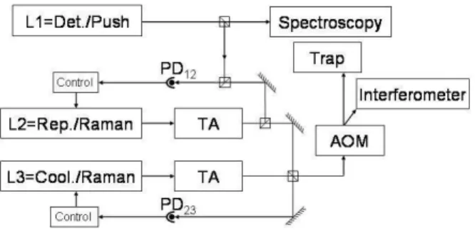
Our laser setup is shown in figure 1. A first laser L1 is locked on an atomic transition, using FM-spectroscopy9
on a saturated absorption signal. This laser constitutes an optical frequency reference and is used in our exper-iment to detect or push the atoms. A second laser L2 is alternately used as repumper or as master Raman laser. Part of the outputs of L1 and L2 are superimposed on a fast photodetector (PD12) (Hamamatsu G4176) and
the frequency of the beat note is servo locked by using a frequency to voltage converter. A third laser L3 is used alternately as cooling or as slave Raman laser. The fre-quency difference between L2 and L3 is measured with a second optical beat note on PD23. Finally, both L2
and L3 beams are superimposed and directed through an acousto-optical modulator either to a magneto-optical trap or to an atomic interferometer.
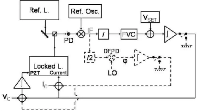
Both frequency locks of L2 and L3 use the same scheme which is shown in figure 2. The optical beat note issued from the photodetector is mixed with a reference
Fig. 1. Laser setup. The detection laser is locked on a spectroscopy signal. The repumper (resp. cooling) laser frequency is compared to the detection (resp. repumper) laser frequency with an optical beat note and servo locked. Two tapered amplifiers (TA) are used on the re-pumper and cooling lasers before they are combined on a polarizing beam splitter cube and sent alternately to the trap or to the interferometer using an acousto-optical modulator (AOM).
oscillator, down to an intermediate frequency (IF). For the L2 lock this reference is a tunable oscillator (YIG). Whereas for L3 we use a fixed 7 GHz frequency ob-tained by the multiplication of a low phase noise 100 MHz quartz oscillator. The IF signal is then sent into a digital frequency divider in order to fit into the work-ing frequency range (0-1 MHz) of a frequency to voltage converter (FVC) (AD650). A computer controlled offset voltage VSetis subtracted from the output voltage of the
FVC. The obtained error signal is integrated once and added to the laser diode current. This correction signal is integrated again and added to the piezoelectric (PZT) voltage which controls the cavity length. To change the laser frequency, one can change VSet for fine tuning or
the YIG frequency for larger frequency changes. In ad-dition, a computer controlled correction current IC and
a correction voltage VC, are added to the current and
PZT drivers to help the lock while changing the laser frequency.
For the phase lock of L3 a second path is
Fig. 2. Locking electronics. (Solid line) Frequency lock scheme. The optical beat note is mixed with a reference oscillator to an intermediate frequency (IF). The IF is converted to a voltage signal and another voltage VSet
is subtracted to obtain the error signal of the lock. It is integrated and then sent to the current driver. It is integrated once more and sent to the PZT driver. Prede-termined corrections IC and VC are added to the diode
current and to the PZT voltage during the sweep. (Dot-ted line) Phase lock scheme added to L3. The IF is com-pared to a Local Oscillator (LO) in a digital phase and frequency detector (DPFD) delivering the phase error signal. Two switches select which loop is closed.
mented. The IF frequency is divided by 2 and compared, in a digital phase and frequency detector (DPFD)10
(MCH12140), to the signal of a local oscillator at 82.6 MHz which is generated by a Direct Digital Synthesiser (DDS) (AD9852) clocked at 300 MHz. The DPFD delivers an error signal which is added through a high bandwidth servo system (∼ 4 MHz) to the laser current. It is also added to the PZT error signal before its last integration. Moreover some switches can be activated so that either the frequency lock loop or the phase lock loop is closed.
Our interferometer is an atomic gravimeter which measures the acceleration of freely falling 87Rb atoms.
Its sensitivity is given by: ∆Φ = kef fgT2, where ∆Φ
is the interferometric phase, kef f is the effective wave
vector of the Raman transition, g is the Earth’s gravity and T is the time between the interferometer’s Raman pulses.
This frequency locking system is versatile and enables to control dynamically the frequency of the two lasers, over the whole experimental sequence. It is first possible to frequency lock the lasers to the frequencies required to cool87Rb atoms in a MOT. Dividing the total available
laser power between a 2D-MOT11and a 3D-MOT,
load-ing rates of 3 × 10⁹ atoms.s−1 are obtained. Then we
turn the magnetic field off and further cool the atoms with σ+− σ− molasses down to a temperature of 2.5
µK.
Once the atoms have been released from the molasses, a frequency ramp is applied on the YIG oscillator. This
ramp induces a detuning ∆ of up to 2 GHz on both L2 and L3 to get the Raman laser frequencies. We also add a ramp on the PZT voltages VCto induce a 2 GHz sweep so
that the laser frequencies stay inside the locking range. Since the PZT mode-hop free tuning range is close to ± 0.6 GHz, it is necessary to change the current setting point of the laser during the sweep. Thus we apply ramps on the currents IC so that the laser frequencies remain
in the middle of the free tuning range. When the servo loop is closed, the lasers stay locked during the whole sequence.
In figure 3 is shown the response of the servo system to a frequency ramp of 2 GHz in 2 ms, in open and closed loop configurations. The black curve corresponds to the error signal of L2 in open loop operation. The laser fre-quency remains within 100 MHz from the locking point during the whole 2 GHz ramp. The voltage ramp does not compensate exactly the sweep because of thermal ef-fects due to the change in the laser current. When the servo loop is closed, the remaining frequency deviation is compensated for. The gray curve shows the residual fre-quency error of L2 during the sweep, and reveals residual damped oscillations of the PZT.
Fig. 3. L2 frequency error during a 2 GHz sweep imposed in 2 ms. (Black) Servo loop opened (laser unlocked). (Gray) servo loop closed (laser locked).
We then switch L3 to the phase-locked loop (PLL) after the end of the frequency ramp. We aim at obtaining an accuracy of 10−9gwhich implies that the phase error
has to remain below 0.3 mrad.8 It takes a few hundreds
of µs for the lock to come perfectly to the right frequency and to start phase locking. We display the residual phase error as a function of the delay after enabling the PLL in figure 4. 0.5 ms after the loop is closed, the phase reaches a steady state with a 2 ms time constant exponential decay. The 0.3 mrad criterion is then reached in about 2 ms. We have measured its spectral phase noise density in steady state8and calculated a total contribution of 0.56
mrad rms of phase noise in the atomic interferometer corresponding to 10−9 grms.
We want to emphasize that the Raman detuning ∆ can be changed at will and other sweeps can be added in
Fig. 4. L3 phase error. The PLL is closed at t = 0 af-ter the 2 GHz sweep. Afaf-ter 0.5 ms, the phase error is exponentially decreasing with a time constant of 2 ms.
the cycle. This enables to realize first a velocity selective Raman pulse (∼ 35 µs), with a detuning of 2 GHz which reduces the spontaneous emission. Then the detuning is swept back to 1 GHz for the interferometer itself, to achieve a better transfer efficiency.
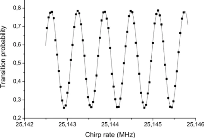
Finally, the phased-locked Raman lasers are used to realize the interferometer. Due to the Doppler effect, the Raman detuning has to be chirped to compensate for the increasing vertical velocity of the atomic cloud. This chirp a, obtained by sweeping the DDS frequency, in-duces an additional phase shift. The total interferomet-ric phase is then given by: ∆Φ = (kef fg − a)T2. Figure 5
displays the interferometric fringes obtained by scanning the chirp rate. In this experiment, T is 40 ms and the sensitivity is already of 4 × 10⁻⁸ g Hz−1/2, limited by
residual vibrations of the apparatus.
Fig. 5. Atomic interferometer fringes obtained by scan-ning the Raman detuscan-ning chirp rate during the interfer-ometer. The time between the Raman pulses is T = 40 ms. The solid line is a sinuso¨idal fit of the experimental points displayed in black squares.
To conclude, this locking technique allowed us to build with only three lasers an optical bench providing the
re-quired frequencies to cool 87RB atoms in a 3D-MOT
and to realize an atomic interferometer with far detuned Raman lasers. Our laser setup is robust and versatile since the lasers routinely stay locked for days and we can change the detuning of the Raman transitions at will. Our goal for the gravimeter experiment is to reach an ac-curacy of 10−9gand a sensitivity of a few 10−9gHz−1/2.
Thanks to its compactness, the gravimeter will be trans-portable to compare it with other absolute gravimeters. It will also be moved close to the LNE watt balance ex-periment, which aims at measuring the Planck’s constant and redefining the kilogram.12
The authors P. C. and J. L. G. thank DGA for sup-porting this work. The author K. T. T. thanks also the ”Fondation Danoise” for its support.
References
1. Ch. J. Bord´e, Metrologia 39, 435 (2002).
2. A. Clairon, Ph. Laurent, G. Santarelli, S. Ghezali, S. N. Lea and M. Bahoura, IEEE Trans. Instrum. Meas. 44, 128 (1995).
3. F. Riehle, Th. Kisters, A. Witte, J. Helmcke, Ch. J. Bord´e, Phys. Rev. Lett. 67, 177 (1991).
4. A. Lenef, T. D. Hammond, E. T. Smith, M. S. Chapman, R. A. Rubenstein, and D. E. Pritchard, Phys. Rev. Lett. 78, 760 (1997).
5. T. L. Gustavson, A. Landragin, M. Kasevich, Class. Quantum. Grav. 17, 1 (2000).
6. A. Peters, K. Y. Chung, S. Chu, Metrologia 38, 25 (2001).
7. M. Kasevich and S. Chu, Phys. Rev. Lett. 67, 181 (1991).
8. P. Cheinet, B. Canuel, F. Pereira Dos Santos, A. Gauguet, F. Leduc, A. Landragin, submitted for publication to: IEEE Trans. on Instrum. Meas., http://fr.arxiv.org/abs/physics/0510197
9. J. L. Hall, L. Hollberg, T. Baer, and H. G. Robinson, Appl. Phys. Lett. 39, 680 (1981).
10. G. Santarelli, A. Clairon, S. N. Lea, and G. M. Tino, Opt. Commun. 104, 339 (1994).
11. K. Dieckmann, R. J. C. Spreeuw, M. Weidem¨uller and J. T. M. Walraven, Phys. Rev. A 58, 3891 (1998). 12. G. Genev`es, P. Gournay, A. Gosset, M. Lecollinet, F.
Villar, P. Pinot, P. Juncar, A. Clairon, A. Landragin, D. Holleville, F. Pereira Dos Santos, J. David, M. Besbes, F. Alves, L. Chassagne, S. Top¸cu, IEEE Trans. Instrum. Meas. 54, 850 (2005).