Design of a Formula SAE Electric Powertrain
by Brian Wanek
Submitted to the
Department of Mechanical Engineering
in Partial Fulfillment of the Requirements for the Degree of Bachelor of Science in Mechanical Engineering
at the
Massachusetts Institute of Technology
June 2017 MASACSTS INSTITUTE OF TECHNOLOGY
JUL 2
5
2017
LIBRARIES
ARCHIVES
C 2017 Massachusetts Institute of Technology. All rights reserved.Signature of Author:
Certified by:
Department of Mechanical Engineering May 19, 2017
Signature redacted
Accepted by:
Amos Winter
Professor of ec nical Engineering Thesis Supervisor
Signature redacted
Rohit Karnik
Professor of Mechanical Engineering Undergraduate Officer
Design of a Formula SAE Electric Powertrain
by Brian Wanek
Submitted to the Department of Mechanical Engineering on May 12, 2017 in Partial Fulfillment of the
Requirements for the Degree of
Bachelor of Science in Mechanical Engineering
ABSTRACT
The design requirements for the new electric powertrain were the ability to deliver the peak power of 80kw allowed by rules and meet the mass goal of 23kg. Rear wheel independence
needed to be maintained either through a multi-motor design or a differential, but with vehicle performance in mind. Stiffness of the mounting system was another goal, as the previous design had lateral deflections larger than deemed acceptable.
Along with system design requirements, various components and packaging options were considered. Preliminary design and estimation coupled with fundamental engineering rational focused the design to a particular setup. In parallel with system design, analysis was performed to select materials, geometry, bearings, and hardware. Load cases were analyzed to determine how FEA simulations would be set up. Failure modes checked were primarily yield conditions, but stiffness of the mounting plates was also analyzed to ensure the system met the max
deflection goal of 0.005".
The final design included a single three phase electric motor capable of up to 100kW peak with a limited slip differential, and a mass reduction of almost 45% over the previous powertrain,
meeting the mass goal. Eccentric rings allow for easy chain tensioning. A simple 6 bolt mounting system makes the self-contained unit easy to remove from the frame, and overall stiffness is improved from the previous design.
Thesis Supervisor: Amos Winter
Table of Contents Abstract 2 Table of Contents 3 List of Figures 4 List of Tables 5 1. Introduction 6 1.1 Competition overview 6
1.2 Relevant Rules and Design Constraints 6
2. System Design 7
2.1 Powertrain Layouts 7
2.2 Motor and Differential Selection 8
2.3 Car Model 8 2.4 Design Iterations 10 2.5 Final Design 11 3. Analysis 14 3.1 Bearing Selection 14 3.2 FEA Analysis 16 3.2.1 Sprocket Adapter 16 3.2.2 Mounts 17 3.3 Mesh Convergence 18
4. Summary and Conclusion 19
List of Figures Figure 2-1: Figure 2-2: Figure 2-3: Figure 2-4: Figure 2-5: Figure 3-1: Figure 3-2: Figure 3-3: Figure 3-4: Figure 3-5: Powertrain Configurations Design Iterations
Chain Tensioning Mechanism Rear View of Chain Position Isometric View of Final Assembly Torque Balance on Bearings FEA Analysis of Sprocket Adapter
FEA Analysis of Mount, Von Mises Stress
FEA Analysis of Mount, Horizontal Displacement Mesh Convergence of Sprocket Adapter
7 11 12 13 14 15 16 17 18 19
List of Tables
1. Introduction
Formula SAE (FSAE) is a collegiate engineering and racing competition where teams from around the country, and the world, build a short-wheelbase racecar to compete in a variety of events at competition each year. In FSAE, weight is critical. Power output of the car is limited, so whenever mass can be removed from a system it benefits the performance of the vehicle. As one of the heaviest and most influential systems of the car, the mass and architecture of the powertrain is very influential on total car mass.
1.1 Competition Background
There are a variety of events at competition, which guide design specifications down a certain path. For instance, the powertrain is limited it 80kW max power output. The events at
competition include an engineering design presentation, a cost of mass-production presentation, a business case, and dynamic events such as the acceleration strip, traction circle, and autocross course. The construction of these events requires the design to not just be an exercise in
optimization of performance, but also cost and manufacturability. This more accurately reflects a real world systems design project.
There are two divisions of this competition, one for internal combustion cars, and one for electric vehicles. The powertrain design focused on in this paper is primarily concerned with the electric vehicle competition. Throughout the design process, decisions will be made based on both good general engineering practice and designing for the specific application of the FSAE competition. As with any engineering project, the application of the system must be kept in mind.
1.2 Relevant Rules and Design Constraints
As mentioned above, there are a number of rules and events in the competition that guided system specifications. The limit of 80kW power output is a large constraint, with a maximum system voltage of 300V. The chain and motor need to be properly guarded with specific materials and dimensions. Certain fastener grades and sizes are required in certain locations, along with proper positive locking. Braking power regeneration is allowed, which is a performance benefit, but limits the list of possible motors [1].
Besides specific rules, another major constraint of the design is that we must be able to
manufacture components in-house or have the ability to easily source the part. Manufacturability will be a factor that drives design decisions throughout the process. Thankfully, access to some of the best machine resources on campus allows for complex parts to be machined, limiting the impact this constraint has on the design.
At competition, the car will need to pass a "rain test" which requires the car to sit above and below sprinklers for two minutes, after which the tractive system of the car needs to function without fault [1]. This impacts the powertrain primarily in the fact that everything will need to have a proper ingress protection rating, at least IP 65. This is defined as being dust tight and
having protection against water jets [3]. This will mainly impact the selection of the motor, but is also a consideration when looking at different transmissions, be it a differential or planetary gearbox.
2. System Design
2.1 Powertrain layouts
The previous powertrain design consisted of two Emrax 228 motors each with a chain drive single gear reduction to independently drive the rear wheels. This system was used as a baseline to which other designs were compared. At the very least the same setup could be used but iterated upon to produce a marginally better system, in terms of mass, stiffness, ease of service and robustness. Baseline metrics of this system are the mass, overall dimensions, and ability to independently control the rear wheels.
Two other system setups were considered, one of which is the two motor design with planetary gearboxes instead of a chain drive. The major benefit of this setup is that the longitudinal length of the assembly is much shorter than the others, allowing for a shorter but wider powertrain compartment in the rear of the frame. Everything is also aligned axially so there are minimal moments on the inner bearing races. The downside is that this would be the widest setup, and includes two complicated, expensive, and potentially heavy planetary gearboxes.
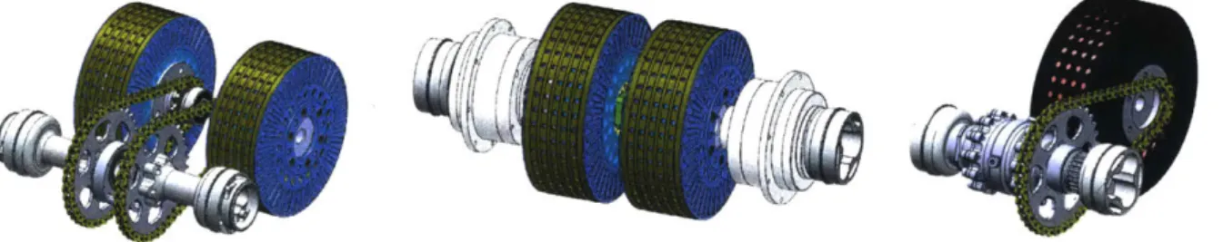
The other system design was a single motor with a chain drive to a limited slip differential. This has the benefit over the other two of being the lightest configuration while still being able to maintain the power output required. It is also the narrowest configuration and in general occupies the least volume in the rear of the frame.
Figure 2-1: The baseline two motor with chain drive configuration (left), two motor with planetary gearboxes
(center), and single motor with chain drive and differential (right). These assemblies serve as very preliminary size estimates to discuss interactions with other sub-teams and determine the best configuration for overall car
performance.
From examining different powertrain layouts and different components for these layouts, a best estimate mass design goal of 23kg was set for the powertrain assembly. This was determined with information from component selection (section 2.2) and car modeling (section 2.3),
selecting the single motor with differential design. This was factored into the total car mass predictions, along with other system mass estimates, to be used in the car model calculations in section 2.3. All of these design choices are recursive, seeing as the car model is required to make a prediction about the best layout and components leading to an expected mass, but then these values are needed as inputs to the car model and to make component selection choices.
2.2 Motor and Differential Selection
While different system configurations and the car model were being analyzed, various motors and transmissions were used in the equations. All of this occurred in parallel to allow for the best possible layout and gear ratio for the available motors and trasnmissions.
Numerous different electric motors were examined, starting with the previously used Emrax series of motors. They come in three sizes, the 208, 228 and 268 allowing for the right sizeing of motor for the specific application. Other companies that were examined included TG Drives, AMK, Yasa, DHX, Thingap and Neugart. Due to the 300V constraint, many high voltage motors are immediately deemed unusuable. A basic metric that was used in comparing motors was the power to weight ratio of the motor, which was very good with the Emrax motors. It was found that at our voltage and power limits, the Emrax motors have the best power to weight ratios. When plugging the different motor models into the car model calculations and looking at overall packaging options, a single Emrax 228 seemed to be our best options, coming in at a power to weight ratio of 8.13kW/kg. They are also rated to IP65, which is a necessary requirement. For transmission research, limited slip differentials and planetary gearboxes were primarily explored. The best differential for this application is an FSAE purpose built limited slip differential from Drexler Motorsport. It has a mass of only 2.6kg and a torque maximum of 1200NM, much more than necessary. The differential is a clutch type, which doesn't have as good of performance or lifetime as a torsen style differential, but is much simpler and accounts for the extremely low mass in this case. The clutch type works by engaging clutches as the speed difference across wheels increases, which will eventually wear out the clutch plates and takes slightly longer to react. Torsen style differentials are pure mechanical linkage and have no wear parts, allowing for longer life and faster response time [2].
Commercially available planetary gearboxes in the torque and speed ranges required turned out to be much heavier, with the lightest options being between 5 and 7 kg from Neugart and TG
Drives. Even in a single motor setup, where using a planetary gearbox doesn't make as much sense, this is still much heavier than the differential and the passive torque control system from the LSD is absent. The selection of the single Emrax 228 and Drexler differential made sense as
a great combination of components that were as light as possible while still providing the performance required.
2.3 Car Model
A simple car model was constructed to determine the gear ratio of the powertrain as well as the max torque and speed that would be required for the motor. This was essential in selecting a motor and occurred in parallel with the layout design process.
The model inputs include max velocity of the car, tire radius, car mass, tire coefficient of friction, center of gravity height, wheelbase, and weight bias. Some of these values were known initially since the components had been selected, while others were the design goals for this year's vehicle. Tire radius was set at r = 0.229m, with a coefficient of friction taken from the tire
data sheet of u = 1.4. Wheelbase was set at lb 1 .524m. Initial design estimates from each system of the car put our mass at m,= 290kg with a rear weight bias Of WbiasO=. 55, and the center of gravity height hcg= 0.279m. The maximum velocity of the car was determined after the maximum acceleration was calculated from the car model.
The model first assumes an acceleration a (in g's) and calculates the weight transfer to the rear wheels from this acceleration using:
a * hcg
mtransfer =* M
1wb
From which the effective mass on each of the rear wheels can be calculated, summing this transferred mass and the static mass (based off weight distribution). After determining total mass per wheel, the normal force each wheel applies to the ground can be calculated, and a maximum theoretical acceleration (in g's) can be determined using:
(mtransfer + Wbias * Mc) * p.
anew =
After determining this acceleration ane,, it can be plugged back into the first equation and
iterated upon to converge to an actual maximum theoretical acceleration amax = 1.036g's. At this point, a few other parameters of the system need to be calculated to allow the selection of a gear ratio given a motor selection.
The maximum velocity of the car during any competition event needs to be determined, which can be done through simple kinematic calculations of a few different scenarios now that a maximum theoretical acceleration has been determined. The first of these is the acceleration event, a 75m straight line drag race from a zero velocity start. Using the kinematic formula:
vf - . = 2
* amax * laccel
the final velocity of the car can be determined, which is vj= 39m/s. It is possible that the car could reach higher speeds on the autocross course, so those conditions need to be checked as well. Although the full layout of the course isn't known until competition, certain parameters are, such as the maximum length of straight after the smallest diameter corner and the largest
diameter comer. For a hairpin turn of minimum diameter 9m, the maximum length straight is 60m. For a wide turn of maximum 45m diameter, the maximum length of straight is 45m. Turns
with intermediate diameters will have intermediate length straight sections afterwards, and so the two extreme cases are examined.
The maximum lateral acceleration of the car is estimated to be 1.5g's from past experience and as a generous upper bound. Using the following formula:
Vexit = alat * rturn
the maximum theoretical exit velocity from the corner can be calculated. Using this exit velocity
as v0, the final velocity at the end of the two straight section scenarios can be calculated. Both the
small and large turn scenarios have vj= 35m/s, within lm/s of one another. This may be the reason behind the selection of turn and straight geometry by the rules committee. From these three cases, the maximum velocity the car can be expected to reach is vm. = 39m/s. This would require a max driveshaft rotational speed calculated using:
Vmax * 60
(L)DS max
tire
which is WDS Max = 1630 RPM.
Another characteristic of the system that will impact the torque output required of the motor is the rolling resistance of the car. This is the force required to keep the car moving at a constant velocity due purely to rolling resistance of the tires on the driving surface, and is defined as:
FRR = N * CRR
where CRR is the coefficient of rolling friction and N is the total normal force of the vehicle. A high rolling resistance coefficient for performance tires is above 0.01 [5]. Due to the nature of the extremely sticky racing slicks we use, a rolling resistance of CRR = 0.02 was used, twice that
of consumer performance tires.
Once all of these values were determined, the driveshaft torque required per wheel could be calculated to then determine the gear ratio required to reach the highest acceleration the vehicle's tires would be capable of. Driveshaft torque required was calculated using:
mc FRR * Rtire
T = 9.81 * amax* -- * tire +
2 2
and was found to be T= 343.4Nm per rear wheel. With a max torque requirement and a maximum rotational speed requirement, the gear ratio can finally be selected.
With a gear ratio of 3.125:1, the maximum torque requirement (sum of both wheels) is 231.3Nm, falling just under the selected Emrax 228's maximum torque specification. At this gear ratio, the motor speed required to reach a driveshaft rotational speed of 1630RPM would be 5091RPM, again falling under the maximum speed specification. This gear ratio puts the motor in the perfect position to perform well in the low end as well as the top end, while still allowing for
some error when applying these calculations to a real system. If the car has a slightly higher or
lower mass than predicted, different cg location, or some other factor is different than modeled, these performance values could be different.
2.4 Design Iterations
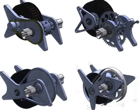
Once components were selected, rough designs could be made to better approximate the size and mass of the system. The first iteration features an absolute minimum mounting system with a configuration of the components that would continue into the final iteration. The motor is mounted at the front of the powertrain, closer to the center of mass of the car, with the
differential behind it, both axes parallel to one another. Two mounting plates run down each side of the assembly which then mount to the frame at six bolting locations. One major downside of this design is that the chain lies outside the left and right bearings, meaning there is a
cantilevered load on the two axles. This was how the differential was designed to accept the chain, but it would be more optimal if the chain could lie between the two axis and remove any cantilevered load.
The second iteration featured a completely split assembly. The reasoning behind this design was that the two halves could be positioned independently from one another, allowing for an easy method of changing the distance between the two axis and thus tensioning the chain after installation. A major issue with this design is that it required the two half mounts to be in the same plane as one another when mounted to the frame such that the chain would be properly aligned. Due to the welding process and past tolerance experience of welding tabs to the frame, this was not something that could be achieved, meaning this design was quickly thrown out.
Figure 2-2: First iteration (top left), second iteration (top right), third iteration (bottom left), and fourth iteration (bottom right). Each is shown with an Emrax 228 and Drexler differential. Mount locations are indicated by the
The third and fourth iteration move back to the unified mount design, with geometry changing as the preliminary frame design changed. A notable feature of iteration three is that the motor is placed extremely low, again to move it as low and forward as possible in the car. Iteration four
still has the motor as low as possible, but frame geometry has changed significantly and the mount locations have been refined allowing for ease of installation. At this point many features of the final design are present, addressed in the next section.
2.5 Final Design
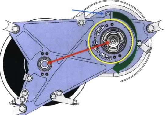
After numerous design iterations and assessing the pros and cons of each, the final design concept was locked in and fully flushed out. Continuous mount plates on either side were used with the chain mounted between the bearings. An eccentric ring was selected as the chain tensioning method, allowing for a compact and easy way to adjust chain tension. This
mechanism works by rotating a circular piece in the mounting plate which has an off-center bore for the bearing. As this piece is rotated, the distance between the two axes, motor and
differential, changes, allowing for different sprocket sizes and properly tensioning the chain after installation. To hold the ring into the desired rotated position, a single bolt at the top of the mount clamps down, tightening the bore in the mounting plate in which the eccentric ring sits.
0
Figure 2-3: Side view of the final assembly, showing eccentric ring tensioning mechanism. Green arrow shows
rotation of the eccentric ring piece (circled in yellow). This rotation causes the change in distance between the axes. indicated with red arrow. The blue arrow indicates the single bolt which clamps the ring into place.
Another notable design feature is changing the intended mounting location of the chain from outside the bearing to within the two bearings, illustrated in Figure 2-4. This minimizes the cantilevered load on the axes and results in a lighter design. To allow for this change, a sprocket adapter had to be designed to allow the sprocket to attach to the housing of the differential. The way the differential is designed, all of the torque from the splined location where the sprocket is
intended to mount is transmitted through the bolted joint in the housing inside the bearing mount location. So by mounting the sprocket here and transmitting torque to the differential at this point, no load paths have changed and the differential should not fail.
I
AI
AI
0 U iuiim.ir
Figure 2-4: Rear view of the powertrain assembly, illustrating design choice on chain location. Red arrow indicates
the differential spline where the sprocket is intended to go, outside the bearing planes represented by the vertical blue lines. The green line represents the new location of the sprocket, bolted to the differential housing seen just to
the right of the chain guard.
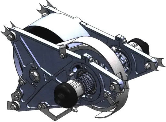
The final assembly mounts to the frame with only six bolts, and is a much tighter package than the previous powertrain design. The chain and motor guards are integrated directly into the package, mounting to the side plates making installation and removal of the powertrain very quick. The bolts to adjust the eccentric rings are easy to access even when installed in the car, along with dowel pin adjustment levers which allow for tools such as screwdrivers to easily
rotate the eccentric rings in the car. The total mass of the system met the design goal of 23 kgs, an extremely important metric when overall car mass is such a critical factor.
Figure 2-5: Isometric view of the final design assembly.
3. Analysis
3.1 Bearing selection
In determining bearing size and type, it is important to identify the load cases that they will experience, the environmental conditions they will be exposed to, and what their required lifetime is. SKF bearings are a well-known name when it comes to bearings, and we have had considerable experience and good results with them, with a huge variety of sizes available. As with the other components of the powertrain, the environmental conditions the bearings will be exposed to are water and dust, so they will need to be properly sealed against the elements. For
SKF bearings, this is the 2RS 1 series designation.
To determine the radial loads each bearing would experience, and simple torque balance was created about the plane the chain occupies as shown below in Figure 3-1.
F ml F mr
R-ml R-mr
Chain tension
R di R d
F-di F-dr
Figure 3-1: Top down view of the torque balance used to calculate bearing load. The vertical line represents the chain, and applies a large tensile load. Torques were balanced using this line as x=O.
From this, radial loads were calculated. Note that Fmr is not a bearing but the fixed mounting of the motor to mount plate. Axial loads in this system are minimal, and are primarily due to lateral acceleration of the motor and differential in the mount system. The other axial load is from the two halfshaft plunger springs, acting inward on the differential axis. Although these will typically be opposing forces with slight imbalances due to different left-right wheel vertical positions, a worst case scenario of one spring completely loaded axially against the powertrain was considered.
To determine the required lifetime of the bearings, a simple breakdown of drive time was created, as shown below in Table 3-1.
Car Lifecycle Analysis
Testing trip drive time 2 hr Competition drive time 2 hr
Testing trips/car 15 trips
Miscellaneous drive time 5 hr
Total time 37 hr/season
Table 3-1: Analysis of time car spends driving in a typical season. Testing trips include any planned outing, during
which the car is typically driven for oniy a single charge of the battery. Miscellaneous drive time includes short tests occurring in the shop on car stands or in the alley. All values are an expected absolute maximum.
With an expected operating time of 37hr/season, and a generous factor of safety of two applied to this value, the bearing should be able to provide about 75 hours of lifetime. To determine the actual lifetime of the bearing under the specific loading conditions, the SKF bearing lifetime
calculator was used. With this calculator, outputs are average lifetime, power loss, and C/P ratio, which is a factor of safety analog in bearing calculations.
For the three different bearings, there were different constraints which ultimately led to
convergence on a specific bearing model. The non-chain side bearing on the differential takes the smallest loading of the three bearings, and thus geometry (specifically inner diameter restriction) led to a selection. For the other two chain side bearings, their selections were again dependent on inner diameter restrictions, but they had to be larger sized bearings to take the large loading they experience from the proximity of the chain tension. All met the requirement of at least 75 hours of expected lifetime.
3.2 FEA Analysis
3.2.1 Sprocket Adapter
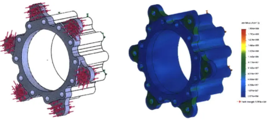
Every high stress part which was designed underwent FEA analysis in SolidWorks to precisely determine geometry of the part. An example of one such part is the sprocket adapter, a piece which mounts the rear sprocket to the differential housing while changing the bolt pattern from 6 %-28 bolts to 12 M5-1 bolts. It also allowed the inner diameter of the sprocket to be larger than the outer diameter of the pressed on bearing, meaning the sprocket could be swapped out without pulling bearings, a difficult process that usually damages the bearing.
Figure 3-2: FEA setup (left) and heat map of Von Mises stress (right) for the sprocket adapter. Due to boundary
effects of fixturing the rear face of the sprocket adapter to the differential, an extrusion was created (shown by wireframe on left) to mitigate this boundary condition. The maximum Von Mises stress in this part is 195 MPa. The
part is made out of 7075 aluminum, resulting in a factor of safety of 2.6.
The analysis setup conditions for this part are relatively simple, but represent a procedure used across all parts. This part is of particular interest due to the interesting boundary conditions that occur and the setup required for bolt clamping. Torque was applied on the front and back face where the sprocket bolt pressure cones clamp, transmitting the torque through frictional shear. A compressive force from bolt preload was added. At the interface between the sprocket adapter
and differential, the entire face was taken as being clamped to the differential. This was done due to the fact that almost the entire area of the interface has a bolt.
As mentioned in Figure 3-2, the factor of safety on this part was 2.6, which is relatively high for a performance application. The final geometry turned out this way because this part represents a case where it was impossible to make it any smaller while fitting all of the bolts in. So a
geometric restriction was reached instead of a yield failure condition.
3.2.2 Mounts
Another part of particular interest in the analysis phase was the mounting plates, because they also had a different design restriction than yield strength. One major improvement that needed to be made over the previous powertrain design was increasing the stiffness of the entire assembly, which is mostly due to the lateral stiffness of the mounting plates. Under loading conditions, it was determined that the entire assembly should not displace more than 0.005".
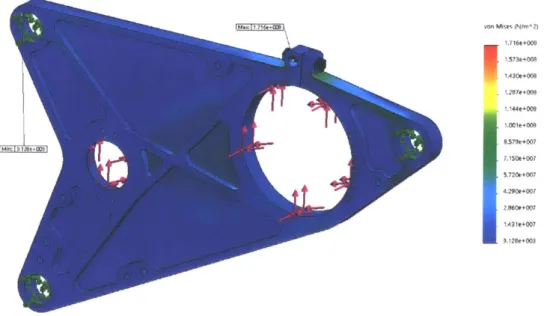
The study was set up on the chain-side mount such that the three frame mounting locations were fixed, and all load cases were applied in a worst case scenario. As shown in Figure 3-3, yielding was not a concern with this part in the final geometry.
von Miss (N/+m2) I1.572e+009 1430e+008 . 1.287e+009 1.144e+009 1.001e+ODB 8.579e+007 7.150e+007 5.720e+007 4.290e+007 2.8960e+007 1A31e+007 9.128e+003
Figure 3-3: Heatmap of Von Mises stress in the chain-side mounting plate. Applied loads are chain tension, lateral
forces due to motor and differential acceleration, bump loading, and halfshaft plunger spring load. Maximum stress was 172 MPa, which results in a factor of safety of 2.84.
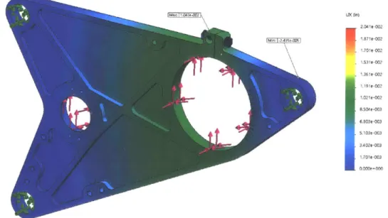
But as mentioned previously, the design constraint with this part was meeting the maximum deflection goal. The same load cases were used, but instead the deflection under load was examined, and geometry adjusted until this value was adequate. The results are shown in Figure 3-4. _X On) 2.041e-002 1.70le-002
E
153le-002 1.361e-002 1.191e-002 1.021e-002 8.504e-003 6.803e-003 5.103e-003 3A02-003 1.701e-003 O.OD0e+000Figure 3-4: Heatmap of the x axis deflection (perpendicular to the plane of the part). Loading conditions are
equivalent to those mentioned in Figure 3-3. Maximum deflection was found to be 0.010". The 0.005" specification applies to the entire system, so applying this goal to a single plate would be overbuilding. Instead, if both plates have approximately the same deflection under
load, with each having approximately the same loading conditions, the stiffness of the system just due to these two plates can be approximated as a linear combination of the two stiffness'. It was found that both plates did have similar amounts of deflection, and because both were around 0.0 10", the total system deflection under load could be approximated to meet the design goal of 0.005".
3.3 Mesh Convergence
For each part that was analyzed using SolidWorks FEA, a mesh convergence study was
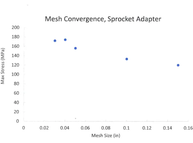
performed to determine if the mesh size was adequate for the geometry being evaluated. In Finite Element Analysis (FEA) a solid body is broken down into much smaller, known geometries. For these studies, these elements are tetrahedrons. As these tetrahedrons become smaller and smaller, the real world case is approached. The limit as the size goes to zero is the actual solution, but clearly this is not a possible computational approach. Instead, the study is iterated many times with reductions in mesh size until the changes in maximum Von Mises stress reach an acceptably low value, i.e. the result is converging to the real solution [4]. As shown in Figure 3-5, the mesh quickly converged to a solution within five iterations.
Mesh Convergence, Sprocket Adapter
0
9
0
0 0.02 0.04 0.06 0.08
Mesh Size (in)
0.1 0.12 0.14
Figure 3-5: Mesh convergence study of the sprocket adapter component. Mesh size started at a large 0.15 inch value
and was reduced incrementally until the subsequent step was relatively close to the previous. Mesh sizes of 0.04 and
0.03 inches were found to have nearly identical maximum Von Mises stress of 175Mpa.
4. Summary and Conclusion
This paper has provided a comprehensive summary of the design process for an electric
powertrain for an FSAE car. The process begins with very basic configurations, allowing system metrics to be estimated and interactions with other systems to be determined. Components can be
selected based on initial requirements, and models can be built to see how these components will perform. All of these steps happen in parallel, iterating upon designs and component selections until an optimization is reached.
Once the fundamental design and components have been selected, more rigorous design can occur in parallel with analysis. This includes component selection like bearings and other load bearing components. Iterations are critical, allowing new design decisions based off faults of old designs, and input from interactions with other systems. While this is occurring, it is critical to meet design goals set up at the beginning of the design process.
200 180 160 140 120 100 80 0L 4-' X 60 40 20 0 0.16 NK- I'm
Ultimately, the final powertrain design is produced. The overall system met the mass goal of 23kg. Ease of installation was addressed with only six mounting bolts in easy to access locations and ease of use was addressed with simple chain tension adjusting. The maximum system deflection issues previously seen were addressed with stiffer mounting plates. Overall, the designed system was able to meet every design goal, which is a successful design. After
manufacturing is completed, in-depth testing can occur to validate design decisions and lead into the next vehicle iteration.
5. Bibliography
[1] "2017-18 Formula SAE Rules." (n.d.): n. pag. 2 Sept. 2016. Web. 25 Apr. 2017.
[2] "Engineering Explained: The Best Kinds Of Differential And What's Most Suitable For You." Car Throttle. Car Throttle, 24 Dec. 2015. Web. 30 Apr. 2017.
[3] IEC 60529, "degrees of Protection Provided by Enclosures (IP Codes)," Ed. 2.1 (Geneva: International Electrotechnical Commision, 2011)
[4] "The Importance of Mesh Convergence." NAFEMS. N.p., n.d. Web. 02 May 2017.
[5] "Tires and Passenger Vehicle Fuel Economy." (n.d.): n. pag. Transportation Research Board, 2006. Web. 2 May 2017.