Design and Analysis of the SmartWalker, a Mobility Aid for the Elderly by
Matthew J. Spenko BS Mechanical Engineering Northwestern University, June 1999
Submitted to the Department of Mechanical Engineering in Partial Fulfillment of the Requirements for the Degree of
Master of Science in Mechanical Engineering at the
Massachusetts Institute of Technology June, 2001
©2001 Massachusetts Institute of Technology All rights reserved
Signature of Author_""~-+---=-"'---_ _ _ _ _ -¥--F--=-"""':;""--Jo::::~ _ _ _ _ _ _ _ _ _
1
/I//De;~me;'
of Mechanical EngineeringV
June, 2001Certifiedby---~~~~l---St-e-v-en--D-u-b-O-w-s--ky
Professor of Mechanical EngineeringThesis Supervisor
Accepted b y - - - -... ;;;;;IIIIfI""E5o'iIoooo"-e=e::...:w====---Ain A. Sonin
A.FiI
Chairman, Departmental Graduate Committee·
CHIV~S
MASSACHUSETTS INSTITUTE
I
_ OF TECHNOLOGY--
I JUL 1 6 2001 l- IDesign and Analysis of the SmartWalker, a Mobility Aid for the Elderly
by
Matthew J. Spenko
Submitted to the Department of Mechanical Engineering on June, 2001 in Partial Fulfillment of the
Requirements for the Degree of Master of Science in Mechanical Engineering
ABSTRACT
In the near future, the baby boomer population will cause a growth in the number of people entering nursing homes. Currently, if people wish to stay out of a nursing home, they must hire a personal aid to take care of daily tasks. A more cost-effective method could be to employ a robotic aid to help with these chores. One such aid is the SmartWalker, a robotic device that would provide health-monitoring sensors, physical support, and help in mobility to the elderly. The focus of this thesis is the design and analysis of the SmartWalker hardware.
The design tools necessary to prevent the SmartWalker from slipping, tipping over, and experiencing brake failure are presented. Furthermore, a study of the omnidirectional platform used on the SmartWalker is performed for uneven terrain. It is shown that all of the wheels of the platform touch the ground at the same time. A simulation of a split caster mobility module, the main component of the omnidirectional platform, traversing a bump is also done. This proves that the control algorithms designed for a perfectly flat floor will suffice on an uneven floor. In addition, this thesis discusses the mechanical design that is necessary to build the SmartWalker. The mechanical design focuses on the split caster mobility modules, the slip rings, the frame, and the tradeoffs between strength and weight.
Thesis Supervisor: Dr. Steven Dubowsky
ACKNOWLEDGMENTS
First and foremost, I would like to thank my parents for their support. In addition I would like to thank Professor Steven Dubowsky for his guidance and the Home Health Care Consortium for their financial support of the project. Thanks also to the members of FSRL during the past twenty months, especially Adam Skwersky and Haoyong Yu for their help with debugging the walker.
Table of Contents
1 Introduction...8
1.1 M otivation for PAM M ... 9
1.2 Literature Review ... 10
1.3 PAM M System Concept ... 13
1.4 First Generation Prototype, the Sm artCane... 14
1.5 Second Generation Features... 15
1.5.1 Battery Life ... 15
1.5.2 Added Support... 16
1.5.3 Health M onitoring Capabilities ... 16
1.5.4 Omnidirectional Platform ... 16
1.6 SmartW alker Design Goals... 17
1.7 Conclusions ... 18
2 O m nidirectional Platform Design and Analysis...19
2.1 Split Caster Mobility Module Analysis for Uneven Terrain...19
2.2 Proof that All Wheels Touch the Floor at the Same Time...22
2.3 Analysis of the Control System Designed for a Flat Floor Applied to an Uneven Floor ... 27
2.4 Simulation Parameters ... 31
2.4.1 Sim ulation Program Structure ... 32
2.4.2 Sim ulation Results ... 33
2.5 Conclusions ... 36
3 Sm artW alker Stability ... 37
3.1 SmartW alker Frame Configuration ... 38
3.2 Slipping ... 39
3.3 Tip-Over ... 42
3.4 Brake Failure ... 45
4 M echanical Design ... 47
4.1 W heel Design ... 48
4.2 Housing Design ... 49
4.3 Slip Ring Design... 51
4.4 Bearing and Axle Design ... 56
4.4.1 Bearing Design ... 56
4.4.2 Axle Design... 60
4.5 Shaft Analysis... 60
4.6 Determining the Proper M otors... 62
4.7 Frame Design... 68
4.8 Conclusions ... 70
5 Sm art W alker Experim ental Evaluation ... 71
5.1 Power Requirem ents ... 71
5.2 M otor Response ... 73
5.3 Sm artW alker Time Response ... 74
5.4 Path Following... 77 5.5 Conclusions ... 77 6 Conclusion ... 79 6.1 Contributions ... 79 6.1.1 Omnidirectional Platform ... 79 6.1.2 Stability ... 79 6.1.3 M echanical Design ... 79
6.1.4 Experim ental Results ... 80
6.2 Suggested Further W ork ... 80
W orks Cited...81
Appendices: A Analysis of a SCMM Traversing Uneven Terrain ... 83
List of Figures
Figure 1-1: SmartWalker Conceptual Drawing (Dubowsky, 2000) ... 8
Figure 1-2 (a,b): Care-o-Bot and PAMM-AID (Schraft, 1998; Lacey, 1998)...11
Figure 1-3: Power-Assisted Walking Support System for the Elderly (Nemoto, 1998)... 12
Figure 1-4: Omnidirectional Wheelchair (West, 1997)...13
Figure 1-5: PAMM System Concept (Adapted from Dubowsky, 2000)...14
Figure 1-6: Physical Layout of the SmartCane (Dubowsky, 2000)...15
Figure 1-7: Movements Necessary for Holonomic and Non-Holonomic Mobile Platforms ... 17
Figure 2-1: General Omnidirectional Platform...20
Figure 2-2: Ground Contact of SCMMs on Flat and Uneven Terrain ... 20
Figure 2-3: Types of Suspension... 21
Figure 2-4: Added Joint to SCM M ... 21
Figure 2-5 (a,b): Minimum Requirements for ODP and Complete ODP...21
Figure 2-6: Inertial Reference Frame ... 22
Figure 2-7: SCM M on Uneven Terrain ... 23
Figure 2-8: Configuration Space of the Second SCMM ... 24
Figure 2-9: Configuration Space of Second SCMM without Added Joint...24
Figure 2-10: ODP in Various Degrees of Uneven Terrain...25
Figure 2-11: Ground that is too Rough for SCMM...25
Figure 2-12: SCM M N otation...26
Figure 2-13: Notation of Various Points on the SCMM ... 27
Figure 2-14: Explanation of Various Dimensions ... 27
Figure 2-15: Explanation of Notation... 28
Figure 2-16: Euler's A ngles... 29
Figure 2-17: Bump Used for Simulation ... 31
Figure 2-18: Diagram of Simulation Program Structure...32
Figure 2-19: Three Dimensional View of the Position of the Wheels and Point D...33
Figure 2-20: Top Down View of the Position of the Wheels and Point D...34
Figure 2-21: V elocity of Point D ... 35
Figure 2-22: Velocity of Wheels One and Two...35
Figure 2-23: Deviation vs. Bump Height ... 36
Figure 3-1: Types of Wheeled Walkers on the Market (Walk Easy)...37
Figure 3-2 Possible Frame Configurations for the SmartWalker ... 38
Figure 3-3: Diagram of Four-Wheeled Passive Walker (Adapted from Finkel) ... 39
Figure 3-4: Free Body Diagram of 2-D Walker...40
Figure 3-5: Forces That Cause the SmartWalker to Slip (Varying Masses) ... 41
Figure 3-6: Contact Polygon... 42
Figure 3-7: Numbering Diagram of the Omnidirectional Platform's wheels ... 43
Figure 3-8 (a,b): Two Different Convex Contact Polygons ... 44
Figure 3-10: Free Body Diagram for Braking ... 46
Figure 4-1: Photograph of the SmartWalker...47
Figure 4-2: Wheel Profiles and Composition (Adapted from Bachman, 1997)...48
Figure 4-3: SC M M H ousing ... 49
Figure 4-4: Worm and Drive Belt Gearing Systems ... 50
Figure 4-5: Electrical Diagram and Possible Places to Put Slip Rings ... 52
Figure 4-6: Slip R ing D iagram ... 52
Figure 4-7: Slip R ings ... 53
Figure 4-8: Resistance of Slip Rings at Various Angles ... 54
Figure 4-9: Problems That Some of the Slip Rings Have ... 55
Figure 4-10: Wheel, Gear, and Axle Diagram...56
Figure 4-11: W heel, Gear, and Axle ... 56
Figure 4-12: Diagram of Bevel Gears (Adapted from Shigley, 1989)...57
Figure 4-13: Components of Force Acting on Gear Tooth (Shigley, 1989)...57
Figure 4-14: Bevel Gear and Bearing Free Body Diagram...58
Figure 4-15: Eccentric Load, its Equivalent, and a Shaft Being Bent by an Eccentric Load (Shigley, 1989)... 61
Figure 4-16 (a,b): Encoder Shaft and Cross-Sectional Area of Encoder Shaft ... 62
Figure 4-17: Wheel Speed (Adapted from Yu)...63
Figure 4-18: Motor Speed vs. Wheel Speed...65
Figure 4-19: Walker Speed and Current vs. Motor Torque (Adapted from Maxon, 1999) ... 6 6 Figure 4-20 Rolling Friction (Adapted from Beer, 1998) ... 67
Figure 4-21: Sm artW alker Fram e ... 68
Figure 4-22: Slip Ring Being Inserted into Frame ... 68
Figure 4-23: Star Linear Extruded Aluminum (Rexroth Star)...69
Figure 4-24: Diagram of Frame Cutaway...69
Figure 5-1: Current Used by Computer at Startup ... 72
Figure 5-2: Theoretical vs. Actual Current Use at Full Processor Speed...72
Figure 5-3: Velocity Profile of M otors... 73
Figure 5-4: Normalized Motor Response ... 74
Figure 5-5: Experim ental Setup ... 74
Figure 5-6: Distance, Velocity, and Acceleration vs. Time ... 75
Figure 5-7: Approximate Step Response of System ... 76
Figure 5-8: Bode D iagram of W alker...76
Figure 5-9: SmartWalker Following a Path...77
Figure B-1: 2-D Representation of Contact Polygon (Adapted from Papadopoulos, 1996) ... 87
Chapter
1
Introduction
There are three major contributions of this thesis. The first is the realization of the concept of the SmartWalker, a mobility aid for the elderly (see Figure 1-1).
Microphone and Speakers Contact Health for Voice Communication Sensors
Communication and Location Beacon
Computation
Module Navigation and Obstacle Avoidance Module
Mobility Mechanisms
Figure 1-1: SmartWalker Conceptual Drawing (Dubowsky, 2000)
The SmartWalker is comprised of several modules that each perform a separate task. The mobility mechanisms provide the omnidirectional control of the platform. The computation module houses the computer. The communication and location beacon transmits information to and from a central computing facility. The microphone and
SmartWalker. The health sensors acquire data about the user's physical condition. Finally, the navigation and obstacle avoidance module houses sensors that allow the SmartWalker to maintain its course. The second contribution of this thesis is an analysis of the omnidirectional mobility platform used on the SmartWalker. Showing that the omnidirectional platform can be used on an uneven ground and implementing such a device is one of the chief technical challenges of the SmartWalker's design. The last contribution is the results of tests performed on the SmartWalker.
This thesis is divided into six chapters. The first deals with the motivation for the project, background literature, the system concept, and general design issues. The second chapter focuses on the omnidirectional platform used on the SmartWalker. It contains an analysis of the platform's capabilities on an uneven floor. The third chapter discusses the stability of the SmartWalker. This mainly focuses on what forces and conditions would result in the walker slipping, tipping over, or experiencing brake failure. The fourth chapter contains the details of the mechanical design. The fifth chapter shows the results of some of the tests that were performed on the SmartWalker. Finally, the last chapter contains conclusions and ideas for future work in this area.
1.1 Motivation for PAMM
Studies have shown that approximately twenty to thirty-three percent of all nursing home patients do not receive the level and type of care that best serve their needs (Barton, 1997). Furthermore, prolonging the time before an elderly person enters a nursing home can save up to $75,000 a year. Along with the dilemma of increased expenses, many elderly express their desire to not move into nursing homes. With approximately seventy-five million baby boomers about to enter retirement, there is a clear need to develop some way to keep the elderly out of nursing homes for as long as possible (Schneider, 1999).
When elderly people experience a need for help with daily activities, a common occurrence is for them to move into an eldercare facility. These residencies allow their inhabitants to live in their own apartments, but the facility provides meals, health care services, and daily activities. When the elderly encounter such needs as described in
Table 1-1, which currently require the help of a nurse or aid, it is common to move them from the eldercare facility to a nursing home.
Table 1-1: Physical and Cognitive Needs of the Patient (Dubowsky, 000)
Need Physical Deficiency Cause
Guidance Failing memory, Senile dementia,
disorientation Alzheimer's
Physical support Muscular/ skeletal frailty, Osteoporosis, Diabetes, instability Parkinson's Disease,
Arthritis, lack of exercise, failure of Vestibular organs Health monitoring Poor cardiovascular Poor diet, old age, lack of
function, susceptibility to exercise, illness (e.g. flu or strokes and heart attacks pneumonia)
Medicine or other Need to take a variety of Senile dementia, general scheduling medicines coupled with health failure.
failing memory and disorientation
Instead of using people to help with these tasks, a class of robotic devices, called PAMM for Personal Aid for Mobility and Monitoring, could be utilized (Dubowsky, 2000). The PAMM systems would provide health-monitoring sensors, physical support, and assistance with mobility. A PAMM system could delay the transition into a nursing home by taking care of the needs of Table 1-1, thus allowing the person to stay at an eldercare facility. One type of a PAMM system is the SmartWalker, whose design and analysis is the focus of this thesis.
1.2 Literature Review
The design of the SmartWalker covers a wide range of topics, and literature exists on each of these. The topics include the following:
* design of conventional walkers for the elderly * robotic aids for the elderly
* mobility aids for people with various ailments
" omnidirectional wheels and platforms.
Work on conventional walkers is useful for its analysis on stability. The literature on robots that help the elderly describes what other researchers are doing in the field. In addition to robotics for the elderly, there are numerous robots that aid people with other
ailments such as blindness. These robots have features that are useful in designing the SmartWalker. Furthermore, the SmartWalker employs an omnidirectional platform for reasons that will be discussed later. The design of such a platform is complex, and knowledge of the numerous current designs along with their advantages and disadvantages is a necessity.
The design of passive walkers has been largely left untreated. There has been some work done concerning stability and the forces that a four-wheeled walker with a seat encounters when a user attempts to rise from a seated position (Finkel, 1997). The work is a good basis for understanding how and why walkers fail to maintain a stable posture.
In recent years there has been a growing interest in the research community to apply robotic technologies to develop intelligent assistive devices for the elderly. The Care-O-bot (see Figure 1-2a) and the Nursebot have been developed for elderly living in private homes (Schraft, 1998; Baltus). The Care-O-bot is intended to be a mobility aid, do household jobs, and provide communication and entertainment functions. This system is in the early stages of development. The Nursebot project focused on studying and enhancing how a robot interacts with a person, including work on human-machine interface methods, tele-presence via the Internet, speech interface, and face tracking. In addition to those two, the PAM-AID (see Figure 1-2b) and the German RoTA are experimental systems developed to aid the visually impaired elderly with mobility (Lacey, 1998; Mori, 1998). None of these projects attempt to deal with the specific issue of providing a comprehensive mobility aid and health-monitoring device for the elderly.
Other work has focused on the specific problem of mobility in the elderly. The Power-Assisted Walking Support System (see Figure 1-3) is being developed at Hitachi to help support elderly people standing up from bed, walking around, and sitting down (Nemoto, 1998). This device attempts to aid the elderly with all forms of mobility, while the PAMM concept focuses on aiding with ground locomotion only.
Figure 1-3: Power-Assisted Walking Support System for the Elderly (Nemoto, 1998)
There is another device being developed to assist the elderly in mobility (Miyawaki,
1997). It consists of a powered mobile platform that a user can drive but lacks
health-monitoring capabilities or the omnidirectional platform of PAMM.
There has also been substantial work done in the area of robotic wheelchairs. One such wheelchair (see Figure 1-4) has been developed with omnidirectional capabilities (West, 1997). Although this device would be useful for those with severe physical limitations, it is not well suited for the elderly who can still walk. In general, most people use walkers until it is physically impossible for them to walk anymore.
Figure 1-4: Onmidirectional Wheelchair (West, 1997)
One of the main characteristics of the SmartWalker is its omnidirectional platform.
Currently there are numerous designs for omnidirectional wheels and platforms (West,
1997; Ferriere, 1998; Muir, 1987; and Yu, 2000). These devices can be divided into two
categories, those that employ traditional wheels in unique configurations, and those that use specially designed wheels.
One of the SmartWalker's requirements is that it can be used on a wide range of floors and conditions. It needs to be able to traverse tile, short weave carpet, and in dirty areas. Specialty wheels are usually more complex than conventional wheels, and for that reason they tend to become clogged with dirt more easily. Furthermore, although some specialty wheels could be used on a variety of surfaces, they are too bulky to be incorporated into the SmartWalker. For these reasons, an omnidirectional platform that utilizes conventional wheels is used for the SmartWalker.
Although the aforementioned background work covers a wide variety of subjects, each one of them is necessary for the design of the SmartWalker.
1.3 PAMM System Concept
A conceptual diagram of a generic PAMM system providing support and aiding in
the mobility of an elderly user is shown in Figure 1-5. Some of the features of the PAMM system include a 6 axis-force/torque sensor that acts as the input of the user's intentions, a sonar array used to detect obstacles, a vision system that reads signposts on the ceiling to help with localization, health-monitoring sensors, and a way to
communicate with a central computer facility. The P AMM' s computer and the facility's computer would share such information as navigation routes, the patient's schedule, medical instructions, the patient's location and health status, and any patient requests (Dubowsky, 2000).
i
Centralco~puterfacility
I
i Global facIlity map ••••••••••••••
i Patient profile ••••••
I Medical instructions ••••
1. _ _ ... _ _ ..•.. _ _ _ .... _._ .. _._ .. _ ... _ _ . _ •.... _ ...•. " .. _._ •
\ Signposts on I
\ ceiling for localization I
\ I \ I \ I \ / Vision system
~
.
·
·
·
·
·
Navigation info •••• Schedule info ~ Medical instructions \ I for localization I·
·
·
·
·
·
·
·
.
• •.
•.
•. .
• e • •• •• ••.
....
.....
Patient location •••••••••••••• Health status dataPatient requests \ \ \ I I I I I Sonar array to detect obstacles
))
)
PAMM with force/torque
sensor to read Obstacle
user's commands
and health monitoring sensors
Figure 1-5: PAMM System Concept (Adapted from Dubowsky, 20(0)
1.4 First Generation Prototype, the SmartCane
The first implementation of the PAMM system was the SmartCane (Dubow sky, 2000). Its physical design is shown in Figure 1-6. Its main features include a six-axis force/torque sensor to read the user's input, a PCI04 based computer system, skid steering, CCD camera for localization, and a sonar array for obstacle detection. Field trials at eldercare facilities were performed to assess the usefulness of the SmartCane (Godding). One of the observations that resulted from these sessions is that some of
people who could benefit from the intelligent features of the PAMM systems need more support than the cane can offer. Thus, the development of the SmartWalker was initiated.
CCD camera
Acoustic
sensor array
6 axis force/torque
sensor 0 133 Mhz PC104+
DC/DC DOS based computer
converter 13Wh NiCd
battery x2
Motors with PC104+
optical encoders
0
expansion cardsFigure 1-6: Physical Layout of the SmartCane (Dubowsky, 2000)
1.5 Second Generation Features
The SmartWalker uses some of the same features as the SmartCane. The SmartWalker also augments these with a longer battery life, added support, health-monitoring capabilities, and omnidirectional movement.
1.5.1 Battery Life
In order to achieve a longer battery life, the SmartWalker employs pulse-width modulation (PWM) as opposed to linear amplifiers to control the motors (Kozono, 2000).
A linear amplifier works by outputting an attenuated source voltage, which results in
wasted power. PWM amplifiers work by rapidly switching between allowing all of the voltage through and none at all. This way a PWM amplifier can achieve close to ninety-five percent efficiency compared to the approximately twenty percent of a linear amplifier (Tal, 1976). In addition the PWM amplifier has the added benefit of being smaller and lighter than a linear amplifier.
1.5.2 Added Support
A study by the Center of Disease Control found that 25.2% of the population in
nursing homes uses walkers (Gabrel, 2000). Thus, the SmartWalker provides the intelligent features of PAMM to a percentage of the elderly population that requires more support than a cane can furnish.
1.5.3 Health Monitoring Capabilities
The walker also incorporates sensors that monitor a user's pulse. This was not possible on the SmartCane because it only has one handle, and two handles are required. More detailed information about the SmartWalker's health monitoring capabilities can be
found in other literature (Darrigo, 2001).
1.5.4 Omnidirectional Platform
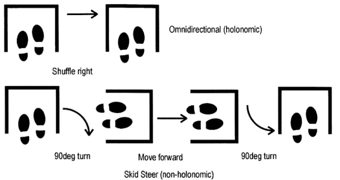
The walker is inherently larger and bulkier than a cane. Thus, a skid-steer drive mechanism on the walker would greatly reduce its mobility. To create a system with as much maneuverability as the SmartCane, an omnidirectional mobility platform is needed. The benefits of an omnidirectional system are clear. For example, a user trying to sit in a chair that is directly on his right would easily be able to shuffle to his right using an omnidirectional system. However, if the walker has a skid-steer drive, then the user would need to rotate ninety degrees clockwise, move forward, and then rotate ninety degrees counterclockwise (see Figure 1-7). Therefore, the omnidirectional platform development is vital.
il
w
F
Omnidirectional (holonomic) Shuffle right11!1
4*OP
K
171
0
90deg turn Move forward 90deg turn
Skid Steer (non-holonomic)
Figure 1-7: Movements Necessary for Holonomic and Non-Holonomic Mobile Platforms
1.6 SmartWalker Design Goals
The first step in designing the SmartWalker was developing a set of design parameters and goals, which along with their justifications are shown in Table 1-2 through Table 1-4.
Table 1-2: Environmental Parameters
Facilities Indoor
Floor Tile or thick weave carpet
Ramp Less than 5 degrees
Light Normal conditions
Table 1-3: Mechanical Goals
Width ~ Standard walker's width
Length < 1.5 times a standard walker's length
Height Adjustable
Weight Less than 25 kg
Speed 0.4 m/s maximum
Mobility Omnidirectional
Vertical loading - 55 kg
Battery life One charge per eight hours
Design Modular so it can be reconfigured
Safety measures Emergency brake, collision detection, acceleration detection
Table 1-4: Communication and Control Goals
Authority Shared between the user, PAMM, and the
central facility computer
Planning and control system Onboard
Localization Able to fully locate after each start,
frequent enough for accurate motion control
Acoustic obstacle avoidance and Able to detect and avoid new obstacles at
recognition least 4 meters away
Control accuracy < 15 mm in localization error per 1 m I< 10 deg. angular error per 1 m
1.7 Conclusions
This chapter described the concept of the PAMM project as well as early steps in the design of the SmartWalker. The chapter also introduced the SmartCane, the first prototype of a PAMM system. Furthermore, this chapter supplied the background literature necessary to properly design the SmartWalker. Perhaps most importantly, the motivation behind the PAMM project was also presented in this chapter.
Chapter
2
Omnidirectional Platform Design and Analysis
One of the main challenges in this project is the design and implementation of the omnidirectional platform. This chapter details the analysis of such a platform, which is based on a previous design (Yu, 2000). The first part of the chapter shows what the omnidirectional platform looks like and why an analysis needs to be done for uneven surfaces. Why the platform is omnidirectional can be found in other literature (Yu, 2000). The next section of this chapter proves that all the wheels maintain contact with the ground. The third part of the chapter derives the equations of motion for an uneven floor. Finally, the fourth part of this chapter shows the results of a simulation of a split caster mobility module, the basis of the omnidirectional platform, traversing a bump. This simulation demonstrates that the platform's control algorithm, which is designed for
a flat surface, will perform adequately on an uneven floor.
2.1 Split Caster Mobility Module Analysis for Uneven Terrain
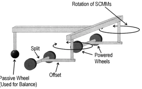
The type of omnidirectional platform (ODP) that is used on the SmartWalker consists of two split caster mobility modules (SCMM), a bar linking the two together, and at least one additional wheel used for support (Yu, 2000). The four powered wheels make up two split caster mobility modules (see Figure 2-1).
Rotation of SCMMs
Si owered
0 , Wheels
Passive Wheel Offset (Used for Balance)
Figure 2-1: General Omnidirectional Platform
In order to ensure that control algorithms will work properly, each of the powered wheels must maintain contact with the floor at all times. If the floor is uneven, then the SCMMs will loose contact with the ground. This is evident by examining Figure 2-2. It shows a two-dimensional image of the omnidirectional platform as if one were looking at it from ground level. In the top part of the figure, the floor is level and there is no problem with the wheels maintaining contact. The bottom part of the figure shows an uneven surface and demonstrates that one of the wheels fails to make contact.
No contact
Figure 2-2: Ground Contact of SCMMs on Flat and Uneven Terrain
To overcome this problem, a suspension is added to the wheels. Two possible suspensions, independent and pivot, are shown in Figure 2-3.
Independant Pivot
Figure 2-3: Types of Suspension
For simplicity the pivot suspension is used on the SmartWalker. It consists of a passive joint added at point C (see Figure 2-4), and it allows member
@,
the encoder shaft, to rotate freely about the u-axis.z
w
U
Figure 2-4: Added Joint to SCMM
The arrows in Figure 2-5a show the rotation of the SCMMs now that the pivot joint has been added.
For the SmartWalker, two passive casters with spring suspensions are used in the rear of the platform to maintain stability (see Figure 2-5b).
A closer look at the omnidirectional platform traversing an uneven terrain poses
two questions:
1. Is contact with the ground guaranteed at all times?
2. Do the added joints to the system cause any undesirable motions or cause the platform to veer too far off the intended path?
2.2 Proof that All Wheels Touch the Floor at the Same Time
The first question will be answered by showing that all of the wheels of the walker can and do touch the surface of an uneven terrain at the same time. This is done in three steps:
1. It is shown that the two wheels of one SCMM touch the ground.
2. Then, with the first SCMM set in place, it is shown that the configuration space of the second SCMM's wheels lies on the ground.
3. Finally, it is shown that any passive casters can touch the ground if they have
independent suspensions.
It is assumed that the wheels are modeled as thin disks. All dimensions are with respect to an inertial reference frame (see Figure 2-6). It must be noted that the two wheel contact points do not necessarily lie along a line that is parallel to the axle. However, this analysis is constrained to a slightly uneven floor, and thus it is assumed that the two wheel contact points do lie along a line that is parallel to the axis. All the figures in this section represent rough terrain in order to clarify dimensions and make the figures easier to read.
F Y
Given a point on the surface of the ground:
P(xI, yI,z1
)
(2-1)Choose a second point, P2, to lie in the same plane, Pxz, as P1, such that P2 is represented
as:
P2(x2, Y1, z2) (2-2)
With the constraint that
d = (x2 - X1 )2 + (z2 -zI)2 (2-3)
where d is the length between the two wheels (see Figure 2-7).
d Za Wheels Axle P3(x3,y1,z3) P2(x2,y1,z2) P1(x1,y1,z1)
Figure 2-7: SCMM on Uneven Terrain
Inside the x-curve, the curve of intersection of z = f(x, y) with a vertical plane
parallel to the xz-plane, yi can be taken to be a constant, such that the ground can be represented by z = f(x) (Edwards, 1994). Given x, and the function that represents the
height of the ground,
z=
f (x)
(2-4)it is possible to find zi. Knowing x, and z, and utilizing Equations (2-3) and (2-4) it is possible to determine the location of point P2. If the two points P and P2 can exist on the
x-curve, then the point P3(x3,b,z3), which is the location of the joint in the SCMM, also
If the wheels of the SCMM are fixed in space and the point P3 is shifted along the Y-axis by a distance s, the offset length of the SCMM, then the position of point C (see Figure 2-8) is determined. Using the equation of a sphere it can be shown that from point
P3, the configuration space of the point P'(x, yf, Z), the point on the second SCMM
corresponding to P3, is bounded by the following inequality:
(h-
s)2 )2 +() (y, _y1 + S))2+(z
-z 3 )2 (h+
s)2
where h is the length of the bar that attaches the two SCMMs.
fz
(2-5)
P3'
N
Figure 2-8: Configuration Space of the Second SCMM
This can be compared to the configuration space of a platform had contained any joints, which is defined by the following inequality:
(h-s)
2 (xI -x3)2 +(y -
(y,+s))
2(h+s)
2This is shown graphically in Figure 2-9.
it not
(2-6)
As one can see, the configuration space for the SCMM without the suspension lies in a plane, while the configuration space for the design with the suspension lies within a sphere. As long as the terrain exists inside of the configuration space, which is true for all cases except when the terrain is a sphere with a radius less than (h+s), then the point
P3 can exist at any height above the terrain. If that is the case, then the two points P' and P can also exist. This is possible because given P1, it is possible to find P2 and P3.
Applying the converse, given P3j it is possible to find Pj' and P. Thus, all four wheels
of the two SCMMs can touch the ground at the same time on an uneven terrain.
This is easily shown graphically for the simple case of points P3 and P lying in
the same x-curve, such that y, = y'. This is equivalent to reducing the configuration
space to a circle of radius h. This is shown in Figure 2-10. Obviously the terrain on the right would be unreasonable for the SmartWalker, but nonetheless it exemplifies the proof.
SCMM 1I
MMS
Figure 2-10: ODP in Various Degrees of Uneven Terrain
There are a few restrictions for the analysis to hold true. It is necessary to make sure that the terrain does not interfere with the axle of the SCMM as shown in Figure 2-11.
This is accomplished by imposing the following constraints on the function that describes the ground, z = f(x). Note that these constraints are only valid for the general case where the axle is a considered a thin line. Actual designs of the SCMMs would naturally require the axle to have a certain diameter and have additional material to hold the axle bearings. This would require modifications on this general case.
Z (x1,z1 + r/cos(O) r P2(x2,y1,z2) P1(x1,y1,z1) E I(x1,O) (x2-r sin(9),O) (X2, 0) Figure 2-12: SCMM Notation For the case where 0 > 0 (see Figure 2-12):
z ! tan 0 x-x1 + ir 0 + Z for
{xi
< x < x 2-rsin 0} (2-7)z<-cotO(x-x 2)+z 2 for{x2-r sin O< X < x2} (2-8)
For the case where 0 < 0:
z! cotO(x -x)+ z for
{x
1 < x<x 1 + rsin 0} (2-9)r
z < - tan 0(x -x 2)+ z2 - for {x + r sin 0 < x < x2} (2-10)
cos0
It is assumed that any additional passive casters belong to the same plane as the SCMMs. The coordinates of passive caster i are (ui, vi, w0+li) where ui and vi are static values that are related to the geometry of the ODP, w0 is some nominal value related to the ODP's frame, and li is the extension of the spring (Simeon, 1993). This shows that the passive casters can also maintain contact with an uneven floor. Thus, all of the wheels of the ODP touch the ground at all times.
2.3 Analysis of the Control System Designed for a Flat Floor
Applied to an Uneven Floor
This section derives the equation that describes the velocity of a SCMM traversing an uneven floor in three dimensions. A simulation is done to show that a
SCMM running over a bump in the floor will not significantly deviate from the desired
path.
The base plane, 9%ase, is considered to be the "flat floor" and is defined by z = 0,
where the gravity vector n =
[0,0,-iY
is normal to Yase. The encoder shaft (the shaft between points C and D in Figure 2-13) of the SCMM is assumed to always be normal toYase. This ensures that nEncoderSht =[0,0,1]. As shown in Figure 2-10, this statement is
not always true, but the assumption can be made for relatively flat surfaces.
IAZ C
0
Figure 2-13: Notation of Various Points on the SCMM
A few other dimensions must be defined (see Figure 2-14). The angle 0 is the
amount that the SCMM is tilted about the u-axis. Angles yi and Y2 are the contact angles of the ground at each wheel respectively. The dimension s is the length of the offset and
d is the length of the split. P is the angle of the SCMM with respect to the X-axis.
Z s
z z C
~y2y
d
The velocity of point C for the two-dimensional case is given as:
avc = -
(VI
+ V2)U + (VI - V2)v (2-11)2 d
where u and v are unit vectors shown in the right side of Figure 2-14 (Yu, 2000). The same equation, translated into the inertial frame is given as:
(V + V2Xcos T)- sin [-(V, -(V2)
V (S (2-12)
-_ - (V, +V2)(sin T) + Cos S(V --V2)
For the three-dimensional case, the velocity of point D needs to be determined (see Figure 2-13). The velocity of point D is given by:
aVo =aVD +aV% (2-13)
where the cc-frame is the ground (inertial frame). For a given V1 and V2, the respective velocities of each of the wheels, the velocity of point C in the three-dimensional case is:
aV =[(Vi cos Y, +V2 cos Y2) u+ (V -V 2) w +
(V sin
yi+
V2 sinY2 z(2-14) where u, w, and z are unit vectors shown both in Figure 2-4 and Figure 2-14. Note that u, w, and z do not constitute an inertial frame. It is a body-fixed frame that has its origin at point C. Thus, Equation (2-14) is an extension of (2-11). V, and V2 from the first term are replaced with the components Vicos(yi) and V2cos(y2), and two terms are added in the z-direction (see Figure 2-15).
V1
V~coy ,Vsiny
Figure 2-15: Explanation of Notation
Now to solve (2-13), only aVD needs to be obtained. As the floor becomes
c
Thus,
aV/ =,VD ac i x r%
U W z
aVD/ = 0 + dete 0 0 0 - 1 sin i 1cose
aV% = [- 6 cos E]w - [6 sin E) where 1 is the distance from point C to point D. Therefore,
aVD = (V, cos Y, +V2cos Y2) u+ (S(V -V2)-lcos ejw +
(2-16)
(v2
cosy1+ V2 cos Y2 -(1 sin (j zaVD is the velocity of point D as observed from the ground, which is an inertial
reference frame. Since the flat ground is in terms of coordinates X, Y, Z, not u, w, z, a coordinate transformation must take place in accordance with the convention of Euler's angles. In other words,
[VLW
= GqGy[V]m
needs to be calculated (see Figure 2-16).Inertial Frame
Y
Z
Y U
Figure 2-16: Euler's Angles
sin T 0 Cos T 0 and Ge = 0 0 1_ 0 0 01 cos E sin E) -sinE cose_ (2-15) z w 3 a a a aa 401 w Where cosTP GT = -sin T [0 (2-17)
cos T GGeGi= -cosEsinw sin Esin - cosEsin 'P cosEcos'P sin E sin TP cosEcos T -sin~cosT 01 sin E cosej sin E sin
1
-sin Ecos T cose]
cos? G- aVD= sin J [ 0 -cos9sin T cos e os? V sin 9 sin sin Vf -sin &cosK cos _ 1 2 1(Vi 2 cosy 1+V2cosY2) S(V -V 2)-6lcosO d(V, sin y, +V2sin Y2)-
6l
sine
1l(cos2 e - sin 2
$l(cos2(9 - sin 2
2 COS1 +V2 COS72
)cos
2
e)I+(V sin y +V2 sin Y2)sin
- scos
e(,-V2)
2 COSY1 +V2 COSY2)sin d
19) + I(V, sin y + V2 sin
Y2)sin e- scose(V,
-V2)
(VI sin y +V2sinY
2)cose+
sines
(V, -V 2)- 2l cos j(2-20) It can be shown that for 0, y, and
e
equal to zero, Equation (2-20) simplifies toI(V 2 1 V 2 +V2 cos T)- sin T {(V - V2) + V2
)Xsin T)+
cos -(V -V 2)J
0 (2-21)which is the equation that was derived for the flat ground (see Equation (2-12)). Thus, and (2-18) Cos T G-1= sin T _0 Thus, Vx] Vz (2-19) + sin f -cos?
Given Equation (2-20) it is possible to determine the maximum error in velocity. This is done by comparing the velocity found in Equation (2-20) with that found in
Equation (2-21). Equation (2-20) has five unknown variables, yi, Y2, 0, 6, and W, and the
maximum error in velocity results from some combination of those variables. A brute force search for the maximum error in velocity performed with the following values:
-5<yIY 2,0<5
-0.03< 6 < 0.03 (2-22)
0Os; ' < 360
where the values for the angles are in degrees and the values for 6 are in rad/sec, yields an error in the X-direction of 3.39%. These particular values were chosen since they represent the maximum values that the SCMM might encounter on a typical floor.
2.4 Simulation Parameters
To test whether or not the added joint causes problems with the position of the walker, a simulation of a SCMM running over a bump in the floor was done. The bump was created (see Figure 2-17) using the function:
f (x, y) = amp* exp(-(peak * xy - (peak * yy) (2-23) where amp is the height of the bump in meters and peak is the sharpness of the bump (no units). Note that the Z-direction is greatly exaggerated in order to better exemplify the shape of the bump.
Bump in Floor Used for Simulation
0.015 Cl) 0.01 a) 20.005. 0:-0.2X -0.1 -0.1 Meters Meters
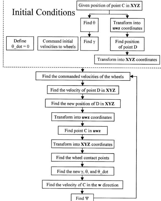
2.4.1 Simulation Program Structure
The simulation program structure is shown below. Refer to Appendix A for details.
r---Given position of point C in XYZ
Initial Conditions
Find 0 Transform into uwz coordinates Define Command initial Find y Find position
0 dot = 0 velocities to wheels of point D
Transform into XYZ coordinates
Find the commanded velocities of the wheels Find the velocity of point D in XYZ
Find the new position of D in XYZ
Transform into uwz coordinates
Find point C in uwz
Transform into XYZ coordinates
Find the wheel contact points
Find the new y, 0, and 9_dot
Find the velocity of C in the w direction
Find TP
2.4.2 Simulation Results
The figures shown below are for a 15 mm high bump with a peak value of fifteen. As the peak value is increased the bump becomes sharper. It is determined that this peak value offers a reasonably shaped bump. The length of the offset, s, is 35.875 mm, the length of the split, d, is 95 mm, the height from the SCMNM to the walker frame is 180 mm, and the diameter of the wheels is 76 mm. This bump is about five times as large as what may be found on a typical floor, but the larger bump more clearly exemplifies what can happen to the position of point D. The two lines traversing the floor are the wheel contact points. The single dashed line above the floor is the position of point D.
Position of Wheels and Point D Traversing the Floor
0.2 E0.15 N 0 0.05 0.4 0.4' 0.2 0.2 0
Position Y (i) -0.4 -0.4 Position X (m)
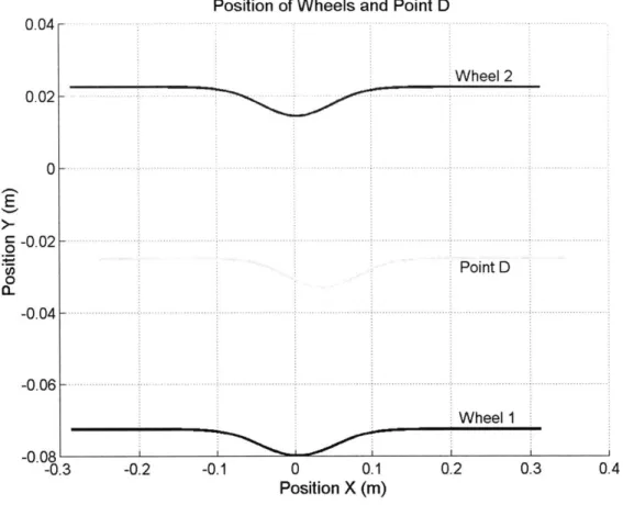
Position of Wheels and Point D 0.04 Wheel 2 0.02 0 -0.02-Point D 0 -0.04 -0.06 - -Wheel 1 -0.08 -0.3 -0.2 -0.1 0 0.1 0.2 0.3 0.4 Position X (m)
Figure 2-20: Top Down View of the Position of the Wheels and Point D
A top down view of the same path is shown in Figure 2-20 where the lower and upper lines indicate the paths of wheels one and two respectively, and the line in the middle indicates the path of point D.
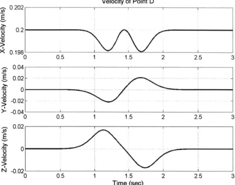
As one can see, the path of point D deviates from a straight line. However, the controller only dictates that the velocity of point D maintains a speed of 0.2 m/s in the X-direction and zero in the Y-X-direction; it cannot directly control the position of point D. Figure 2-21 shows the velocity of point D in all three directions. Note that the bump peaks at just under 1.5 seconds.
U, 0 x 0 0 0.202 0.2 Velocity of Point D 0. 198' 0 0.5 1 1.5 2 2.5 3 0.043 1 0.02 - -. -.--0.0 -0.04 0 0.5 1 1.5 2 2.5 3 0.02 1 1 1 0 -0.02 0 0.5 1 1.5 2 2.5 3 Time (sec)
Figure 2-21: Velocity of Point D
Lastly, Figure 2-22 shows the velocity of each of the wheels. Note that the bump causes the encoder shaft to rotate, which in turn causes the controller to modify the velocities of the wheels.
Velocity of Wheel 1 0 0.5 1 1.5 2 2.5 3 Velocity of Wheel 2 1 1 .5 Time (sec) 2 2.5 3
Figure 2-22: Velocity of Wheels One and Two
0.205 0 0.2 0.205- - -0 0.2 0 0.5 ______________________________________________________________________ L _________________________________
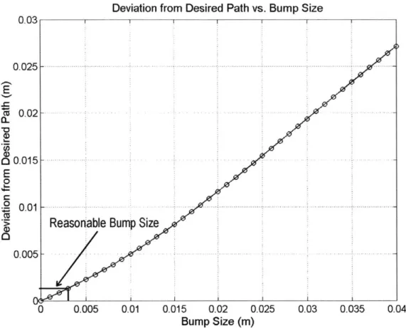
The deviation of point D from the desired path was found for bump sizes ranging from 0 to 40 mm with a peak of fifteen (no units) (see Figure 2-23). Measurements of a typical tiled floor indicate that a reasonable bump height is about 3 mm. The simulation was run for much higher values to show the non-linearity of the system. The results show that point D would only deviate from its intended path on the order of a few millimeters, which indicates that the control algorithms are sufficient for an uneven floor.
0.03
0. 025 F
015-0.01
Deviation from Desired Path vs. Bump Size
Reasonable Bump Size
.... -. ...-. 0.005 0.005 0.01 0.015 0.02 0.025 0.03 0.035 Bump Size (m) 0.04
Figure 2-23: Deviation vs. Bump Height
2.5 Conclusions
This chapter addresses the justification of the degree of freedom placed on the
SCMM. This chapter has two main points:
" The wheels of the omnidirectional platform with the added joint do indeed touch
the ground of an uneven floor.
* The control algorithms designed for a flat floor are valid for an uneven floor Thus, this chapter justifies design of the suspension joint on the SCMM.
0 0. E 0 0-0 0
Chapter
3
SmartWalker Stability
This chapter discusses designing the SmartWalker for stability. This includes design tools that ensure the SmartWalker will not slip, tipover, or experience brake failure. Current passive wheeled walkers on the market (see Figure 3-1) have several limitations that were avoided when designing the SmartWalker. Namely, these walkers have instabilities that cause them to either "run away" from the user or tip over.
Figure 3-1: Types of Wheeled Walkers on the Market (Walk Easy)
The standard wheeled walker configuration has two fixed wheels in the rear and two caster wheels in the front. Most often the two rear wheels have brakes that are activated by the user's hands, much like a bicycle brake. Some designs, which are inherently easy to tip over, have only three wheels. Furthermore, all of these types of walkers can run away from people if the user applies a forward force and subsequently does not move his feet. The following sections deal with the prevention of the above described walker instabilities.
3.1 SmartWalker Frame Configuration
The location of the SCMMs and passive casters of the omnidirectional platform is a critical design decision that has a direct impact on the stability of the SmartWalker. Implementing the omnidirectional mobility platform described in Chapter 2 is challenging because the user's stride can easily interfere with the platform. Configurations other than the one presented earlier were considered. Several reasonable configurations of the SmartWalker's frame and SCMM locations are shown in Figure
3-2. Configuration P space of SCMM A Inrterference
with gait
B
I.
o
Passive caster Split Caster Mobility Module C DFigure 3-2 Possible Frame Configurations for the SmartWalker
Each SCMM is free to rotate 360 degrees about the encoder shaft, which causes problems when designing the frame. This is shown in Figure 3-2A by displaying the SCMMs in two of their possible positions. The circles that surround the SCMMs represent the total space that the SCMMs can occupy. Care must be taken so that the configuration space of both the SCMMs and passive casters does not interfere with the user's gait. To avoid this, the SmartWalker's frame could have been made so large that
the SCMMs could not come close to hindering the user. However, if the SmartWalker is too large, then it will have problems moving through doors and other tight spaces. Thus, a balance must be made between a walker that is large enough to hold the SCMMs and also small enough to maintain a certain level of maneuverability. This is accomplished
by designing the SmartWalker to have the same footprint as a conventional passive
walker and a design close to configuration A. A three-wheeled walker (see Figure 3-2B,
D) is less stable, and putting the SCMMs in the rear (Figure 3-2B, C) would interfere
with the user's stride.
Given the walker wheel configuration, it must be shown that the walker is statically stable. There are three modes of instability in these walkers (Finkel, 1997).
1. The brakes hold, but the wheels slide.
2. The walker tips over.
3. The brakes fail.
3.2 Slipping
In the first case (see Figure 3-3), the user applies a force that results in a normal force on all four wheels and shear force on the braked wheels. Given the coefficient of friction, pt, the shear force of wheel i, Si, and the normal force of wheel i, Ni, if
2
y-si
> then the wheels will slip (Finkel, 1997).
4EN j=1 SF2\ F\ N2 2 N4 N1 S1 N3
For the SmartWalker, the front two wheels are replaced by the SCMMs, and the rear two wheels are passive casters. The SCMMs are simplified and represented as having a single contact point with the ground. The rear wheels are represented as spherical joints and thus only support normal forces. A free body diagram of the walker is shown in Figure 3-4. A three-dimensional analysis would show that the structure is statically indeterminate since there would be only six equations for eight unknowns, Fix,
Fiy, Frx, Fry, Ffrxl, Ffx2, Fby1, Fby2.
Fsin(D F Fcos(D mg d b Ffx2 Fi1 ixtFby2 F Ffy Fby
Iy
IFry
Side ViewFigure 3-4: Free Body Diagram of 2-D Walker
If it is assumed that the forces acting on the left and right side of the walker are equal,
then the forces on the side view of the SmartWalker can be calculated. In this case the following equations apply:
IF, = F cos$ + F, =0 (3-1)
SF, = -F sin 6 - mg + Ff + F, = 0 (3-2)
IM, = 2b(FY )-h(Fcosp)- j(F sin )- d(mg)= 0 (3-3)
The sum of the normal forces acting on the legs of the walker is:
4
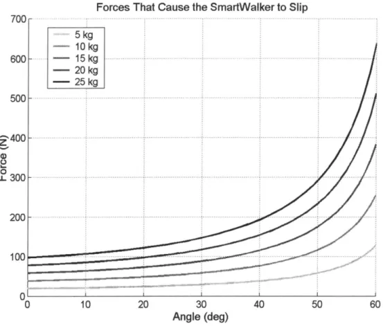
Figure 3-5 illustrates when the SmartWalker will slip. The different lines represent various masses of the SmartWalker. Any forces above the line will cause slip. As the angle at which the force is applied approaches ninety degrees, the force needed to cause slipping approaches infinity.
Forces That Cause the SmartWalker to Slip
700 - - 5 kg - 10kg 600 - 15 kg , ... , ... , ... ·· ... · .... · ..... :· ... ·· .... · .. · .... · ... ·,· ... · ... · .. 1: - 20 kg - 25 kg 500 ... , ... : ... , ... : ... : ... I Z400 ... . ; ... : ... , ....... .... ·: .. · ... · ...... · .............. ; ........ 1 '-'" Q) ~ ~300~ ... ·· .. · ... · .. ···,··· .. · ... ··· ... · .. :·· ... , ... : ... ~ 200~ ·· .... · ... · .... ···,· .. ···· .. ··· .... · ... : ... · .. ·· .. · ... , ... ~~ 100 ... , ... .
o
r=-o 10 20 30 Angle (deg) 40 50Figure 3-5: Forces That Cause the SmartWalker to Slip (Varying Masses)
60
This figure shows that although a light walker may be desirable in case it needs to be lifted off the ground, a certain mass does create a more stable walker. It can be assumed that the user would not be applying more than approximately 200 N (Godding, 1999). Even when the user is applying such a large load, it would mostly be in the Z
-direction, where <t> is close to ninety. In any case, a mass of approximately 15 kg is a good compromise between stability and lightness. At this weight, only extreme cases of high user applied force coupled with low values of <t> would cause the walker to slip.
3.3 Tip-Over
A simple two-dimensional analysis can show when the walker will tip over, but it
is not as accurate as a three-dimensional analysis. Instead, a more detailed stability measure is utilized (Papadopoulos, 1996). It takes into account the walker's mass and height of the center of mass and is applied to the entire walker, not just a 2-D representation of the walker. A brief description of the Papadopoulos stability margin is presented. A more detailed description can be found in Appendix B.
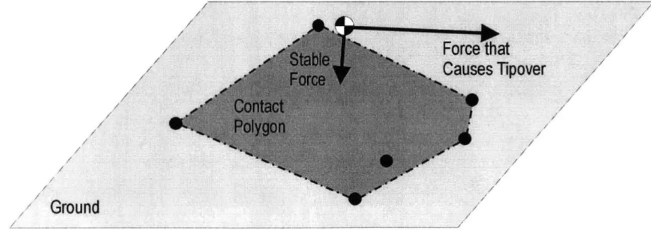
Tipover is described as when "a nominally upright vehicle body undergoes a rotation which results in a reduction of the number of ground contact points such that all remaining points lie on a single line (tipover axis)" (Papadopoulos, 1996). Only the outermost points, those that make up a convex polygon, are considered. This polygon is dubbed a "contact polygon," and is shown in Figure 3-6. Each of the black dots represents a point where a structure touches the ground. Note that one of the black dots lies within the convex polygon and thus does not constitute a vertex of the polygon. There are two different forces, each composed of the weight of the vehicle and any other external forces acting upon the body, that originate from the black and white circle. One of the forces lies within the polygon; the other lies outside of the polygon. The force that lies within the polygon will not cause the structure to tip over, while the other force will.
Force'that
Causes Tipover
Ground
A scalar stability measure, a, that is a function of the force described above and
the angle that the force makes with one of the edges of the contact polygon is described (Papadopoulos, 1996). Specifically,
a =
(Ei)nIfI
(3-5)where
E
is the angle between the force vector, fr, and the vector between the effective center of mass and the line that connects two vertices of the contact polygon. If a <0 then the walker is tipping over. If a > 0 then the walker is in a stable state.The key difficulty in applying this stability analysis to the walker is determining which wheels constitute a convex polygon. This arises because the split caster mobility modules (SCMMs) are constantly changing orientations. Figure 3-7 is a top-down view of the walker that shows the wheels with assigned numeric values.
1* 2 s a
0
Passive caster 6 5 4 3= Split Caster Mobility ModuleFigure 3-7: Numbering Diagram of the Omnidirectional Platform's wheels
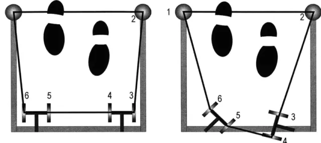
Wheels one and two remain fixed relative to the center of mass of the walker, while wheels three through six rotate as shown by the arrows. The center of mass of the person is assumed to lie either on or in front of the line connecting wheels one and two and thus does not contribute a vertex to the convex polygon. As the SCMMs rotate, different combinations of the wheels will form the convex polygon. This is shown in Figure 3-8. Note the configuration on the left uses wheels one, two, three, and six to form the polygon, while the configuration on the right uses wheels one, two, four, five, and six.
F
*
A&
A6
5 3
4 Figure 3-8 (a,b): Two Different Convex Contact Polygons
The algorithm to find which wheels to use works by finding the slopes of the lines from wheel two to wheel one, wheel three to wheel one, wheel four to wheel one, wheel five to wheel one, and wheel six to wheel one. It then finds the maximum value of those slopes. The maximum slope will determine which wheel is the next one to use. This procedure is then repeated for that wheel. After this is completed, the polygon's vertices are set and the procedure for determining the stability margin is given in Appendix B.
This analysis is used as a design tool to make certain that the chosen design is acceptable. Namely, the algorithm answers the question of whether or not the dimensions of the walker will result in a stable system when coupled with reasonable forces. An example of this is shown in Figure 3-9. The diagram shows the position of all six wheels as circles. The location of the encoder shafts are marked with a "+" sign. The center of mass is at the beginning of the "force vector due to mass." The force that is acting upon the force/ torque sensor is Fx = 10 N, Fy = 20 N, and F, = 80 N. The torque is
1, 2, and 0 Nm for Mx, My, and M, respectively. The dimensions correspond to the
SmartWalker's measurements. Note that Fr resides inside the contact polygon, which along with a tipover measure of thirty-one, indicates that the walker is stable and will not tip over.
Tipover Analysis 1 0.5 0 0 (-r ~ -1 Y-F
Force Vector Acting
Convex Polygon
on F/T Sensor
Force Vectbr,
Due to Mass.
F
Wheel Location.
0.20.1
Encoder Shaft
0
.ocation
osition (m) 0Location
0 0.1 -0.2 X-Position (m)Figure 3-9: Tipover Analysis
3.4 Brake Failure
The SmartWalker does not have any user-applied brakes, but the motors can serve as brakes if they are powered and commanded not to move. Thus, "brake" failure for the SmartWalker will only occur if the torque applied to the motors is greater than the motor stall torque. A free body diagram of the case when all four of the SmartWalker's wheels are facing parallel to the user-applied force is shown below.
0
F / f4 / / / 'ii ii 1/ f r
Figure 3-10: Free Body Diagram for Braking The sum of the forces is:
F= f
fn r r
where:
and
where p is the gear ratio. The total torque is:
r = -stai* P force that is
(3-8) needed to overcome the motor stall
(3-9)
where n is the number of motors. For the chosen design the result is:
4230 -28
( 39 (3-10)
= 660 N
This is an exceptional force, and is unlikely to be applied to the SmartWalker.
3.5 Conclusions
The analyses done in this chapter show that the SmartWalker's frame design, footprint, and motor choices are all suitable to prevent the SmartWalker from losing its
stability, either through slipping, tipping over, or brake failure.
(3-6)
(3-7)
F = n
Chapter
4
Mechanical Design
The focus of this chapter is the detailed mechanical design of the SmartWalker. The chapter includes the justifications of the design decisions regarding the wheels, the housing that holds the motors, gears, and wheels together, the slip rings, the bearings, the axles, the encoder shaft, the motors, and the frame. A photograph of the final product is shown below. It shows the SCMMs, the camera for the vision system, the acoustic sensors, and the computer housing.
Vision System
Sonar Array
Handle Bars
Computer Housing