Design and Analysis of High-Speed Continuous
Micro-Contact Printing
By
SMASSACHUSTTS
-. ,
INSTITUTEO-Xiao Shen
D
EC
0
2008
M.Eng. in Manufacturing
LIBRARIES
Massachusetts Institute of Technology, 2008
Submitted to the Department of Mechanical Engineering in Partial
Fulfillment of the Requirements for the Degree of
Master of Engineering in Manufacturing
At the
Massachusetts Institute of Technology
September, 2008
Copyright 2008 Massachusetts Institute of Technology, all rights reserved.
Signature of
Author:
Xiao Shen
Department of Mechanical Engineering
August 21, 2008
Certified by:
David E. Hardt
Professor, Mechanical Engineering
Thesis Supervisor
Accepted by:
Lallit Anand
Chairman, Departmental Committee on Graduate Studies
Department of Mechanical Engineering
Design and Analysis of High-Speed Continuous
Micro-Contact Printing
By
Xiao Shen
Submitted to the Department of Mechanical Engineering on Aug. 21h 2008 in Partial
Fulfillment of the Requirements for the Degree of
Master of Engineering in Manufacturing
Abstract
Micro-contact printing ( tCP) is a technology that prints directly off a patterned elastomeric stamp
by transferring only a molecular monolayer of ink to a surface, providing a low-cost,
high-resolution and widely applicable method of nano-scale patterning. Roll to roll is recognized as
one of the most promising models for high volume micro-contact printing since it offers
advantages such as high throughput, convenient material handling and conformal contact
propagation. We have designed and built a tool to study the behavior of micro-contact printing in
a roll to roll paradigm, with the three fold objective of printing at high speeds, over large areas
and obtaining good quality. A speed of as high as 400 feet/min was achieved with good printing
quality. This thesis provides details of this roll to roll high speed micro-contact printing technique
from mechanical design to system control to final experiment result analysis, with a concentration
in system control. We were also able to keep the distortions to as low as 28 microns over an area
of 5.8"x5" and maintain dimensional distribution within 1 micron. A proof-of-concept continuous
etching tool was also built to match the speed of the print tool.
Table of Contents
A bstract ...
3
Table of C ontents
...
4
A cknow ledgem ents ...
...
7
List of Figures ...
9
List of Tables... ...
12
1
O verview of the Thesis ...
13
1.1
Introduction ...
13
1.2
O bjectives ...
14
1.3
A pproach ...
15
1.4
Scope ...
15
1.5
Task D ivision... 16
2
Scientific and Engineering Foundation ...
17
2.1
Soft Lithography ... 17
2.1.1
Introduction ... 17
2.1.2
Soft Lithography Taxonomy ...
18
2.1.3
Micro-contact Printing...20
3
Traditional Printing Techniques ... 29
3.1
G ravure and Flexography ... 29
3.1.1
Prepress, Flexography ... 29
3.1.2
Prepress, G ravure ... ... 30
3.1.3
Press ...
31
3.2
Comparison between Micro-contact Printing and Traditional Printing Techniques
34
3.2.1
Prepress ... 34
3.2.2
Press ...
34
4
Machine Design and Realization ...
37
4.1
Print M achine ...
37
4.1.1
Print M odule ... ... 39
4.1.2
Supply M odule ...
41
4.1.3
Collect M odule ... ... 42
5
Control System Design and Realization ...
47
5.1
Control System Overview ... ... 47
5.2
Control Program and Logic Flow ...
. ...
48
5.3
PID Control M ethod Overview ...
50
5.4
Feed-Back Tension Control System Design ...
... 51
5.4.1
W eb Tension Control ... ... 51
5.4.2
Unwind Tension Control...
53
5.4.3
Printing Tension Control ...
54
5.4.4
Rewind Tension Control ... ... 56
5.5
PID Tuning and Effect ...
56
5.6
Tuning Process and Result ... ... 57
5.6.1
Ziegler-Nichols M ethod ...
57
5.6.2
Tuning Kp ... ... 58
5.6.3
Tuning KI ...
61
5.6.4
Tuning KD... 64
5.6.5
Periodicity of Signals ... 67
5.7
Tension Control Result Analysis ...
71
6
Experim ental M ethods ... 75
6.1
High-Level Process M odel ... 75
6.2
M easurement M ethods ...
77
6.2.1
Print Yield ... 77
6.2.2
Dimension...
77
6.2.3
Distortions ... 78
6.3
Design of Experiments ... 79
7
Results and Analysis... 81
7.1
Control Performance... 81
7.2
Results from Designed Experiments ...
84
7.3
One Dimensional Speed Scan ...
86
7.4
Air Trapping ... 87
7.5
Stamp Durability ...
89
7.6
Continuous Etching M achine ...
89
8
Conclusion ...
91
10
Reference ...
94
A ppendix A ...
96
Acknowledgements
Firstly, I would like to thank my teammates: Adam Stagnaro and Kanika Khanna. Throughout the project, we worked together as a team, facing challenges, solving problems, making improvements, sharing happiness, and finally finishing the project within limited time and resources. They are not only good friends but also good teachers who I have learned a lot from.
I want to thank my thesis advisor Professor David Hardt who was with us whenever we needed and always giving insightful ideas. He also devoted tremendous amount of time into the coordination of the thesis project which enabled us to concentrate on the research. Without him the project would not have happened in the first place and would not have achieved the result as it is today.
I also thank Nano-terra for providing us with a very friendly and supportive working atmosphere. I appreciate the enormous amount of trust and support they provided with us throughout the project. Especially, I would like to thank Karan Chauhan (Engineer Nano-terra), who was mentoring us in the whole project. He did all he can from advising us on detailed technique problems to serving as the liaison between us, Nano-terra and MIT, helping us achieve a good project and making sure we all have learned from the project.
List of Figures
Figure 1-1 A schematic of the roll to roll micro-contact printing process ... 15
Table 2-1 Comparison between photolithography and soft lithography [1]... 18
Figure 2-1(a) Diagram of process (b) Scanning electron microscopy (SEM) micrographs of the master, (c) image of the stamp, and (d) SEM micrograph of a printed and etched pattern ... 19
Figure 2-2 Metallic multilayer pattern made by using the self assembly of polystyrene spheres as regular m asks tem plates [9] ... ... 21
Figure 2-3 Schematic representation of a self-assembled monolayer (SAM) e.g. consisting of densely packed alkanethiolate molecules bound to a gold (AU) surface [9]... 22
Figure 2-4 a-b I Photoresist is spin-coated on a silicon wafer. c I A mask is placed in contact with the layer of photoresist. d
I
The photoresist is illuminated with ultraviolet (UV) light through the mask. An organic solvent dissolves and removes photoresist that is not crosslinked. The master consists of a silicon wafer with features of photoresist in bas-relief. An expanded view of one of the microfabricated structures with its characteristic critical dimensions is shown. e ( PDMS is poured on the master, cured thermally and peeled away. fI
The resulting layer of PDMS has microstructures embossed in its surface. PDMS, poly(dimethylsiloxane) ... 23Figure 2-5 Conformal contact between a stamp and a hard substrate. (a)Stamp composed of a patterned elastomer and a flexible backplane adapts its protruding zones to (b) the macroscopically uneven substrate and (b, inset) its microscopic roughness, whereas recessed zones do not touch the substrate. (c) Dependence of maximal roughness amplitude for spontaneous formation of conformal contact on a substrate with sinusoidal roughness of wavelength () for a stamp with a Young's modulus of 2.5 MPa and a work of adhesion of 0.1 J/m2 (Sylgard 184, solid curve) and for a stamp with a modulus of 9 MPa and a work of adhesion of 0.03 J/m 2 (dotted curve) [2] ... 25
Figure 2-6 Comparison of surface diffusion effect comparison among different inks... 26
(DDT: dodecanethiol, HDT: hexadecanethiol, ECT: eicosanethiol) [2] ... 26
Figure 2-7 Contact Inking (a) and Immersion Inking (b) [2] ... ... 26
Figure 2-8 Pattern fidelity (defects and pattern width) as a function of ink (ECT) concentration [2] ... 27
Figure 2-9 Pattern fidelity (defects and pattern width) as a function of contact time [2]... 28
Figure 3-1 Close-up of flexography stamp [3] ... 30
Figure 3-2 Gravure stamp cells [16] ... 31
Figure 3-3: Typical setups for flexography (left) and gravure (right) ... 33
Table 3-1 Comparison of the three printing techniques: Gravure, Flexography and Micro-contact Printing ... ... ... 36
Figure 4-1 Three Modules that compose the print machine ... ... 38
Figure 4-2 3D view of the print machine ... ... 39
Figure 4-3 An exploded view of the Printing Module... ... ... 40
Figure 4-4 An exploded View of the supply module ... ... 42
Figure 4-5 An exploded view of the Collect Module ... ... 43
Figure 4-6 A 3D view of the Etching Module... ... 45
Figure 4-7 A schematic of the module combination. Additional processing steps can be added by attaching m ore m odules... 45
Figure 4-8 A design spreadsheet used to calculate the number of roller... 46
Figure 5-1 DirectLogic06 PLC [20] ... ... 48
Figure 5-2 Logic flow-chart of the PLC program ... ... 49
Figure 5-3 Block diagram of PID controller ... 51
Figure 5-4 System and Tension Zones ... ... 52
Figure 5-5 Tension Decomposition in Unwind Tension Zone ... ... 54
Figure 5-6 Diagram of Printing Tension Control ... 55
Figure 5-7 Tension in Printing Tension Zone ... ... ... 55
Figure 5-8 Tension Measurement on Tension Sensor 1 ... ... 56
Figure 5-9 PID View Function in Diresoft 5 ladder logic programming software... 57
Upper chart: blue line: Set point, Green Line: tension value; ... ... 57
Table 5-1: Parameter Setting Using Ziegler-Nichols method [19] ... 58
Figure 5-10 PID Tuning Effect: Kp = 1, KI=0, KD = 0... ... 59
Figure 5-11PID Tuning Effect: Kp = 5, KI=0, KD = 0... ... 59
Figure 5-12 PID Tuning Effect: Kp = 10, KI=0, KD = 0... ... 59
Figure 5-13 PID Tuning Effect: Kp = 20, KI=0, KD = 0... ... 60
Figure 5-14 PID Tuning Effect: Kp = 50, KI=0, KD = 0... ... 60
Figure 5-15 PID Tuning Effect: Kp = 3, TI=4, KD = 0 ... ... 61
Figure 5-16 PID Tuning Effect: Kp = 3, TI=2, KD = 0 ... ... 62
Figure 5-17 PID Tuning Effect: Kp = 3, TI=1, KD = 0 ... ... 62
Figure 5-18 PID Tuning Effect: Kp = 3, TI=0.6, KD = 0 ... ... 62
Figure 5-19 PID Tuning Effect: Kp = 3, TI=0.3, KD = 0 ... ... 63
Figure 5-20 PID Tuning Effect: Kp = 3, TI=0.1, KD = 0 ... ... 63
Figure 5-21 PID Tuning Effect: Kp = 3, TI=0.6, KD = 0.02 ... ... 64
Figure 5-22 PID Tuning Effect: Kp = 3, TI=0.6, KD = 0.05 ... ... 64
Figure 5-23 PID Tuning Effect: Kp = 3, TI=0.6, KD = 0.1 ... ... 65
Figure 5-24 PID Tuning Effect: Kp = 3, TI=0.6, KD = 0.25 ... ... 65
Figure 5-25 PID Tuning Effect: Kp = 3, TI=0.6, KD = 0.5 ... ... 66
Figure 5-26 Run data without feed-back control- showing Periodicity of load and tension signal68 Figure 5-27 Overlay of 15 runs of load data ... 69
Figure 5-28 An exploded view of the Stamp Roller Assembly... ... 70
Figure 5-29 A section view of the stamp-roller interface... ... 71
Figure 5-30: Effect load Extraction (blue: tension, green: upper-threshold, red: lower-threshold, blue bar: stam p area (blue) ... ... 72
Figure 5-31 Extracted Effective Tension( the tension during the real print)... 73
Figure 5-32 Histogram of Tension on Stamp ... 74
Figure 5-33Typical tension profile in one run... 74
Figure 6-1 Process Model for Roll-to-Roll Microcontact Printing ... 75
Figure 6-2 Critical pixel dimensions (Green area is etched) ... 78
Figure 6-3 Typical Distortions Vector Map ... ... ... 79
Figure 6-4 The 23 full factorial design of printing load and speed ... 80
Figure 7-1 Typical Profile of Tension and Load under PID Control (30 ftm) ... 81
Figure 7-2 Typical Profile of Tension and Load under PID Control (60 ftm) ... 82
Figure 7-4 Typical Profile of Tension and Load under PID Control (240 ftm) ... 83
Figure 7-5 Typical Profile of Tension and Load under PID Control (400 ftm) ... 83
Table 7-1 Tension Statistics at different speeds ... 83
Figure 7-6 95 percent confidence intervals on the average pixel lengths as a function of printing
speed... 86
Figure 7-7 Typical air trapping(under 50X microscope)... ... 87
Figure 7-8 Systematic air trapping pattern ... 88
Figure 7-9 Air trapping becomes apparent above 240 fpm, Photographs have been taken from corresponding areas in each print ... 88 Figure 7-10Comaprison of stamp situation at first print and last print... . 89 Figure 7-11 Photo of continuous etching machine ... 90
List of Tables
Table 2-1 Comparison between photolithography and soft lithography [1]... 18
Table 3-1 Comparison of the three printing techniques: Gravure, Flexography and Micro-contact
Printing ...
... 36
Table 5-1: Parameter Setting Using Ziegler-Nichols method [19] ...
. 58
Table 7-1 Tension Statistics at different speeds ...
...
83
Table 7-2: Consolidated Results for Distortions and Dimensions from 3 x 2 Set of Experiments [8]
...
...
...
84
Table 7-3: Analysis of Variance for Average Pixel Length for 3 x 2 Set of Experiments [8] ... 85
Table 7-4: Analysis of Variance for Average Pixel Width for 3 x 2 Set of Experiments ... 85
Table 7-5: Analysis of Variance for 95 percentile Distortions for 3 x 2 Set of Experiments [8].. 85
1 Overview of the Thesis
1.1 Introduction
Micro-fabrication is one of the most important areas that enables today's achievement of
information technology. It is ubiquitous in the fabrication of sensors, micro-reactors,
combinatorial arrays, micro-electromechanical systems (MEMS), micro-analytical systems, and
micro-optical systems 10. The current dominant micro-fabrication technology is photolithography,
which is essentially used to fabricate all integrated circuits. However, photolithography suffer
from some limitations such as high-cost, can only apply to planar surfaces, and directly applicable
only to a limited set of photosensitive materials [2].
Micro-contact printing (jICP), a recent technology that prints directly off a patterned elastomeric
stamp by transferring only a molecular monolayer of ink to a surface, gives rise to an alternative
method of low-cost, large area, high-resolution and widely applicable method of
micro-fabrication [2]. It has been demonstrated with a resolution of 30nm and a minimum feature size of
40nm with millisecond deposition times.
Promising as Micro-contact printing is, its production is still at lab-scale level. High throughput,
high resolution manufacturing methods need to be explored to enable the high volume
manufacturing and achieve the scale economy.
Traditional roll to roll flexography printing has long been proven to be a robust, high throughput
technique of printing. It also has the advantage of being able to print on a wide variety of
substrates [3]. It has been successfully used in printing RFID tags at large volume, as well as
printed batteries, organic circuits, photovoltaics and low-cost lighting [4]. The highest resolution
possible in flexography today is approximately 20pm, but it has achieved higher resolutions in trials in the printed electronics area [5].
In light of the success of roll to roll flexography printing in these areas, we applied it to our project to combine it with the gCP. Results shown that the design is promising. We were able to achieve good printing quality and small distortion at high throughput and the process is robust and highly repeatable.
The thesis is organized as follows: the rest of the first chapter describes the objectives, approach and scope of this project as well as the task division in this project. The second chapter gives an extensive literature review of the traditional printing method and pCP. In Chapter 3, the design
detail of the printing tools used in this project is discussed. Control system design and
optimization as well as control algorithm are discussed in Chapter 4. Chapter 5 explains about the
design of experiments. Experiment results and analysis are further studied in Chapter 6. Chapter 7 gives a conclusion to the project. Future works are discussed in Chapter 8.
1.2 Objectives
The objective of this project is to develop knowledge about roll to roll continuous gCP. Specifically, we are going to develop tools and techniques for which can achieve: high quality, over a large area and at a high speed (>100 feet/min).
As the main part of the project, a pCP machine was built to demonstrate high speed continuous micro-contact printing; a continuous etching machine was also built that can etch the substrates processed by the printing machine. Both machines are completely automatic from substrate
supply to final substrate collecting. A set of stamp making tools were also used to supply high quality- large scale PDMS stamps used on the printing machine.
1.3 Approach
We used the combination of roll to roll flexography printing method and tCP techniques as the
major mechanical design concept; apply active feed-back control on web motion and tension;
adopt design of experiments (DOE) techniques to optimize the process parameters and minimize
noise disturbance so as to achieve the aim of high quality, large print area and high speed pCP. Figure 1-1 shows a schematic of the roll to roll micro-contact printing process.
Z Z z z z co . SUPPLY Z , COLLECT SUPPLY _ ni I: IIIIIN4
Figure 1-1 A schematic of the roll to roll micro-contact printing process
1.4 Scope
The scope of our project is limited to pCP on gold substrates using Hexadecane Thiol [6]. Since
the focus of this project is to demonstrate the possibility of high-speed, high-volume production
using the micro-contact printing technology. The limitation to gold substrate and Hexadecane
1.5 Task Division
This project is mainly divided into three parts with each team member be responsible for one part but also participated by other members. Adam Stagnaro is responsible for mechanical design (printing and etching machine) [7], Kanika Khanna is responsible for experiment design and analysis [8]. I am responsible for Electronic and Control Systems Design as well as PLC programming. We did all the machine assembly and experiments as a team.
2 Scientific and Engineering Foundation
2.1 Soft Lithography
2.1.1
Introduction
Soft lithography is a set of micro-fabrication methods that can form nano-scale pattern by using a
patterned elastomeric as the stamp to form a contact on the molecular scale between the stamp
and substrates [1].
In the area of micro-fabrication, photolithography is always the dominant technology. However,
it also suffers from some drawbacks. For example, it has a relatively high cost; it is not suited for
patterning non-planar surfaces; it provides almost no control over the chemistry of the surface and
hence is not very flexible in generating patterns of specific chemical functionalities on surfaces
(e.g. for anchorage-dependent tissue culture or combinatorial chemistry); it can generate only
two-dimensional microstructures; and it is directly applicable only to a limited set of
photosensitive materials (e.g. photoresists) [1]. The characteristics of photolithography are such
that it is relatively little used for micro-fabrication based on materials other than photoresists; to
work with other materials it is necessary to attach chromophores or add photosensitizers, and
neither type of procedure is convenient. Thus, the technique of soft lithography which can be
used to produce pattern with dimensions as low as 30 nm, provides an alternative,
non-photolithographic set of micro-fabrication methods which generates micropatterns and
microstructures at low cost and with wide range of application from [1].
Definition of patterns
Materials that can be
patterned directly
Surfaces and
structures that can
be patterned
Current limits to
resolution
Minimum fearure
size
Rigid photomask(patterned
Elastomeric stamp or mold(a
Cr supported on a quartz
PDMS block patterned with
plate)
relief features
Photoresists(polymers with
photo-sensitive additives)
SAMs on Au and SiO2
Planar surfaces
2-D
structures
-250
nm(projection)
-100
nm(laboratory)
-100nm
(?)
Photoresistsa
,eSAMs on Au, Ag, Cu, GaAs,
Al,
Pd, and
SiO2aUnsensitized polymers(epoxy,
PU, PMMA, ABS, CA, PS,
PE, PVC)b-e
Precursor polymers(to
carbons and ceramics)cd
Polymer beadsd
Conducting polymersd
Colloidal materialsa,d
Sol-gel materialsc d
Organic and inorganic saltsd
Biological macromoleculesd
Both planar and nonplanar
Both 2-D and 3-D structures
-30nmab, -60nme, -1 pmd' e
(laboratory)
10(?) - 100nm
a-c Made by (a)pCP. (b) REM. (c) pTM. (d) MIMIC. (e) SAMIM. PU: polyurethane; PMMA: poly(methyl methacrylate); ABS; poly(acrylonitrile-butadiene-styrene); CA; cellulose acetate;
PS: polystyrene; PE: polyethylene; and PVC: poly(vinyl chloride)
2.1.2
Soft Lithography Taxonomy
As a family of related patterning approaches, soft lithography is mainly composed of several
similar techniques including: micro-contact printing (pCP), replica molding (REM),
microtransfer molding (pTM), micromolding in capillaries (MIMIC), solvent-assisted
These techniques share some common features: i) They all use a patterned elastomer as stamp which is made using a silicon master. ii) The master is usually fabricated using high-resolution
techniques such as photolithography or e-beam. Figure 2-lillustrated the components of the
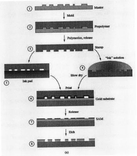
Soft-lithography. Figure 2-1 (a) is a diagram of process: A prepolymer (2) covering the master (1) is cured by heat or light, and demolded to form an elastomeric stamp (3). The stamp is inked by
immersion (4) or contacted with an ink pad (5), and printed onto the substrate (6), forming a
self-assembled monolayer (SAM). The ink pattern (7) is then transferred into the substrate by a
selective etch (8). Figure 2-1 (b) is the scanning electron microscopy (SEM) micrographs of the
master, Figure 2-1 (c) is the image of the stamp, and Figure 2-1 (d) is a SEM micrograph of a printed and etched pattern.
(a)
Figure 2-1(a) Diagram of process (b) Scanning electron microscopy (SEM) micrographs of the
In the rest of the thesis, we exclusively focus on one of the soft lithography family- the micro-contact printing (gCP) technique [2].
2.1.3 Micro-contact Printing
Micro-contact printing (pCP) is one technique of the soft lithography family. It uses the relief pattern on the surface of a PDMS stamp to form patterns of self-assembled monolayers (SAMs) on the surfaces of substrates by contact. Microcontact printing differs from other printing methods in the use of self-assembly (especially, the use of SAMs) to form micropatterns and microstructures of various materials [1].
In this section, different aspect of the micro-contact printing technique is discussed, from the process to the application to the essential characteristics of lCP. Limitations and potential
applications are also discussed.
2.1.3.1 Principle of Self-Assembled Monolayers (SAM)
Self-assembly is the spontaneous aggregation and organization of subunits (molecules or micro-scale objects) into a stable, well defined structure via non-covalent interactions. The information that guides the assembly is coded in the properties (e.g. topologies, shapes, and surface functionalities) of the subunits; the individual subunits will reach the final structure simply by equilibrating to the lowest energy form. Because the final self-assembled structures are close to or at thermodynamic equilibrium, they tend to form spontaneously and to reject defects. Thus assembly provides a simple route to certain types of structures. A variety of strategies of self-assembly has been developed and employed to fabricate two- and three-dimensional structures with dimensions ranging from molecular, through microscopic, to macroscopic sizes [1]. Figure 2-2 shows a unique multilayer landscape made by micro-contact printing. The use the self
assembly of polystyrene spheres enables the formation of highly regular templates that can then be used as masks to deposit metallic multilayer systems [9].
Figure 2-2 Metallic multilayer pattern made by using the self assembly of polystyrene spheres as regular masks templates [9]
It is the use of SAM that making micro-contact printing different from other printing methods. SAM also contributes to the many special features of tCP such as high resolution, complete coverage as an etching mask and low ink transfer time[ ][1 1].
Although these monolayers do only have a thickness corresponding to the length of just one ink molecule, which typically has a longer axis of about 2-3 nm, they are very stable and resistant against chemical and physical stresses during processing. This makes them ideal as etch resists in a photo-mask-free process. Figure 2-3 shows alkanethiolate molecules self assemble as a
Figure 2-3 Schematic representation of a self-assembled monolayer (SAM) e.g. consisting of densely packed alkanethiolate molecules bound to a gold (AU) surface [9]
2.1.3.2 Stamp Fabrication
The stamp is usually made from an elastomeric polymer, such as poly (dimethylsiloxane) (PDMS). This material allows for conformal contact (will be further discussed in next section) with the substrate combined with advantageous chemical and physical properties important for the ink transfer behavior [12].
Stamps are fabricated by casting a pre-polymer on a master with a negative of the desired pattern. A schematic of the fabrication method is shown in Figure 2-4. First, a Master is fabricated using proven high resolution techniques, such as photolithography, e-beam, or micro-machining. (However, a Master could also be an existing structure that does not require processing like a human hair or some woven fabric.) Then an elastomer, such as polyurethane or a silicone is poured onto the Master, hardened using heat or ultraviolet light, and peeled off to yield a mold.
The resulting mold is the exact structural inverse of the original master - down to nanometer
accuracy depending on the combination of materials used and the precision of the replication process
Deposit
AAA ~ ,rne -500
nm
-500
Urn
dissove photoresist
,wPour on PDMS:
cure (65"C peel away PDMS
."
f
Ernbosed microstructures
Natui Reviews
j
McrobioogyFigure 2-4 a-b I Photoresist is spin-coated on a silicon wafer. c I A mask is placed in contact with the layer of photoresist. d
I
The photoresist is illuminated with ultraviolet (UV) light through the mask. An organic solvent dissolves and removes photoresist that is not crosslinked. The master consists of asilicon wafer with features of photoresist in bas-relief. An expanded view of one of the microfabricated structures with its characteristic critical dimensions is shown. e I PDMS is poured on
the master, cured thermally and peeled away. f I The resulting layer of PDMS has microstructures embossed in its surface. PDMS, poly(dimethylsiloxane).
3iIICoto wa.. ...
2.1.3.3 Conformal Contact
A printing process, no matter how advanced as it is, is composed of two steps. The first is to define an accurate pattern, and the second is to bring close enough that pattern and the substrate to be printed on so that the desire physical or chemical process, such as ink transfer and chemical reaction can happen.
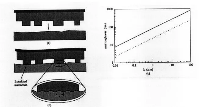
The conformal contact printing in high-resolution printing goes beyond the traditional definition of the contact between the asperities of two flat, hard surfaces. From a macroscopic view, it's the adaption to the overall shape of the substrate; from a microscopic view, it's the adaption of a soft polymer layer to a rough surface. This combination leads to an intimate seamless contact. The formation of this seamless adaption should be partially attributed to the adhesion forces. Even without the application of external pressure, an elastomer can automatically compensate for some degree of substrate roughness, depending on the materials properties. Figure 2-5 shows how a stamp can compensate for surface roughness.
The stamp we used is composed of a patterned elastomeric (blue layer in Figure 2-5 ) attached to
a layer of stainless steel with a thickness of 0.005" inch (dark layer in Figure 2-5). In this stamp, the conformal prosperities of the stainless steel metal and those of the elastomer part are complementary. This combination provides us compensation ability in a wide range (from 1 gim to above 100pm). The elastomer compensates for local surface roughness amplitudes of up to 1 pm (Figure 2-5 (c)), whereas long-range warp (wavelengths greater than 100pm) is compensated by the flexibility of the backplane (Figure 2-5 (b)) [2].
Ii
A.
S
I
a
Figure 2-5 Conformal contact between a stamp and a hard substrate. (a)Stamp composed of a patterned elastomer and a flexible backplane adapts its protruding zones to (b) the macroscopically
uneven substrate and (b, inset) its microscopic roughness, whereas recessed zones do not touch the substrate. (c) Dependence of maximal roughness amplitude for spontaneous formation of conformal
contact on a substrate with sinusoidal roughness of wavelength
0
for a stamp with a Young's modulus of 2.5 MPa and a work of adhesion of 0.1 J/m2 (Sylgard 184, solid curve) and for a stampwith a modulus of 9 MPa and a work of adhesion of 0.03 J/m2 (dotted curve) [2].
2.1.3.4 Ink Type, Inking Method and Concentration Selection
As mentioned in the previous section. The adoption of alkanethiols as ink, which can form a dense and ordered layer on noble-mental surfaces such as Au and Ag is one of the most important characteristic of micro-contact printing. It is also found that the accurate reproduction of small patterns can be compromised by the diffusion of ink molecules away from the zones of contact. The formation of a defect-free resist requires time and enough reactants to form a monolayer, but this also provides an opportunity for the thiol molecules to diffuse.[2]
In fact, the width of the diffusion zone scaled with the mobility of the molecules: Use of linear
alkanethiols with molecular weight increasing from 158 g mol-' (dodecanethiol, DDT) to 258 g
mo'l- (hexadecanethiol, HDT), and up to 314 g molP (eicosanethiol, ECT) decreased both the
-vapor-phase transport and the surface diffusion of the ink during printing. ECT allows the surface
____
01 o1 10 100 WC)
diffusion zone to be reduced to values of less than 100 nm for immersion inking of the stamp and to values of less than 50 nm for contact inking of the stamp. As shown in Figure 2-6 ECT offered the best compromise between limited diffusion during printing and good protection of the gold against the cyanide/02 etch [2].
DDT HDT ECT
Figure 2-6 Comparison of surface diffusion effect comparison among different inks (DDT: dodecanethiol, HDT: hexadecanethiol, ECT: eicosanethiol) [2]
Two common methods of inking a stamp are immersion inking and contact inking. Immersion inking (Figure 2-7 (b)) is done by placing ink solution (red) onto a stamp (blue) for a while (about 30 seconds) and then dry by blowing nitrogen. This method allows the control of average amount ink transferred.
Contact inking (Figure 2-7 (a)) is done by contacting stamp with a PDMS (lower part) ink pad pre-impregnated with inking solution. This method helps direct the ink onto the stamp. By using contact printing, the completeness of the print becomes less sensitive to geometry of the pattern, more important, the diffusion of the thiols is minimized.
- - -
-a
Figure 2-7 Contact Inking (a) and Immersion Inking (b) [2]
Control over the amount of ink transferred was possible by changing the concentration of the ink solution used for preparing the ink pad. Figure shows how both the number of defects and the apparent width of the etched pattern depended on the ink concentration. In this example, best accuracy (ink diffusion less than 2 X 40 nm) and lowest defect counts (2%) were achieved for a 0.1 -mM solution of ECT.
I
0.01
0.1
Concentration of ECT (mM)1000
700 I5Figure 2-8 Pattern fidelity (defects and pattern width) as a function of ink (ECT) concentration [21
2.1.3.5 Contact Time
The contact time is the amount of time that stamp and substrate is contacted together. It is found that the less the contact time, the less the ink diffusion, however, the higher possibility the incompleteness in large features appear. So there needs an optimization process when the pattern to be printed contains both small features, which need to be printed with high accuracy, and large features, which needs low defects. It has been proved that contact time as less as Ims is possible for micro-contact printing [11] although typical contact time is in seconds. In Figure 2-9 the effect of different contact time is shown.
4l -I ---.ii I' : : : ~ r~~r rr. tsrl-r~rrrrrrr lr r ,rir
i
i
"4~~ ~ j i j I : : : :::--- ---
--r--- -,~
r -r
-r
r- r
: ~: ~ : : ?~I
---
---
--;--- --;--
r)u~ ~;-;l
T-
: : ; ::13 ~iii
I . . IYYL
... :i~1000 90W
8000
oo
~I
6oo 00z 500 : : : ; : i i i i i...
!, ...
...
....
!...
....
..
,.
-i!
}
..
i .. 144i i i ii U j I 1 1131db IV~
Y~: llflPrining time for ECT at 0.1 mM (S)
Figure 2-9 Pattern fidelity (defects and pattern width) as a function of contact time [2]
_-' j
3 Traditional Printing Techniques
This chapter reviews the two of the most used traditional printing techniques: Gravure and
Flexography. A comparison between these techniques and pCP is then presented.
3.1 Gravure and Flexography
Gravure and flexography are two of the most common methods of large-scale printing used today.
They are very similar in method, but differ mainly in the type of stamp, applications, setup costs,
and quality.
Flexography is commonly used to print corrugated containers, folding cartons, sacks, plastic bags,
milk and beverage cartons, disposable cups and containers, labels, adhesive tapes, envelopes,
newspapers, and various applications in electronics. The process uses a stamp with raised
surfaces to print on the substrate.
Gravure is typically used on packaging, labels, electronics (RFID tags, sensors, etc.), and
magazines. This is the preferred method for printing on flat materials. The stamp used in gravure
is a negative of the print pattern and consists of many tiny cells. Gravure is typically more
repeatable than flexography and more suited for long production runs due to higher setup costs.
Both can be divided into three sub-processes: prepress, press, and postpress.
3.1.1
Prepress, Flexography
The prepress step involves the manufacture of the stamp. Typical materials for flexography
include rubber and photopolymers. Stamps can be made via laser etching and photolithography.
Minimum feature size is on the order of
50-75
pm with registration repeatability of around 200
pm or better. Costs vary considerably depending on size, complexity of the pattern, and process used. Typically costs are approximately $100-150 for a 16"x 18" plate of average complexity plus other costs such as backing materials, mounting materials, and labor for installation of the stamp onto the machine [14].
Figure 3-1 Close-up of flexography stamp [3]
Typical waste outputs in flexography during plate manufacture include: Film, paper, developer, fixer, cleaning solutions, scrap plates and materials, plate-processing solvent, and water [15].
3.1.2 Prepress, Gravure
Stamps for gravure are typically made of copper. The features are comprised of a series of cells made by laser drilling Minimum feature size is 75 [tm with registration repeatability of 20 pm or better. Because the cell depth can be controlled, gravure printing has the added benefit of being able to print variable film thickness. For gravure, costs scale with size, rather than complexity, as the features are comprised of cells [16]. Costs for a stamp are higher than flexography, typically
costing around $10,000 per copper plate, making this process more suitable for long runs, where the stamp costs can be amortized across the entire run.
Figure 3-2 Gravure stamp cells [16]
Waste outputs during gravure plate manufacturing include: Waste from laser etching, cleaning solvents, and water [16].
3.1.3 Press
This step involves the actual printing of the substrate. Costs are typically driven by large capital costs for equipment, variable costs for materials (ink and printing material), and labor costs for setup and operation. Machine prices vary considerably depending on speed, size capability, color
capability, and used vs. new. Larger, full-featured machines (5' and up width, 6-color, fast)
typically are $1 million and up. Smaller machines with limited features and speeds typically cost around $100,000.
Gravure can typically produce better quality than flexography; both having a minimum feature
size of approximately 50 , however gravure has better registration accuracy and is the preferred
method for high quality printing applications such as magazines. It is well suited for printing high quality metallic and fluorescent inks. Gravure is also used for microelectronics; 50-tm conductors of Ag, Au, and Pt are common. It also excels in printing lightweight films at high speeds with tight registration control. Roof collapse can occur in flexography due to feature geometry. In gravure printing however, roof collapse is not an issue because the stamp consists of cells in a metallic plate. Printing plates and inks are the greatest factors in achieving high quality prints.
Both Gravure and flexography allow for a variety of materials, from plastic films to laminates, however each excels at certain materials. Depending on the machine, widths from very narrow up to 10' are possible. Color also depends on machine configuration. Some machines also have the flexibility to be retrofitted with additional printing processes or post-processes such as drying, cutting, creasing, etc.
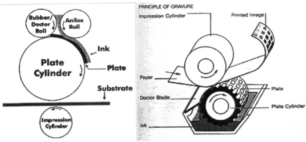
The printing machine is comprised of a plate cylinder, Anilox metering cylinder (flexography only), and ink pan. Gravure uses a third roller called a fountain roller or a "doctor blade" (for improving ink distribution).
laft
Hstat
Figure 3-3: Typical setups for flexography (left) and gravure (right)
Speeds vary considerably. Lower end machines advertise rates of 50-100m/min, while 300-600m/min or more is common on higher end machines. There are a variety of different configurations; following is an explanation of the most common:
* Stack
>
Vertical stacks with separate printing stations> Easy to interface other equipment like cutters, creasers, etc.
>
Poor registration* Central impression cylinder (CIC)
>
Single central impression cylinder surrounded color printing stations>
Precise registration, good color impressions * In-line>
Similar to stacked printing press, but horizontal>
Same problems and advantages as stack machine * Newspaper unit> Multiple printing stations arranged back to back to allow printing both sides at once in one pass
OQLYUO* 5 N ~a~M t~
mWIR OF 1OA-R 19
* Dedicated 4-, 5-, or 6-color commercial flexography press
>
Typically uses two 4-color units back to back > Infrared driers> Compact, high speed, wide web printing possible
Waste outputs during printing are similar for both gravure and flexography and include: Ink, wasted paper, old/outdated plates, solvents, and water.
3.2 Comparison between Micro-contact Printing and Traditional Printing
Techniques
3.2.1 Prepress
According to Nano-terra, masters costs about $100 when prepared in the lab including the silicon. However, one master can be used to produce many stamps, and each stamp can be used about 100 times. PDMS used to prepare the stamp is also inexpensive (~$75/kg.). High quality HDT (>99% purity) costs $200/g but the technical grade HDT costs only $10/g. Microcontact printing is still in its experimental lab stage, however, if utilized in mass-production scale economy will push these prices down.
3.2.2 Press
A variety of methods have been developed for the press operation in micro-contact printing. Machine costs vary greatly as the technology is in its infancy and most machines are one-off laboratory devices.
Quality is a major issue that is being evaluated and optimized by many companies and
universities. Minimum feature sizes achievable have been found to be about 40nm. While the
densities of defects in patterns of inks of alkanethiols formed by ACP have been evaluated, the
errors in registration of patterns produced by piCP have not been determined. There are three
primary sources of inaccuracies in pCP:
i.
In positioning the elastomeric element relative to the substrate
ii.
Intrinsic distortions of the element introduced during its fabrication
iii.
Distortions caused by elastic deformation of the element when it is brought into
contact with the substrate.
It has been demonstrated that when thin 0.1 mm elastomeric elements are cast against a rigid
backplane and the lithography is controlled with translation stages, absolute distortions are 500
nm over square areas 1 cm
2. When the lithography is performed by hand, relative distortions of
pairs of patterns can be as small as 500 nm over 0.25 cm2 if stiff, thick stamps are used. The
distortions in both of these cases are comparable to the limit of sensitivity of the measurements
[17].
At present, gCP is limited to thiols on metals such as Ag, Al and Cu. However, developments are
being made in printing of alkylsiloxanes on silicon dioxide and glass, as well as of copper and
polypyrrole on fluoropolymers. Other inks and substrates are also being developed.
The feasibility of continuous Micro-contact printing has already been demonstrated, so much so
that it can be carried out on tools that are currently employed for flexography at speeds as high as
100 feet/min [18]. Once developed this technology may be able to give good quality prints at
much higher speeds. Etching seems to the speed-limiting step in this process and solutions need
to be developed for incorporating continuous etching into pCP set-ups.
Waste outputs in gtCP include: chemicals used in photolithography for master manufacture,
PDMS waste, thiol inks, etchants, water, etc.
Table 3-1 Comparison of the three printing techniques: Gravure, Flexography and Micro-contact Printing
Gravure
Flexography
Micro-contact Printing
Setup-costs High Lower than Existing Flexography machines can be gravure modified. Still in experimental stages Stamp Scales Increases with If applied to mass production, the cost Costs linearly complexity and of the master can be amortized over
with sizes size many stamps making them cost effective.
Production Typically Similar to gravure Rates of 30.5 m/min have been Rate -500 demonstrated. However, it is possible
rn/min to achieve higher rates.
Runs Preferred Used mainly for Continuous micro-contact printing is for long medium to long being developed which can be used for runs runs. long runs.
Layer < 0.1-8
pm.
0.04-2.51nm. Single monolayer thickness Thickness Can give Constant filmprints with thickness. variable
film thickness.
Minimum 50-75pm 80pm Feature sizes as small as 5pm are
Feature possible.
Size
Registration > 20 < 200
Variety of inks and substrates are Mainly tor printing thlols on Au, Ag possible. and Cu. Alkylsiloxanes on glass; of
copper and polypyrrole on fluoropolymers has also been demonstrated.
Variety of waste outputs Alkanethiols and dialkyl sulfides are including chemicals for stamp irritants and have a strong odor. Health
production, inks, paper, etc. rating:2
4 Machine Design and Realization
In the machines design phase, we borrowed design ideas from traditional roll to roll printing
technique. Specialized tools as well as adjustment on processes were made according to the
characteristic of micro-contact printing and the requirement of on the speed and precision of the
machine. Three major machines were built, including a roll to roll printing machine, a roll to roll
etching machine and a large-scale stamp making fixture. Details of this design are in Stagnaro [7].
Modularity and inter-changeable are the two major ideas in our design philosophy. Modularity
enables quick adjustment of parameters (ex: wrap angle, real-time inking/cleaning assembly) and
provide flexibility in testing and optimization the machine. Subassembly can be tested
individually avoiding the hierarchical aggregation of possible problems. Modular design also
extended the value of the machine in the sense that many of the modules can be re-used in other
projects in the future. Using inter-changeable parts makes the manufacturing process easier by
reducing the work of design and assembly. For example, all the rollers except printing roller and
wind/rewind roller and bone rollers are of same design, all motor mounting plates are
inter-changeable, and there are only several major types of screws used on the whole machine.
4.1 Print Machine
The print machine is composed of three modules: supply module, print module and collect
module as shown in Figure 4-1.
Figure 4-1 Three Modules that compose the print machine
The components of each module are mounted to a base plate made from precision ground
aluminum to ensure alignment of all components within the subassembly and with other modules.
The three modules are mounted horizontally to a frame made from an extruded aluminum T-slot
framing system; the material flows left to right. Cantilevered rollers allow easy access to the
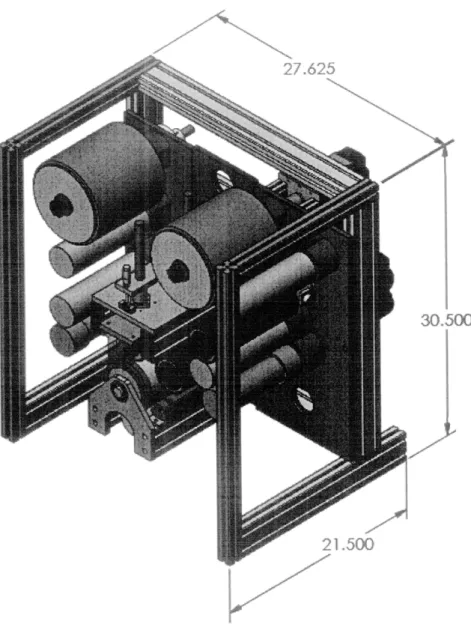
components. [7] Figure 4-2 shows a 3D view of the print machine in Solid Works.
Figure 4-2 3D view of the print machine
4.1.1 Print Module
The printing is the center part of the whole machine; it is where the substrate actually contacts with the PDMS stamp. Much of the most important functions of this machine are also on this module, including print, load, measure and adjustment, wrap angle adjustment, impression of the substrate, continuous inking and continuous stamp cleaning. So the design and quality of this part directly affects the printing quality. In this part, a stepper motor is connected to the printing roller driving the roller to run at the same line speed as the substrate during the print. An impression
30
roller wrapped with compliant sponge material and then a PET skin is used to apply load onto the substrate when it contacts with the print roller. A micrometer is used to adjust the load applied on the print area by the impression roller, and a load cell is used to measure this load in real time. A novel method for mounting steel backed stamps to cylinders is employed.[7] The mechanism of this module is shown in Figure 4-3.
IBWE NO. DESCRIPON GfY. 1 MOOULE PLATE. PRINT 1 2 BEARING BLOCK ASSY 2 3 INING ROLLER 1 4 STAMP ROLLER ASSY I S IMPRESSION ROLLER ASSY I 6 8020 STANDOFF 2 7 BEARING PLATE. PRINT I 8 BALL BEARING, IID 2' OD I 9 AIR KIFE MTG PLATE 1 10 AIR KNIFE 1 11 MOTOR STANDOFF 2 12 S1EPPER MOTOR NEMA34 1 13 MOTOR MOUNT PLATE 1
14 COUPLING _i
4.1.2
Supply Module
The supply module is mainly responsible for substrate unwinding and tension control. The main component is a base-plate machined from precision ground aluminum. Figure 4-4 is the exploded view of the supply module. The flatness of this plate ensures that all components are well aligned. There is no powered mechanism in this module, the tension control and web handling here are furnished by using the torque of two clutches one custom made friction clutch, serving as basic friction provider to the unwind roller, another is a permanent magnet clutch providing precise and finely adjustable tension control (tension control will be
DESCRIPION QTY.
I MOXULE PLATE SUPPLY 1
2 BEARING BLOCK ASSY 4
3 IDOER ROLER I 4 IDLER ROLLER 1 5 BONE ROLLER I 6 SPOOL ROLLER 1 7 KNOB 1 8 PM CLUTCH 1 9 MOTOR STANDOFF 2
10 SUBSTRATE SPOOL END 2
11 SUBSTRATE 1
12 WASHER, SPOOL 1
13 MOTOR MOUNT PLAIE 1
14 CLUTCH SHAFT 1
15 FRICTION CLUTCH ASSY 1 16 COUPUNG 1
Figure 4-4 An exploded View of the supply module
4.1.3 Collect Module
The collect module serves as prime mover for the whole system by pulling the substrate through the machine. It also controls the tension in the printing area to minimize the distortion from substrate stretching. Another major task of the collect module is to control the tension during the process of winding up the printed substrate. If no tension control is applied, the inside layer rolled up will be crushed by the outside roller due to increasing tension resulting from increasing
rEM NO. DESCRIPION QTY. 1 MODULE PLATE COLLECT 1 2 BEARING BLOCK ASSY 4 3 SPOOL ROLLER I 4 IDLER ROLLER 1 5 IDLER ROLLER I 6 BONE ROLLER 1 7 TRANSDUCER ROLL 2 8 WASHER. .750" ID 2 9 SHOULDER BOLT, .62S' 2 10 KNOB 1
11 STEPPER MOTOR NEMA34 2 12 MOTOR STANDOFF 4 13 WASHER, SPOOL 1 14 SUBSTRATE SPOOL END 2 15 SUBSTRATE 1
16 MOTOR MOUNT PLATE 2
17 COUPLING 2
Figure 4-5 An exploded view of the Collect Module
4.2 Etching Machine
Another machine we built other than the print machine was a continuous roll to roll etching machine which can synchronize with the print machine, serving as its subsequent step. Since etching is always the bottle neck of the speed in the industry and is the parameter determines the final quality of the product, the design should be able to keep up with the pace of the print
machine but use only limited amount of space. Another requirement on the etching machine is that, since the etching process is divided into several steps (ex: at Nano-terra there are 3 dipping and 2 drying), being able to control the time spent at each step is also a must. Considering all the above requirements, we come up with a modular design of the etching machine as shown in
Figure 4-6. The length of the trajectory of the substrate in the machine can be adjusted by lifting or lowing, along the linear bearing (red in Figure 4-6) the three rollers submerged in the etchant (green in Figure 4-6), thus the time spend in the machine can be changed under a given speed. Identical modules can be connected together to become a large etching machine, by changing the time that substrate spent in each stage independently, the modules can be combined as needed to fit etching process of any kind. Figure 4-7 shows a sample combination of the modules for an etching process.
Figure 4-6 A 3D view of the Etching Module
Supply Roll Colect Rol
Figure 4-7 A schematic of the module combination. Additional processing steps can be added by attaching more modules
When higher speed is required in the manufacturing (which will probably be the case eventually), we only need to simply expand the size of the etchant container (currently 12*12*12 inch3
) and add more rollers (current 8) or even easier, by adding one more module with identical function. The actual modification needed at different stage is shown below. For more detail about machine design please refer to Stagnaro [7].
1100 fPM'
Sub. Iangsi
(.W
mm a rerm r
Totl
8tAsatlergit
In pvas (Inchae)
4100
(ffeel
341.7
Figure 4-8 A design spreadsheet used to calculate the number of roller
EaMno,
lkM$
&ft IaPEldft~e
MWa8s
;
---
: ---
:-~-Foler OImalr ()
Us Speed,
I
5 Control System Design and Realization
The main functions of the control system are: (1) Over-all logical control of the system (2) Control the speed of printing (3) Control the tension at different parts of the machine. Over-all logical control is responsible for the routine operation of the system which is achieved using ladder logic program in a Programmable Logical Controller (PLC). Printing speed is controlled by changing the pulse signal fed into the stepper motors as well as the micro-stepping setting in the stepper motor. Tension control is one of the most important factors affecting both print quality
(especially distortion level) and the smooth operation of the machine.
5.1 Control System Overview
The control system is composed of 5 parts:
1. Programmable Logical Controller (PLC)
2. load cell
3. tension sensors (X2) 4. stepper motors (X3)
5. Power supply circuits
The PLC is the center of the control system, which is responsible for 2 on-line feed-back control loops for the tension control near printing roller and collecting roller, respectively. It also controls the generation of square voltage pulses which are fed into the stepper motors from three high-speed I/O ports and the collection real time printing load data from the load cell.
A DirectLogic06 PLC is used as the main controller, and the program is written in ladder logic. Three expansion modules were added: an analog IO unit and two high speed I/O (HSIO) modules.
The HSIO is used to provide step and direction signals to the drive and print stepper motors at
rates up to 25 KHz.
The aim of the feed-back control loops is to maintain constant tension on the substrate during the printing process and collecting process. This is due to the critical role tension plays in both the smooth operation of the printing machine and the quality (dimension and distortion) of the printed pattern.
Figure 5-1 DirectLogic06 PLC [20]
5.2 Control Program and Logic Flow
The program makes decisions based on tension data, programmed schemes and equations, and
inputs from buttons. The outputs are: motor instructions (step and direction), discrete operator
alerts, and ASCII text for data collection. The logic flow-chart of the whole program are as follow:
e
" " M -2 ",
"1 w lu- I|ial -1 "i'iIa I
--'I-,
I
. .I
Figure 5-2 Logic flow-chart of the PLC program
Page 49 T
-I
I I I I I I I I I I I I I I I I I I I I I I II I I I I I II I I II I I I I I II I I I I I I I I I I I I I I I I I I II I I I I II II I I I I I I 1 I I I I i5.3 PID Control Method Overview
PID is the acronym for "proportional-integral-derivative" controller, which is a type of feedback
control method widely used in industrial control systems. Like any other feedback-control system,
a PID controller attempts to correct the error between a measured process variable and a desired
set point by calculating and then outputting a corrective action that can adjust the process
accordingly [21].
The PID algorithm involves three parts, all of which contribute to the final corrective action:
correct the existing error (Proportional), average filtering of the historical error (Integral) and the
prediction of future error by the trend/rate of current error change (Derivative). The weighted sum
of these three actions is used to adjust the process via an actuator such as a valve or a servo motor.
The function of three parameters: P, I and D is depicted as follows:
Proportional
-
commonly referred to as Proportional Gain. The proportional term is the
corrective action which is proportional to the error, that is, the change of the manipulated variable
is equal to the proportional gain multiplied by the error.
Integral
-
often referred to as Reset action. It provides additional compensation to the control
output, which causes a change in proportion to the value of the error over a period of time. In
other words, the reset term is the integral sum of the error values over a period time.
Derivative
-
commonly referred to as rate. The rate action adds compensation to the control
output, which causes a change in proportion to the rate of change of error.
Let u(t) be the control signal sent to the system, y(t) the measured output and r(t) the desired
output. Then PID controller has the general form:
t
u(t) = Kpe(t)+ K e(r)d(r)+ K,
t)
0
In which, e(t) =
r(t)
-y(t)
is the difference between the set point and present output value. The desired closed loopand
dynamics is obtained by adjusting the three parameters Kp , KI
K,
Figure 5-3 Block diagram of PID controller
5.4 Feed-Back Tension Control System Design
5.4.1 Web Tension Control
Constant control of tension in a moving web is necessary to minimize the deformation of the web, ;as well as to maintain quality of printing. Generally the web is pulled off a large roll of substrates,

![Figure 2-2 Metallic multilayer pattern made by using the self assembly of polystyrene spheres as regular masks templates [9]](https://thumb-eu.123doks.com/thumbv2/123doknet/14677359.558296/21.918.298.621.220.472/figure-metallic-multilayer-pattern-assembly-polystyrene-spheres-templates.webp)

![Figure 2-9 Pattern fidelity (defects and pattern width) as a function of contact time [2]](https://thumb-eu.123doks.com/thumbv2/123doknet/14677359.558296/28.918.252.682.138.403/figure-pattern-fidelity-defects-pattern-width-function-contact.webp)
![Figure 3-1 Close-up of flexography stamp [3]](https://thumb-eu.123doks.com/thumbv2/123doknet/14677359.558296/30.918.256.693.297.627/figure-close-flexography-stamp.webp)