HAL Id: hal-01722100
https://hal.archives-ouvertes.fr/hal-01722100
Submitted on 2 Mar 2018HAL is a multi-disciplinary open access archive for the deposit and dissemination of sci-entific research documents, whether they are pub-lished or not. The documents may come from teaching and research institutions in France or abroad, or from public or private research centers.
L’archive ouverte pluridisciplinaire HAL, est destinée au dépôt et à la diffusion de documents scientifiques de niveau recherche, publiés ou non, émanant des établissements d’enseignement et de recherche français ou étrangers, des laboratoires publics ou privés.
Public Domain
Hydromechanical modeling of concrete under high
confinement: modelling, validation, simulations
Christophe Pontiroli, He Yang, Yun Jia, Jianfu Shao
To cite this version:
Christophe Pontiroli, He Yang, Yun Jia, Jianfu Shao. Hydromechanical modeling of concrete under high confinement: modelling, validation, simulations. 11e colloque national en calcul des structures, CSMA, May 2013, Giens, France. �hal-01722100�
CSMA 2013
11e Colloque National en Calcul des Structures13-17 Mai 2013
Hydromechanical modeling of concrete under high confinement:
modelling, validation, simulations
Christophe Pontiroli1 *, He Yang2, Yun Jia 2, JianFu Shao2
1 CEA, DAM, GRAMAT, F-46500, Gramat, France, [email protected] 2
Laboratory of Mechanics of Lille, Polytech’Lille, Cité scientifique, 59655 Villeneuve d’Ascq, France
Abstract — A new constitutive model is proposed for the description of the coupled elasto-plastic-damage behaviour of concrete under a wide range of confining pressure. Based on experimental investigation, two plastic flow mechanisms are identified: plastic shear mechanism at low confining pressure and plastic pore collapse mechanism at high confining pressure. Furthermore, the increase of water saturation in concrete structure induces the diminution of capillary pressure in liquid contact which leads to an additional plastic deformation. Consequently, influence of water saturation state on the mechanical behaviour is also studied in this paper. This model is validated by comparisons with triaxial compressive tests conducted on concrete specimen with GIGA press at the laboratory 3S-R (Université Joseph Fourier - Grenoble). Then, simulations of dynamic penetration tests with rigid projectile on concrete slabs were carried out so as to validate numerical approach.
Keywords — concrete behaviour, hydromechanical modeling, numerical simulations, penetration
1.
Introduction
Concrete is the most widely used manufactured material in many types of engineering structures (hydraulic dams, nuclear power plants and civil engineering structure…etc). The mechanical behaviour of concrete is still rather poorly studied, especially under extreme loading. In particular, when the structure is subjected to near-field detonations or ballistic impacts, very high-intensity triaxial stress is developing locally. In order to evaluate the mechanical behaviour of concrete under such high confining pressure, extensive experimental investigations and numerical simulations are necessary.
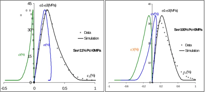
For few years, experimental tests have been performed on concrete with confining pressure up to 650 MPa by mean of a high-capacity hydraulic triaxial press, called "GIGA" press and located at laboratory 3S-R at Grenoble [1], [2]. This experimental device makes it possible to reach, within the samples, stress levels on the order of one GPa with static, homogeneous and well-controlled load paths. These works have shown that, under high confining pressure, the degradation of material stiffness is significantly reduced and an important pore collapse process is developed in material. The increase in confining pressure leads to a change in the macroscopic mode of failure, i.e. form brittle to ductile behaviour. Furthermore, the mechanical behaviour of concrete is strongly sensitive to the water saturation degree. The saturation of concrete by water could induce pore collapse and substantial plastic deformation [2]. In conclusion, these works have shown that the mechanical behaviour of concrete is very complex, and characterized by various features: low material cohesion, strong pressure sensitivity, pore collapse process, dependency on porosity and water saturation states. Figure 1 shows the effect of saturation ratio on concrete volumetric and deviatoric behaviour.
From those observations a new elastoplastic model coupled with damage for the description of mechanical behaviour of concrete has been developed. The verification of the proposed model is presented by comparing numerical simulations and experimental data obtained under triaxial compressive loadings in saturated and dried conditions.
deceleration, residual velocities and crack pattern have been recorded to validate the presented numerical model.
Fig. 1 : Effect of saturation ratio on concrete volumetric and deviatoric behaviour [2]
2.
Modelling
A new coupled elastic-plastic-damage model has been developed at Laboratory of Mechanics of Lille. In this paper, the general framework of this model is firstly proposed by for quasi-dry porous media. Afterward, based on the experimental investigation, a unified model is proposed for quasi-dry concrete under different confining pressure (up to 650 MPa). Furthermore, the strong influence of water saturation state on the concrete behaviour is taken into account in the framework of partially saturated porous media.
2.1. Coupled elastoplastic damage model for dry cementitious material
Triaxial compressive tests conducted with GIGA press for different confining levels have shown different damage and plastic mechanisms in concrete behaviour [1], [2]. Under low confining pressure, the basic behavior of concrete is brittle elastic or brittle elastoplastic. The material fails under limiting stress. A damage model can reproduce typical failure modes of concrete (i.e. cracking in tension and crushing in compression) under uniaxial tension and compression conditions. As the confining pressure increase, there is a transition from brittle to ductile behaviour. At high confining pressures, when the mean stress reaches a limit value, an irreversible volumetric strain is produced, corresponding to the phase of plastic collapse of pore structure. Finally, it is decided to use a plastic damage model with two plastic mechanisms for the mechanical behaviour of concrete: a shear plastic mechanism under low confining pressure and a pore collapse mechanism under high confining pressure.
In this section, an elasto-plastic-damage model for concrete failure is developed. The plastic part of the proposed model is based on the normal stress and defined by the yield function, the flow rule and the evolution law for the hardening variable. The damage model is based on the plastic strain and consists in the damage criterion and the damage law.
Damage characterizing:
To take into account the difference between tensile (maximum strength=2-3 MPa) and compressive (maximum strength=30-40 MPa) behaviour of a normal concrete, the tensile damage ωt is controlled
by an equivalent tensile strain εeq while the compressive damage ωc is dominated by the total
deviatoric strain γ.
Inspired from the damage model proposed by Mazars [3],the tensile damage criterion ftw and the
( )
1
(
,0)
1
0;
max
,
exp
t t t t t eq tf
Y
Y
B Y
ω ω ω ωω
ε
=
− −
=
=
(
1
)
(
,0)
1
0;
max
,
exp
c c c c c cf
Y
Y
B Y
ω ω ω ωω
γ
=
− −
=
=
,0 tYω
and
Yωc,0are respectively the initial thresholds of damage in tension and compression.
The parametersBc and Bt respectively control the evolution kinetics of the compressive and tensile damage.
In order to account for unilateral effects (cracks opening and closure), the global damage effects are represented by the following global damage coefficient:
(
1
t)
c t tω
= −
α ω α ω
+
The αt and αc coefficients, which depend on the stress state, determine different effects of tensile
and compressive damage (αt + αc=1).
Plastic pore collapse characterizing:
Under high confining pressure, the plastic pore collapse induces an increase of contact surface between grains, which leads to a plastic hardening phase. Inspired by the plastic model proposed by Gurson [4], the following plastic yield function is expressed as the basic yield function of the pore collapse mechanism:
(
)
2 2 1 23
, ,
2 cosh
1
0
2
cq
p
f
σ φ
φ
q
φ
σ
σ
=
+
− −
=
σσσσ
3( )
( )
21
;
;
3
3
tr
q
=
ss s
= −
σ
σ
σ
σ
σσσσ
δ
δ
δ
δ
p
=
tr
σ
σ
σ
σ
where
q
denotes the equivalent deviatoric stress.q
1 is a material parameter which determines the geomaterial form of yield surface.φ
represents the porosity of concrete.The coefficient
σ
represents the plastic yield stress of concrete solid matrix, which depends on the mechanical properties of solid grains and the various contact forces.Based on the experimental investigation from hydrostatic phase of triaxial compression test, a plastic isotropic hardening law is proposed for plastic collapse mechanism:
0
1
(
)
pc M b pc n Ma
e
εσ σ
=
+
ε
whereε
pcM is the plastic volumetric strain due to the pore collapse process
ε
pcM=tr(
ε
pc), taken as the
internal hardening.
0
σ
denotes the initial yield stress of solid matrix.a, n
andb
are three parameters of the hardening law, which can be identified form an hydrostatic test.The yield function of pore collapse process depends also on the connected porosity of concrete. By assuming that the plastic compressibility of solid grains may be neglected, the porosity change is expressed as following:
(
1)
tr( )
pcφ
&= −φ
εεεε
&In order to describe the plastic volumetric deformation, a non-associated plastic flow rule is developed for the pore collapse process in concrete. By taking a similar form as the yield function, the following function is proposed as the plastic potential:
(
)
2 1 23
, ,
2 cosh
2
cq
p
Q
σ φ
φ
q
σ
σ
=
+
σσσσ
Plastic shear characterizing:
According to experimental data for concrete in various loading paths, a curved yield surface is necessary in order to take into account the strong pressure dependence. Consequently, the following yield function is used:
(
, , ,)
( )(
)
0 1.0 ps s lq s s r A f S q g p C p B p ω γ ω α θ = + − = − σσσσwith p the mean stress (positive in compression), q the deviatoric stress, both associated to the effective stress tensor, Slq denotes water saturation. The function g(θ) defines the dependency of yield
function on the Lode angle. In the absence of relevant data and for the sake of simplicity, the function g(θ) is taken equal to 1. The coefficient pr is a normalizing coefficient taken here to be equal to 1
MPa, and Cs denotes the coefficient of cohesion of dry material. In the case with B=0, this simplified
case of the proposed model is equivalent to the classical Drucker-Prager type model which is widely used in geomaterials.
In the proposed model, the post-peak softening is controlled by the damage evolution. Consequently, the failure surface increases with plastic distortion γps and decreases with the damage growth ω. The
plastic hardening law is proposed as following:
αs = (1-ω)[1.0-(1.0-α 0 s)e -ζγps ] and αωs = (1-ω)αs ; p ps ps ps
ε
ε
χ
γ
/
3
2
∫
=
&
&
1 ; 3 3 ps ps ps kk p r r r q p p p p βε δ χ
′ = − = − − + εεεε
eThe parameter ζ controls the rate of plastic hardening. The function χp is introduced in order to better
describe the strong pressure sensitivity of plastic hardening in concrete, which is controlled by the parameter β1.
In order to describe the transition from plastic volumetric compressibility to dilatancy with the increase of the applied deviatoric stress, a non-associated plastic flow rule has to be defined. Based on experimental observation [5], the following plastic potential is used:
(
)
(
)
( )
0,
ps,
1
ln
0;
s s sI
Q
q
g
I
I
p C
I
σ γ ω
= + −
ω µ
θ
=
= −
The parameter I0 defines the intersection of the plastic potential surface with the p axis. The boundary
between compressibility and dilatancy domains is defined by the condition ∂Qs/∂p = 0 which is
expressed as following:
(
1
)
( )(
)
0
s s s
f
ω= − −
q
ω µ
g
θ
p C
−
=
The parameter µs defines the slope of the boundary between compressibility and dilatancy zones.
2.2. Extension to saturated and partially saturated conditions
As indicated in experimental data, the mechanical behaviour of concrete is very sensitive to water saturation degree. The main factor of this dependency is the variation of capillary pressure during variation of hydraulic condition. The cimentitious material can be assimilated to an isotropic porous medium saturated by a liquid water phase (noted by index lq) and a gas mixture phase (noted by index gz). The gas mixture is a perfect mixture of dry air (noted by index da) and vapor (noted by index va). Denoting pα the pressure of the fluid phase α (α=lq,va, da), the pressure of gas mixture pgz
is expressed by the following relation:
gz vp da
p& = p& + p& The capillary pressure pcpis defined as follow:
cp gz lq
p& = p& −p&
Based on the previous works by Coussy et al. [6], [7], the effects of liquid and gas pressure are characterized by an equivalent pore pressure:
( )
gz lq cp cp
p S p p
π
&= & − &;
π
=∫
π
&Slq denotes water saturation. Using this equivalent pore pressure, the elastic constitutive relations for a
partially saturated concrete are expressed as:
( )
2( )
( )
( )
( )
2 3 e e Kω
µ ω
trµ ω
bω π
= − + − σ
ε δ
ε
δ
σ
σ
ε δ
ε δ
ε
ε
δ
δ
σ
ε δ
ε
δ
In the case of Slq=1, the formulation for saturated concrete is obtained.
Based on the concept of net stress (total mean stress plus gas pressure), proposed by Alonso et al. [8] and called Barcelona method, the capillary pressure is used as a complementary force variable. Elastic properties and plastic functions explicitly depend on this capillary pressure.
For example, to take into account the water saturation degree which affects the plastic yield stress of the plastic pore collapse mechanism, the hardening function for partially saturated or saturated concrete can be expressed as follows:
] ) ( 1 [ ( ) 0 pc M lq b S n pc M e a
ε
εσ
σ
= + with ) 1 exp( ) ( ) ( 0 0 lq lq n s lq S S n n n S n − − − − =ζ
The function n(Slq) varies from the asymptotic value for dry concrete n0 to the asymptotic value for
fully water saturated concrete ns.
An important advantage of this model concerns its explicit formulation where the stress tensor can be directly established knowing the total strain tensor.
2.3
Validation
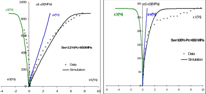
The simulations of uniaxial, hydrostatic and triaxial compression tests on a dried (saturation ratio=11%) and saturated (saturation ratio=100%) concrete specimen have been performed. Some representative results are shown in Fig. 2 and Fig. 3. The influence of water saturation on the mechanical behaviour of concrete is correctly reproduced by the proposed model. In conclusion, the proposed model is capable to reproduce the hydromechanical behaviour of concrete under a large range of confining pressure.
Fig. 2 : Uniaxial compression test for a dried and saturated concrete sample
Sw=11% Pc=0MPa 0 15 30 45 -0.5 0 0.5 1 Data Simulation σ1-σ3(MPa) ε1(%) ε3(%) εv(%) Sw=100% Pc=0MPa 0 10 20 30 40 -1 -0.6 -0.2 0.2 0.6 1 Data Simulation σ1-σ3(MPa) ε1(%) ε3(%) εv(%)
Fig. 3 : Triaxial compression test for a dried and saturated concrete sample at a confining pressure of 650 MPa
3.
Penetration experiments
CEA-Gramat has conducted penetration tests with a 2.4 kg ogival nose projectile (CRH=5.77, L/D = 5.77 and D°= 52 mm) launched into a cylindrical unreinforced concrete block 800 mm thick and 800 mm in diameter. 35NCD16 steel projectile is designed to mount an acceleration recorder system inside to measure the axial deceleration during the tests.
Experimental instrumentation is completed by using high speed video cameras to observe the interaction between the projectile and the target. After firing, a topographic laser system allows to measure the dimensions of crater created by spalling and tunnelling mechanisms during projectile penetration.
The figure 4 shows the gas launcher “DEIMOS” at CEA-Gramat and the projectile with its recorder system. Tests have been performed with different impact velocities (from 225 to 425 m/s).
Fig. 4 : Gas launcher and rigid projectile with its acceleration recorder system
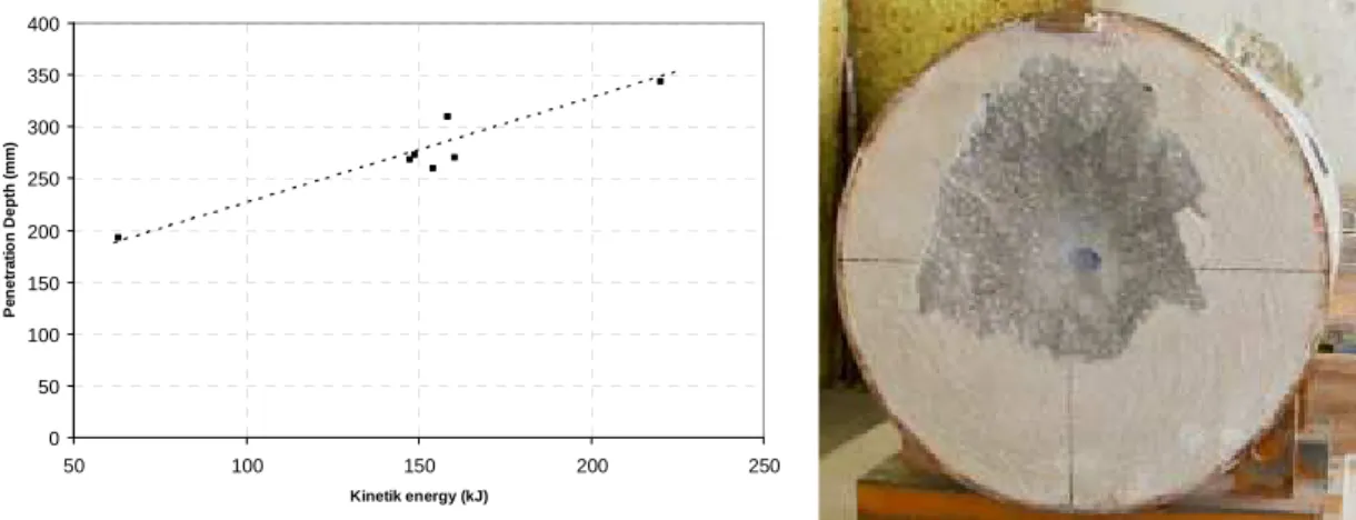
A standard concrete mixture named R30A7, defined several years ago by CEA-Gramat and Laboratory 3SR at Grenoble, has been used for concrete slabs. The tested R30A7 concrete displays a 28-day compressive strength of 30 MPa. It should be noted that a very high-quality cement is used. This high quality gives better material reproducibility and leads to a particularly low cement volume. Aggregate compounds, with a maximum size of 8 mm are derived from natural deposits (rolled aggregates, 99% quartzite).
Cylindrical unreinforced concrete targets have been casted and conserved in water until penetration tests (concrete can be considered as completely saturated). A steel ring around the cylindrical target allows to confine concrete during projectile impact.
Fig. 5 shows results in terms of penetration depth versus initial projectile kinetic energy. Penetration capacity varies linearly with the initial velocity of projectile. The mechanisms of spalling and
Sw=100% Pc=650 MPa 0 50 100 150 200 250 300 -6 -4 -2 0 2 4 6 8 10 Data Simulation ε1(%) σ1-σ3(MPa) ε3 ε3 ε3 ε3(%) εεεεv(%) Sw=11% Pc=650MPa 0 200 400 600 800 1000 -4 -2 0 2 4 6 8 10 Data Simulation e1(%) e3(%) σ1-σ3(MPa) ε3(%) εv(%)
0 50 100 150 200 250 300 350 400 50 100 150 200 250 Kinetik energy (kJ) P e n e tr a ti o n D e p th ( m m )
Fig. 5 : Penetration depth versus initial kinetic energy and front face of target after shot (Vi=227 m/s)
4.
Simulations
Concrete model presented in this paper has been implemented in Abaqus/Explicit v12 [9]. 2D axisymmetric finite elements are used for concrete modelling, the projectile is assumed to behave as a rigid body. Two penetration tests have been simulated, one with an initial velocity of 227 m/s and one with 347 m/s.
Fig. 6 and Fig. 7 give respectively the temporal evolutions of the projectile deceleration and penetration depth for an initial projectile velocity of 227 and 347 m/s. Experimental and numerical comparisons show a good agreement although an over-prediction of the penetration in the computation. Penetration depths obtained numerically are about 211 mm for 227 m/s (193 mm experimentally) and about 347 mm for 347 m/s (268 mm experimentally). Strain rate effects on penetration mechanisms, not take into account in our concrete model, can explain such difference
Fig. 6 : Evolution of the projectile deceleration and the penetration depth (Vi=227 m/s)
Fig. 7 : Evolution of the projectile deceleration and the penetration depth (Vi=347 m/s)
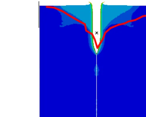
Fig. 8 shows experimental crater measures in red line (obtained by topographic laser system) and
-25000 -20000 -15000 -10000 -5000 0 0 0.2 0.4 0.6 0.8 1 1.2 1.4 1.6 1.8 2 Experiment Simulation Time(µµµµs) Acceleration(g) -25000 -20000 -15000 -10000 -5000 0 0 0.2 0.4 0.6 0.8 1 1.2 1.4 1.6 1.8 2 Experiment Simulation Time(µµµµs) Acceleration(g) 0 0.1 0.2 0.3 0 0.2 0.4 0.6 0.8 1 1.2 1.4 1.6 1.8 2 Experiment Simulation Time(µµµµs) Penetration(m) 0 0.1 0.2 0.3 0 0.2 0.4 0.6 0.8 1 1.2 1.4 1.6 1.8 2 Experiment Simulation Time(µµµµs) Penetration(m) -35000 -30000 -25000 -20000 -15000 -10000 -5000 0 0 0.2 0.4 0.6 0.8 1 1.2 1.4 1.6 1.8 2 Experiment Simulation Time(µµµµs) Acceleration(g) -35000 -30000 -25000 -20000 -15000 -10000 -5000 0 0 0.2 0.4 0.6 0.8 1 1.2 1.4 1.6 1.8 2 Experiment Simulation Time(µµµµs) Acceleration(g) 0 0.1 0.2 0.3 0.4 0 0.2 0.4 0.6 0.8 1 1.2 1.4 1.6 1.8 2 Experiment Simulation Time(µµµµs) Penetration(m) 0 0.1 0.2 0.3 0.4 0 0.2 0.4 0.6 0.8 1 1.2 1.4 1.6 1.8 2 Experiment Simulation Time(µµµµs) Penetration(m)
Fig. 8 : Experimental (in red) and numerical comparisons of crater dimensions for Vi=227 m/s and 447 m/s
5.
Conclusions
Based on a phenomelogical analysis of a large experimental database of triaxial tests on dried and saturated concrete, a hydromechanical model has been developed. Two plastic deformation mechanisms and damage mechanism have been taken into consideration: plastic shearing and damage developed under low confining pressure and plastic pore collapse deformation observed under high confining pressure. The simulations of GIGA press tests, performed on various loading paths have shown a good agreement with experimental data. The proposed model is able to describe the main features of poromechanical behaviours for the concrete, such as irreversible deformation and pressure sensitivity (i.e. transition from volumetric compressibility to dilatancy and damage which develops under low confining pressure; pore collapse developed under high confining pressure).
Comparisons with experimental penetration results have shown the capacity to the presented model to reproduce the response of concrete under high confinement. However, some discrepancies remain to obtain more accurate penetration depth and spalling phenomena. It may be related to the absence of a strain rate dependency mechanism in our concrete model [10].
Acknowledgements
This work was supported by the French Ministry of Defense, through DGA/UM-MID. The authors gratefully acknowledge laboratories implied in the research network PREVI “Pôle de Recherche et d’Etudes sur la Vulnérabilité des Infrastructures”.
6.
References
[1] T. Gabet, Y. Malécot, L. Daudeville. Triaxial behavior of concrete under high stresses: Influence of the loading path on compaction and limit states. Cement and Concrete Research 38 (3), 403-412, 2008.
[2] X.H. Vu., Y. Malecot, L. Daudeville., E. Buzaud. Experimental analysis of concrete behavior under high confinement: Effect of the saturation ratio. International Journal of Solids and Structures, doi: 10.1016/j.ijsolstr.2008.10.015, 2008.
[3] Mazars,J. (1984). Application de la mécanique de l’endommagement au comportement non linéaire et à la rupture du béton de structure, Thèse de Doctorat Sciences, Université Paris 6, France.
[4] A.L. Gurson, 1977, Continuum Theory of Ductile Rupture by Void Nucleation and Growth: Part I - Yield Criteria and Flow Rules for Porous Ductile Media, Transactions of the ASME.
[5] Shao J.F., Jia Y., Kondo D. and Chiarelli A.S. (2006): A coupled elastoplastic damage model for semi-brittle materials and extension to unsaturated conditions, Mechanics of Materials, 38, 218-232
[6] Coussy O., Dormieux L., Detournay E., 1998. From mixture theory to biot's approach for porous media, Int. Journal of Solids and Structures, Vol.35, pp.4619-4635.
[7] Coussy O. (2004). Poromechanics. John Wiley & Sons
[8] Alonso E. E., Gens A. and Josa A. (1990). A constitutive model for partially saturated soils. Géotechnique 40 (3), 405-430
[9] Simulia (2011); Abaqus version 6.11 documentation. Dassault Systèmes Simulia Corp.
![Fig. 1 : Effect of saturation ratio on concrete volumetric and deviatoric behaviour [2]](https://thumb-eu.123doks.com/thumbv2/123doknet/12724128.356871/3.892.123.781.124.371/fig-effect-saturation-ratio-concrete-volumetric-deviatoric-behaviour.webp)