HAL Id: hal-02046493
https://hal.archives-ouvertes.fr/hal-02046493
Submitted on 22 Feb 2019
HAL is a multi-disciplinary open access
archive for the deposit and dissemination of
sci-entific research documents, whether they are
pub-lished or not. The documents may come from
teaching and research institutions in France or
abroad, or from public or private research centers.
L’archive ouverte pluridisciplinaire HAL, est
destinée au dépôt et à la diffusion de documents
scientifiques de niveau recherche, publiés ou non,
émanant des établissements d’enseignement et de
recherche français ou étrangers, des laboratoires
publics ou privés.
surface-piercing bodies by integral matching method
Vincent Rey, G. Arnaud, Julien Touboul, Kostas Belibassakis
To cite this version:
Vincent Rey, G. Arnaud, Julien Touboul, Kostas Belibassakis. Water wave scattering by dense or
sparse arrays of surface-piercing bodies by integral matching method. Applied Ocean Research,
Else-vier, 2018, 75, pp.132-142. �10.1016/j.apor.2018.03.012�. �hal-02046493�
Contents lists available atScienceDirect
Applied Ocean Research
journal homepage:www.elsevier.com/locate/apor
Water wave scattering by dense or sparse arrays of surface-piercing bodies
by integral matching method
V. Rey
a,b,⁎, G. Arnaud
a,b, J. Touboul
a,b, K. Belibassakis
caUniversité de Toulon, CNRS/INSU, IRD, Mediterranean Institute of Oceanography (MIO), UM 110, 83041 Toulon Cedex, France bAix-Marseille Université, CNRS/INSU, IRD, Mediterranean Institute of Oceanography (MIO), UM 110, 13288 Marseille, France cSchool of Naval Architecture and Marine Engineering, National Technical University of Athens, Zografos, 15773 Athens, Greece
A R T I C L E I N F O
Keywords: Water waves Scattering
Vertical cylindrical arrays Integral matching method Interference process
A B S T R A C T
In this work, integral matching method is used for the numerical study of water wave scattering by arrays of surface-piercing structures. Such a method, already used for many years for rectangular breakwaters, is applied to structures of various shapes, including arrays of vertical cylinders, for which the contour of vertical bound-aries is discretized into steps. Finite width channels of constant depth are considered, which may also correspond to uneven periodic structures along the transverse direction. Applications to sparse or dense arrays of vertical cylinders are discussed. For sparse cylinders,first order and higher order Bragg resonance are observed in both the incoming wave direction and other directions for the higher frequencies. For dense cylinders, considered as porous media, dispersion relation for the wave within the cylinders arrays is discussed through interference process due to thefinite length of the porous medium (or the cylinders array) along the incoming wave direction. It is found that the wavelength slightly depends on the cylinders arrangement at given porosity and specific surface.
1. Introduction
During the last decades, a huge effort has been made to better un-derstand and model water waves propagation through inhomogeneous media and their interaction with ocean and coastal structures. Arrays of vertically emerging bodies have been widely studied in ocean en-gineering in the context of wave diffraction by cylinder arrays and wave loads on these structures (see e.g. [1,2] and references cited there) and in coastal engineering for shore sheltering by detached offshore breakwaters of rectangular shape through wave scattering and dis-sipation [3,4]. For environmental purpose, emergent wetland vegeta-tion can be modelled by dense arrays of vertical cylinders across which wave propagates with significant damping ([5] and references cited). Such permeable bodies of finite extent which may also be used in coastal engineering for sheltering the shore since a part of the incoming energy may be reflected through interference process in addition to the dissipation process ([6,7] and references cited there for a more com-plete review).
For single or sparse vertical cylinders of circular cross section, analytical solutions exist and take advantage of the axial symmetry (see [8]). For an array of cylinders, approaches from sparse cylinders for which plane wave approximation can be used (see e.g. [9]) to denser
arrays where interference between adjacent bodies have to be con-sidered, various analytical or numerical solutions are proposed (see [10] and references cited there). Linton and Evans [11] solved exactly the problem of wave scattering by arrays of vertical cylinders through the use of a simplified expression of the velocity potential in the vicinity of a cylinder. When dissipation effects are concerned for rather dense arrays of cylinders, semi-analytical solutions based on multi-scale anaysis can be used as proposed by Mei et al. [6]. In the latter works, dissipation is considered at the scale of the bodies, while both the diameter of the bodies and the distance between adjacent bodies remain small compared to wavelength. Since permeability remains large en-ough to allow wave to propagate across the arrays of cylinders, inter-ference process and wave scattering may be observed, leading to dif-fraction depending on the cylinder diameter and spacing when wavelenth is of the order of cylinders spacings. For longer waves of wavelength of the order of the array of cylinders, reflection due to the finite extend of the array in the incoming wave direction may be ob-served [6,7]. Such interference processes are related to the wave wa-velength. The dispersion relation in the presence of vertical cylinders was recently discussed by Molin et al. [12] using results from sloshing experiments within a tank at resonant conditions.
Vertical cylinders of rectangular cross section are often considered
https://doi.org/10.1016/j.apor.2018.03.012
Received 17 November 2017; Received in revised form 1 February 2018; Accepted 22 March 2018
⁎Corresponding author at: Université de Toulon, CNRS/INSU, IRD, Mediterranean Institute of Oceanography (MIO), UM 110, 83041 Toulon Cedex, France.
E-mail address:rey@univ-tln.fr(V. Rey).
Available online 31 March 2018
0141-1187/ © 2018 Elsevier Ltd. All rights reserved.
as an academic case to model breakwaters in coastal engineering. Wave field around a detached breakwater on a plane beach of constant slope is described in [13]. Diffraction effects are significant in the case con-sidered since the wave wavelength is of the order of the breakwater width. When considering breakwaters along shoreline, the gap between adjacent breakwaters is also a key parameter for the wave diffraction process, as shown by Dalrymple and Martin [3] for normal wave in-cidence and by Abul-Azm and Williams [4] for oblique wave incidence for thin breakwaters and constant depth conditions. If breakwaters are of uniform geometry and gaps identical, the geometrical domain re-duces to a channel of width equal to the periodicity of the breakwaters. Since boundaries are rectilinear, cartesian coordinates are employed, and an eigenfunction expansion method is used for the solution, based on matching conditions of continuity at the gap location for the wave, written as the sum of the incoming (or transmitted) wave and addi-tional modes, which correspond to either scattered wave modes or evanescent modes. The number of scattered modes depends on the channel width. In the case of rectangular body within a channel, trapped modes were evidenced for a vertical cylinder of rectangular cross-section [14], or for more generally for bodies of different shapes [15].
Under the assumptions that thefluid is incompressible and inviscid, and that its motion is irrotational, a general expression for the velocity potential can then be defined in waters of constant depth in a cartesian frame, as proposed for instance by Dalrymple and Martin [3]. If wave propagates across successive rectangular domains of variable width, the solution for the potential can be obtained by means of pressure andflow matching conditions at each interface between successive domains though an integral matching method. Such a method is also well known for wave propagation in the presence of abrupt variations of the depth in the two-dimensional case. In the case of smooth bottom variations, this method is still valid for the calculation of both reflected and transmitted waves [16,17] even if the velocityfield is not valid near the boundaries discretized in successive steps but can be improved by use of an additive term in the potential expansion [18]. In the present study, integral matching method is used for the study of wave scattering by surface piercing cylinders with vertical walls and of any cross-section shape. Indeed, for smooth cross-sections shapes including circles, a discretization of the contour is done to obtain rectangular domains.
In Section2, the theoretical model and the numerical formulation are presented. Results and comparisons to previous studies are then reported and discussed in Section3. Concluding remarks are then given in Section4.
2. Theoretical model and numerical formulation 2.1. Linear potential theory
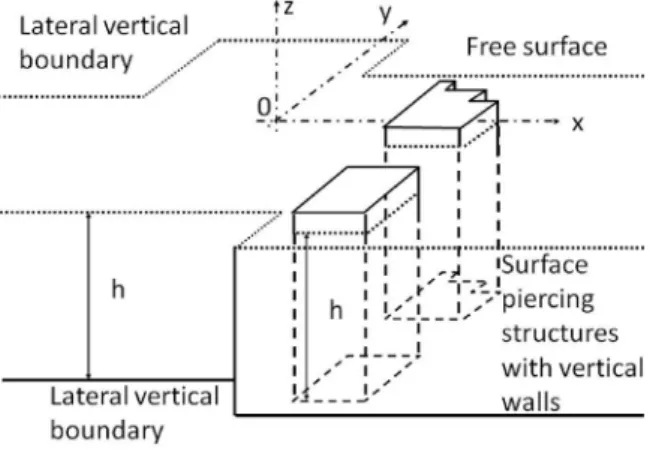
Wave is assumed to propagate along a channel of constant depth h and variable width. Surface piercing structures can be of irregular shape in the horizontal plane, their shape does not depend on the vertical direction, and boundaries are then vertical walls as shown inFig. 1. A coordinate systel is considered with origin at some point at the mean free surface and z axis pointing upwards. For smooth surface contours, as for instance vertical cylinders, discretization into steps will be done. For unbounded periodic structure arrangements along y-axis, condi-tions of symmetry will allow to further consider geometrical domains bounded along y-axis. In the following, the incoming wave propagates along x-axis, towards x > 0. Scattered waves propagate in the channel outwards the structure.
2.1.1. General expressions for the velocity potential within domains offinite width
In the linear problem, a general expression of the velocity potential in a cartesian frameΦ(x, y, z, t) for a regular wave of angular frequency ω propagating over a constant water depth h is of the form
= + + Φ x y z t αω k k z h F x y e ( , , , ) cosh[ ( )] sinh(kh) ( , ) cc iωt (1) where α is the amplitude of free surface elevation. Wavenumber k verifies the dispersion relation:
=
ω2 gk tanh(kh) (2)
Considering thefluid domain to be bounded along y-axis in the interval dm< y < dM, with d = dM− dm the width of the channel, velocity
potential(1)takes the form
= + +
Φ x y z t( , , , ) cosh[ (k z h ϕ x y e)] ( , ) iωt cc (3) with the free surface potentialϕ(x, y) given by
∑
= + = ∞ − − + + ϕ x y( , ) [A e A e ]ψ y( ) n n x n x n 0 ikxn ikxn (4) where = − ψ yn( ) cos[kyn(y dm)] (5) and = − = k nπ d d nπ d M m yn (6) since noflux conditions are required at y = dmand y = dM.SinceΔΦ = 0, where = ∂ ∂ ∂ ∂ ∂ ∂
(
)
Δ , , x y z 2 2 2 2 2 2 , = − kxn (k2 kyn2)1/2 (7)For n = 0, kxn= k, and kxnis purely imaginary for kyn> k. The number
of propagating modes npropis then given by
= + ⎡ ⎣ ⎤ ⎦ n π 1 Int kd prop (8) with Int denoting the integer part. For propagating modes n along x-axis, kxn= k cosθnand kyn= k sinθn, whereθnis the angle of
propa-gation with respect to the x-axis at given mode n. For narrow channels or long waves ( <k −π
dM dm), only thefirst mode propagates along x-axis,
the other are evanescent along x-axis. For the numerical processing, general expression of the velocity potential is truncated at a given order n = P, thefirst (P + 1) modes are hence considered. For simplicity, P will be chosen the same for all the domains in the following calcula-tions.
2.1.2. Equations of continuity for a single channel
For two successive domains (see Fig. 2) labelled 1 and 2, of re-spective widths d1= dM1− dm1(dm1< y < dM1) and d2= dM2− dm2
(dm2< y < dM2), velocity and pressure matching conditions at their
interface x = x0are the following:
⎧ ⎨ ⎪ ⎪ ⎩ ⎪ ⎪ = ⩽ ⩽ = ⩽ ⩽ = ⩽ ⩽ ⩽ ⩽ = ∂ ∂ ∂ ∂ ∂ ∂ ϕ ϕ d d y d d d d y d d d y d d d d y d j
for max( , ) min( , )
for max( , ) min( , )
0 for max( , ) and min( , )
, 1, 2 m m M M ϕ x ϕ x m m M M ϕ x m m M M 1 2 1 2 1 2 1 2 1 2 mj 1 2 1 2 Mj j 1 2 (9) Functionsψj,m,ψj,nform an orthogonal system for the scalar product
∫
= f gj j f.gdy d d j j mj Mj (10) Taking advantage of the orthogonal set of functions ψj,m, interfaceconditions are written in an integral form, for any n. In the case dm1⩽ dm2and dM2⩽ dM1depicted inFig. 2, conditions are given by
∫
ϕ ψ. dy=∫
ϕ.ψ dy d d n d d n 1 2, 2 2, m M m M 2 2 2 2 (11) and∫
∂∂ =∫
∂ ∂ ϕ x ψ ϕ x ψ . dy . dy d d n d d n 1 1, 2 1, m M m M 1 1 2 2 (12) for n = 0,…, P. In the following, we will only considerer domains of single channel thanks to the symmetries along y-axis. For multiple channels, one may write in the integral form pressure continuity con-dition along the boundary (in the y-direction) between two successive domains. The velocity condition is written along the whole channel width, through integral form taking into account both the velocity condition between successive domains and the absence of velocity normal to the boundaries. The method is similar to the method used in the two-dimensional vertical case for a submerged obstacle (see for instance, [19,20]). Similar method has been used by Belibassakis et al. [21] to study tridimensional diffraction in the vicinity of openings in coastal structures.2.2. Numerical formulation
2.2.1. Construction of the matricial system
Let us consider M domains, separated by N = M− 1 discontinuities along the x-axis, xj, j = 0,…, N − 1. Domain D0is defined for x < 0
anddm(0)⩽y⩽dM(0), domain D
Mis for x⩾ 0 anddm(M)⩽y⩽dM(M)where
superscript (j) refers to domain j. The discontinuities delimit (N− 1) segments Sjof length Lj= xj+1− xj. For each segment j, domains
la-belled Dj are defined, bounded along y-axis by y=dm( )j and y=dM( )j,
>
dM( )j dm( )j. For domain D0, the absence of incident wave of oblique
in-cidence or the absence of divergency of the evanescent modes when x→ −∞ leads to the following general expression for the free surface potential:
∑
= − − + ⩽ = + + ϕ ( , )x y A e xψ ( )y [A e ]ψ ( ) fory x 0 n P n x n (0) 0(0) ik 0 (0) 0 (0) ik ( ) (0) x0 (0) xn (0) (13) whereA −0(0) is the coefficient for the incoming wave,An(0)−, n = 0,…,
(nprop− 1) the coefficients for the scattered waves (n = 0 corresponds
to the reflected wave, opposite to the incoming wave), and A −
n(0) ,
n > (nprop− 1) the coefficients for the evanescent waves. For domain
DM, the absence of reflected wave of any incidence or the absence of
divergency of the evanescent modes when x→ ∞ leads to the following general expression
∑
= ⩾ = − − − ϕM ( , )x y [A e ]ψ ( ) fory x L n P nM x x n M ( ) 0 ( ) ikM( ) ( ) N xn ( ) (14) − An(M) , n = 0,…, (nprop− 1) are the coefficients for the scattered waves
(n = 0 corresponds to the transmitted wave along the incoming wave direction), and A −
n(M) , n > (nprop− 1) the coefficients for the
evanes-cent waves. (P + 1) complex coefficients are then to be calculated for each of these semi-infinite domains. General expressions for the free surface potentials are the following for domains Dj, j = 1,…, N − 1:
∑
= + < < = − − − + + − + + ϕ x y A e A e ψ y x x x ( , ) [ ] ( ) for j n P nj x x nj x x n j j j ( ) 0 ( ) ik ( ) ( ) ik ( ) ( ) 1 j j j xjn xj ( ) 1 (15) where A ±n( )j are the 2(P + 1) unknown complex coefficients for each
bounded domain Dj. The 2N(P + 1) unknown coefficients are then
numerically solved thanks to the 2N(P + 1) matching conditions written at each abscissa xj, j = 1,…, N derived from Eq.(13),(14)and (15).
2.2.2. Energy conservation
The mean energyflux across y0z plane is given by:
∫
∫
∫
= + → → =− E T p v n 1 . dtdydz t t t T y y x h η m M (16) where→n is a unit vector normal to y0z and = − ∂∂ p ρ Φ t, → →=∂ ∂ v.n Φ x. In
the absence of dissipation, conservation of wave energyflux along the direction of propagation 0x takes the form:
∑
= + + ⎡ ⎣ ⎢ + ⎤ ⎦ ⎥ − + + = − + + k k A k k A k k A k k A k k A | | | | | | 1 2 | | | | x x xM M n n n M nM 0 (0) 0(0) 2 0 (0) 0(0) 2 0 ( ) 0( ) 2 1 1 xn(0) (0) 2 xn( ) ( ) 2 prop (17) Defining the following reflection and transmission coefficients for modes n = = + − + − R A A T A A | | and | | n n n n M (0) 0(0) ( ) 0(0) (18)and assuming the same values for the boundaries ymand yMfor both
incident wave and transmitted wave domains, expression(17)becomes,
∑
= + + + = − R T k k R T 1 1 2 [ ] n n n n 02 02 1 1 xn(0) 2 2 prop (19) which reduces to the classical energy conservation condition=R +T
1 02 02when only thefirst mode (n = 0) is propagative. Reflected energy coefficient for the first mode is defined as the ratio between the reflected and incident energy, it is given by
=
ER0 R02 (20)
Reflected energy coefficient for mode n > 1 is = E R k k E 1 2 n I Rn 2 xn (0) (21)
The reflected energy flux remains lower than the incident energy flux. Sincekxn(0)<k, the reflected coefficient R
ndefined in(18)can be higher
than 1. The total reflected energy coefficient ERis given by
∑
= = − ER E n n 0 1 Rn prop (22) Energyflux conservation (Eq.(17)) is used as a control parameter for the numerical computations. The relative error is found under 10−5 whatever the conditions.3. Results and comparisons
The method can be used for vertical cylinders of any section shape. In the following, examples are given which correspond to previous studies.
3.1. Single body in a channel offinite width
In this section, we consider the case of a single body in a channel of finite width. Let us note that this configuration also corresponds to the case of periodic bodies normal to the incoming wave direction, as considered in the following subsection.
3.1.1. Breakwater of rectangular shape
We consider here the case of offshore breakwaters as presented by Dalrymple and Martin [3]. In their paper, breakwaters are considered as infinitely thin vertical barriers. Influence of the length of such structures was studied recently by Zhu and Xi [22]. Such an assumption allows them to compare variational methods and eigenfunction methods when only the normally incident waves are progressive. A schematic view of one spatial period along y-axis of the breakwaters is presented inFig. 3. The gap between adjacent breakwaters is 2l, the spatial periodicity which also corresponds to the channel width is b. The width along x-axis of the breakwaters isΔx. This length Δx is considered as infinitely small in [3], while in the present work, we will use for calculationsΔx = b/100. Results concerning the amplitude of reflection of each of the 4first modes and the reflected energy either total or for thefirst mode are presented inFig. 4versus dimensionless width kb. Conditions considered here are l/b = 0.25 (case presented in [3],Fig. 7 for the first mode), water depth h = 0.3 m and the width b, which corresponds to half the periodicity of the breakwaters along y-axis, is 1 m. We can observe that for kb <π, only the first mode (n = 0) is propagative. For kb⩾ nπ, mode n becomes propagative. Reflected en-ergy ER0corresponding to only thefirst mode (normal to x-axis) and the
total reflected energy ERare presented respectively in dashed dot lines
and dashed lines. After an almost full reflection for kb = π, reflected energy decreases and increases again up to kb = 2π. Smaller variations are observed for higher values of kb. In fact, the main part of the re-flected energy flux is due to the first mode, whatever the frequency in
the present configuration. When kb ≃ nπ, huge oscillation may appear in the transverse direction. We indeed observe amplitudes above one for modes 2–4. These oscillation amplitudes however remain finite, of relative amplitude 2.52, 22.68 and 1.89 with respect to the amplitude of the incoming wave, respectively for the second, the third and the fourth modes (values above the vertical axis upper limit inFig. 4). Even if the reflected amplitude is locally huge for kb ≃ nπ, the corresponding energyflux remains much lower according to the wavenumber com-ponent along x-axis (see Eq.(21)). These huge surface amplitude os-cillations for trapped waves at or near resonance are well known and studied for multiple legs offshore platforms (see e.g. [2]).
Dimensionless surface wave amplitudefields with respect to the incident wave amplitude are presented inFig. 5for four wave periods around kb =π, respectively (a) kb − π =−0.1, (b) kb − π =−10−8,
(c) kb− π = 10−8, (d) kb− π = 0.1. Only the first mode is propagative for cases (a) and (b) while the second mode is also propagative for cases (c) and (d). Both are represented inFig. 4by vertical dashed lines. We can observe a very low transmission for all four cases since in this frequency range, near total reflection is observed (see Fig. 4). For kb− π =−0.1, a single plane wave is observed far upwave the breakwater whereas the farfield incident field is the superposition of modes 1 and 2 for kb− π = 0.1. For kb − π =−10−8, only mode 1 is propagative whereas the two first modes are propagative for kb− π = 10−8. However, we can observe similar surface wavefields
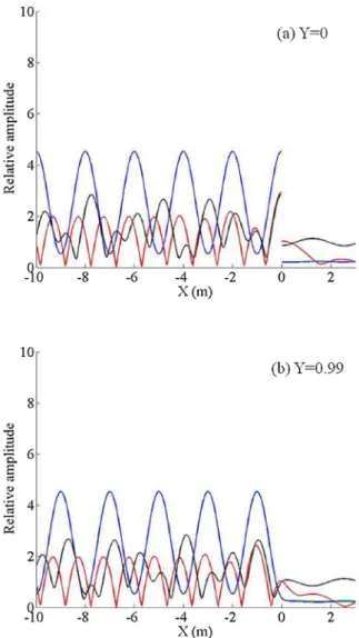
since there is a smooth transition between an evanescent mode for mode 2 tending to zero (almost no decrease along x < 0), to a pro-pagating mode in a direction closed to normal with respect to the in-cident wave. In both two cases, we can observe huge oscillations forced by the reasoning wave conditions along the y-axis, due to the periodi-city of the breakwaters. All thefindings are also observed inFig. 6(a) for y = 0 and in FigFigure 6(b) for y = 0.99, near the boundary or axis of symmetry.
3.1.2. Vertical cylinder of circular section
For cylinders of circular section, boundaries are discretized into steps. For simplicity, the discretization length along x-axis is kept constant (see Fig. 7). Tests of convergence with respect to both the number of modes nmodesand the number of steps of discretization nsteps
of the cylinders are presented inFigs. 8–Figure 10. In the configuration presented here water depth is h = 1 m, the cylinder diameter D = 0.5 m, the domain width is Lb= 1.35 m, the domains width
cor-responds to half a basin (of vertical walls) width Lb, or to a periodic raw
of cylinders along y-axis of periodicity 2Lb. Frequency is f = 1 Hz, the Fig. 3. Sketch of half of the breakwater.
Fig. 4. Reflection coefficient versus kb: (—) first mode (n = 0); ( ) second mode (n = 1); ( ) third mode (n = 2); ( ) fourth mode (n = 3); relative re-flected energy flux versus kb: (-.-) first mode (n = 0); (- -) total energy. Vertical dashed lines correspond to the locations of the frequency cases presented in
threefirst modes are propagative in this configuration. A colourplot of the surface wave amplitudefield is given inFig. 8. We can observe a rapid convergence of the wave behaviour, especially in the farfield. This rapid convergence is also observed inFig. 9through the behaviour of the wave amplitude along two different transects, (a) at y = 0 which corresponds to the axis of the vertical cylinder, and (b) at y = 0.6 which corresponds to a section next to the cylinder position. We can observe that even if the discretization of the cylinder is rough, farfield effects are already well reproduced for nsteps= 5. In order to better quantify
this convergence, the relative error of the wave amplitude in the near field and of the reflection coefficient for the three propagating modes, representing the far field behaviour, are presented respectively in Fig. 10a and b. We define here the relative error ERiof a quantityφiby
= φ −φ φ ERi | n i|
n (23)
where index i corresponds to a given number of steps nstepsfor the
calculation, and n to the maximum number of steps considered for the test, here, n = 10. We can observe that a relative good convergence is reached for nsteps= 5, with globally smaller relative errors for the
re-flection coefficients. Such a rapid convergence for the far field was also observed and discussed in [17] for wave propagating over varying bottoms discretized into successive steps, even if perfect continuity for the horizontal velocity is hardly reached at the steps for steep slopes even when increasing the number of evanescent modes. In the present case, modes n, n > 1 are either propagating or evanescent, con-vergence is rapidly reached as shown inFigs. 8andFigure 9. In fact practically a compromise has to be done between the precision of the results and the size of the system to be solved numerically. For farfield
calculations as the reflected coefficient, we verify that a good con-vergence of the results is reached at a given nmodesand nsteps.
3.2. Periodic cylinder arrays
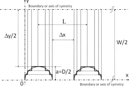
In this section, examples are given for arrangements of cylinders of circular section as already studied in previous works. We consider hereafter the cases of sparse (a/L≪ 1) or dense (a/L of order 1) arrays, where a = D/2 and L are the cylinder radius and the distance between the centres of adjacent rows of cylinders, respectively (seeFig. 11). Also, W is the width of the channel (transverse periodicity of the ar-rangement). Reflection coefficient is discussed versus frequency or di-mensionless wavenumber.
3.2.1. Sparse array
In this first section, we consider the case of sparse cylinders as studied by Li and Mei [23]. In their study, only thefirst mode is pro-pagative in the range of frequency considered. We extend here the study to higher frequencies, for which scattering is observed not only for the reflected wave along the x-axis, direction of propagation of the incident wave, but also for scattered waves (oblique waves). We will consider here the same configuration as Fig. 9 of [23], where they compare results from their asymptotic solution with those from afinite element method, for a/L = 0.10, L/W = 1, N = 10, a, L, W and (2N + 1) being the cylinder radius, the distance between two successive cylinders along the x-axis, the channel width and the number of cy-linders along x-axis, respectively. A sketch of the configuration is shown inFig. 11. Results with the present method concerning the reflected wave are calculated for N = 5 (a row of 11 cylinders) with a
discretization step nsteps= 5 for each of the cylinders. Results
con-cerning the reflection coefficient corresponding to each of the propa-gating modes are presented inFig. 12for a truncation of the series at either the fourth orfifth mode. For the higher values of the frequency range (kL/π = 5), three modes are propagative. Convergence is more rapid at lower frequencies, for which only one mode is propagative. We can observe that convergence is globally reached for P = 4 (five modes)
on the range of frequency considered. We can notice that since the channel width W = L, only thefirst mode (n = 0) is propagative for kL <π. As in [23], we can observe for mode 1 a strong reflection near kL =π and kL = 2π. These two peaks correspond to respectively 1st and 2nd order Bragg resonances which correspond to resonant wave -medium interactions when the spatial periodicity of the -medium is half the wave wavelength atfirst order (here kL = π), or a multiple of half the wave wavelength for higher orders (here kL = pπ, p > 1). Let us note that these peaks are slightly shifted towards low wavenumbers, due to thefinite size of the cylinders (see also [23]). High values of the reflection coefficient above one is observed for mode 2 and for mode 3, for kL = 2π and kL = 4π respectively. As for the case of the break-waters, they correspond to transverse wave resonances due to the periodicity of the array of cylinders along y-axis, since the width W = L in the present case. Periodic shorter and smaller oscillations with re-spect to kL =π are also observed which correspond to the finite length of the row of cylinders along x-axis. Indeed, if we consider the length of the patch of cylinders, Lrow= (2N + 1)L, conditions of resonance are
kL/π = p/(2N + 1), p > 1.
For kL/π ⩽ 1, 2N + 1 values of extrema are then found. Let us note that this number more or less corresponds to Fig. 9 of [23], which however refers to 21 cylinders (N = 11) instead of 11 (N = 5) in the present case. Concerning modes 2 and 3, high reflection coefficients (amplitude with respect to the amplitude of the incoming mode 1, see Eq.(18)) are also observed. They are also due to resonance conditions for these modes. Since these modes are generated within the array of cylinders, resonance conditions, which lead to a strong reflection, correspond to opposite phase conditions at successive cylinders, for kxn,
the component of knalong x-axis. kxnL = (2p + 1)π/2, p > 1 where
n = 1 for mode 2 and n = 2 for mode 3. Reflection for modes 2 and 3 are presented inFig. 13a and b respectively. Total energy reflected and energy reflection due to modes 1–3 (n = 0–2) are also presented. We can observe that the main energy reflected is due to these oblique modes at their resonance conditions. Near full wave reflection, espe-cially through mode 2, is observed for kx1L/π of about 1.5 (p = 1) and
kx1L/π of about 2.5 (p = 2). Let us note that the shift of the resonant
peak towards lower wavenumbers increases as the wavenumber in-creases, which corresponds to an increase of the relative size of the cylinders with respect to the wave wavelength. Contrary to those of the resonant peaks for modes 1 and 2, the shapes of the resonant peaks for mode 3 exhibit a more irregular shape at resonance. We can observe for instance a huge reflection coefficient for mode 2 just under kx2L/
π = 1.5, and a significant reflection for mode 1 above. The asymmetric shape of the reflection coefficient of the third mode near resonance may then be related to the evolution of the other modes near this value. We also observe inFig. 13b that a sudden drop of the reflection coefficient for the third mode occurs in the neighbourhood of kx2L/π = 1.5.
Ex-tensive numerical calculation has shown that this result is due to the convergence of the present method, which appears to become poor in the close vicinity of the above frequency, where the condition of the matrix system becomes near singular.
3.2.2. Dense array
We consider here the case of dense arrays of cylinders as considered in the framework of the thesis of [24] and presented in a two dimen-sional wave tank in [7]. In this 2D study, dense array of staggered circular cylinders is considered as a porous medium, with porosity enough to allow the wave to propagate through and to dissipate slowly. Effects of both porosity and specific surface are discussed in the above paper. We here only consider wave propagation across the dense array of cylinders, neglecting the damping effects. The aim is to discuss the wave properties in terms of its wavelength (or celerity) within the porous media through the calculation of the reflected coefficient. Be-cause of thefinite length of the porous medium, interference process leads to a oscillating behaviour of the reflection coefficient versus fre-quency, as shown in [7]. Since reflection was measured versus Fig. 6. Relative amplitude with respect to the incoming wave amplitude for ( )
kb− π =−0.1, ( ) kb − π =−10−8, ( ) kb− π = 10−8, (—) kb − π = 0.1 along the section, (a) y = 0; (b) y = 0.99.
frequency, ranging from shallow water to deep water conditions, a wide range of wave conditions were then considered on a large range of wavelengths. Other types of experiments carried out at resonance for a given wavelength can also be considered to characterize the wave wavelength, as done recently by Molin et al. [12]. In [7], the velocity potentials are calculated through integral matching by considering the whole arrays of cylinders as a porous medium. The dispersion relation is = ω S gk tanh(kh) 2 (24) where = + − S C γ γ 1 M(1 ) (25) where S is a dimensionless reactance and CMis an added mass
coeffi-cient, CM= 1 for a single cylinder. This coefficient is chosen as a
ad-justable coefficient in [7]. It is therefixed to CM= 0.29, in order tofit
the experimental oscillating behaviour of the reflected coefficient versus frequency. Wave dissipation is taken into account through a linear or quadratic decay of the wave amplitude across the porous medium. For a linear decay, the complex wave number kpwithin the
porous medium is of the formkp=k(1+ik/nw).nwcorresponds to an
attenuation rate per wavelength unit, it does not depend on frequency. The dispersion relation(24)is a simplified form of
= ω Z igk tanh(kh) 2 (26) proposed by Yu and Chwang [25], where Z = fR+ iS is the
di-mensionless impedance of the porous medium, fRbeing a dimensionless
resistance. In this latter formulation, wave decay is directly connected to the wave wavenumber through the complex dispersion relation. These different approaches are discussed in [7].
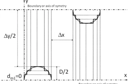
The array of cylinders considered in [7] consists of rows of cylinders with an angle ofπ/4 with the incoming wave direction. We here con-sider the case of cylinders of diameter D = 0.05 m, with 20 cylinders along axis. The distance between two successive cylinders along x-axis isΔx = 0.01 m, distance along y-axis is Δy = 0.064 m. This corre-sponds to a porous length Lp= 1.20 m, its porosityγ = 0.7. The water
depth h = 0.23 m. Taking advantage of the symmetry axes, the re-solution with the present model can be done between two lateral boundaries, as shown inFig. 14. Results in terms of reflection coeffi-cient versus frequency are presented inFig. 15a, considering either 4 or 5 modes (P = 3 or P = 4). Let us note that in the present configuration, only thefirst mode is propagative on the whole frequency range con-sidered. Cylinders are discretized into nsteps= 5. If we already observed
a good general trend for P = 2 (not shown), convergence is assumed to be reached for P = 4, as shown inFig. 15b, through analysis of the relative error for the reflection coefficient versus the number of modes at either f = 0.5 Hz (shallow water depth, kh = 0.50), f = 1.0 Hz (finite water depth, kh = 0.10), f = 1.5 Hz (finite water depth, kh = 2.14), f = 2.0 Hz (deep water, kh = 3.70). Both experimental results and the numerical results from Arnaud et al. [7] either taking into account dissipation withnw=25, as presented inFig. 4, bottom, of their paper, or neglecting dissipation (nw⟶∞) are also presented inFig. 15a.
The semi-empirical method of [7] based on afit of the added mass CM= 0.29 was found tofit correctly with the experiments on the whole
frequency range. In addition, we observe that neglecting dissipation does not affect the location of the minima of reflection for this weakly dissipative medium case. The location of the minima of reflection for
the present model sensibly fits those of [7] on the whole frequency range.
Neglecting dissipation, various formulations for the dispersion re-lation have been proposed (see [12] and references cited there). For vertical cylinders, the porous medium is considered as an anisotropic medium, derivations in [12] lead to the following dispersion relation:
⎜ ⎟ = ⎛ ⎝ ⎞ ⎠ ω S S gk tanh kh 2 (27) which tends to (26)in shallow water conditions. This formulation is found to provide a good agreement with sloshing test which allow determination of the frequency at resonance. In order to discuss the wave equivalent wavelength through the dense array of cylinders, re-flection coefficient versus the dimensionless frequency kLpis presented
in Fig. 16. Results of the present method are compared against pre-dictions based on the use of dispersion relation(24)with respectively CM= 0.29 and CM= 1, and the dispersion relation(27)with CM= 1.
Thefirst five modes (P = 4) are considered for the present calculation, nstep= 5 is used for the discretization of the cylinders.
For both the methods of [25,12] using CM= 1, which corresponds
to the added mass of a single cylinder, we can observe that the minima of reflection are significantly shifted toward lower frequencies. This shift, which is the higher for the method of [25], significates implicitly that the wave wavelenth (or its celerity) within the porous media is not accurately modelled, especially for the higher frequencies.
Other calculations with the present method where carried out with
rows of cylinders along the x-axis, but with both the same porosity and the same specific surface (same number and size of cylinders). Results are presented inFig. 17for either aligned or staggered cylinders. Cal-culations are done with either one mode (P = 0) orfive modes (P = 4). While considering only the first mode (P = 0), reflection coefficient does not depend on the array arrangement (aligned or staggered cy-linders). Physically, higher modes are to be considered. We can con-sider here that convergence is reached for P = 4 as shown inFig. 15. We can then observe a difference in the location of the successive minima or maxima of reflection coefficient, which means that the wave equivalent wavelength within the porous medium depends on the ar-rangement of the cylinders. For staggered cylinders, minima of reflec-tion are observed at lower frequency (higher wavelength) with respect to those for aligned cylinders. Arnaud et al. [7] had pointed out the influence of the porosity on the wave reflection, but had found that the specific surface did not play a significant role in the interference pro-cess, its role being essentially important on the wave damping. The cylinder array arrangement was the same in that work for the three cylinder diameters considered. We can deduce from the present results that the arrangement of the cylinders has a significant impact on the equivalent wave wavelength within the porous media, it plays in fact a role which can be compared to the tortuosity defined classically in mechanics for porousflows to characterize the permeability in addition to the porosity and the specific surface [26]. The tortuosityτ = L′/Lp
where L′ corresponds to the tortuous trajectory of the fluid within the porous medium. In the present case, the tortuosity is then higher for staggered cylinders than for aligned cylinders.
Fig. 9. Relative wave amplitude along a x-transec with respect to the incoming wave amplitude, influence of the number of modes and of the number of steps of discretization of the cylinder, ( ) nsteps= 5, nmodes= 5; ( ) nsteps= 10, nmodes= 5; ( ) nsteps= 5, nmodes= 10; (—) nsteps= 10, nmodes= 10; (a) y = 0, (b) y = 0.6; vertical lines indicate the cylinder position.
Fig. 10. Relative error (a) of the amplitudes, (b) of the reflection coefficients versus the number of steps nsteps. (a) (—*) x =−0.0135, y = 0; ( ) x = 0.5085, y = 0; ( ) x =−0.0135, y = 0.6; ( ) x = 0.5085, y = 0.6. (b) (—*) first mode; ( ) second mode; ( ) third mode.
4. Discussion and conclusion
Integral matching method is used for the numerical study of water wave scattering by arrays of surface-piercing structures. The method, already used for many years for rectangular breakwaters (see [3]), is here applied to various cases including sparse or dense surface-piercing structures with vertical walls. When applied to wave scattering by periodic arrays of cylinders, from long wave conditions (or narrow channels) to short waves (compared to the structure size or spacing), it is shown than far field effects as the reflection coefficient generally rapidly converge with both the number of the wave modes and the number of steps of discretization in the case of vertical structures with smooth contours. Convergence may however be checked carefully, especially when the matrix system becomes near singular as discussed at the end of Section3.2.1for resonance conditions for the third pro-pagating mode. For long waves across cylinders arrays, we observe huge reflections at Bragg resonance as already discussed by Li and Mei [23] in the incoming wave direction but also for other directions, ac-cording to resonance conditions for the oblique higher wave modes within the cylinders area. Resonance conditions also appear normally to the incoming wave direction when the channel width or the periodicity
of the structures in this direction is a multiple of half the wavelength. For such corresponding frequencies, huge oscillations may be observed in a frequency band covering both parts of this resonance condition. Under the critical frequency, this oscillation is due to the evanescent
Fig. 12. Reflection coefficient in the case of sparse array of 11 cylinders (a/ L = 0.10, L/W = 1) versus kL/π: (- -) first mode, P = 2 (3 modes); (—) first mode, P = 3 (4 modes); ( ) second mode, P = 2 (3 modes); ( ) second mode, P = 3 (4 modes); ( ) third mode, P = 2 (3 modes); ( ) third mode, P = 3 (4 modes).
Fig. 13. (a) Reflection versus kx1L/π: ( ) reflection coefficient for the second mode; ( ) total reflected energy; (—) reflected energy for the first mode; ( ) reflected energy for the second mode; ( ) reflected energy for the third mode. (b) Reflection versus kx2L/π: ( ) reflection coefficient for the third mode; ( ) total reflected energy; (—) reflected energy for the first mode; ( ) reflected energy for the second mode; ( ) reflected energy for the third mode. Fig. 11. Sketch of the aligned circular cylinders.
modes, and tends to diminish far from the structure. Over the critical frequency, this oscillation is due to the additive propagating mode above the resonant frequency and does not vanish far from the struc-ture. This is what we observed for the rectangular breakwater already
Fig. 14. Sketch of the staggered circular cylinders.
Fig. 16. Reflection coefficient versus dimensionless frequency, ( ) Molin et al. [12]; ( ) Yu and Chwang [25], CM= 1, without dissipation; (—) Arnaud et al. [7], CM= 0.29, without dissipation; ( ) present method, P = 4 (5 modes).
Fig. 17. Reflection coefficient versus dimensionless frequency, (—) staggered, one mode (P = 0); ( ) aligned, one mode (P = 0); ( ) staggered, three modes (P = 4); ( ) aligned, three modes (P = 4).
Fig. 15. (a) Reflection coefficient versus frequency, (—) Arnaud et al. [7], with linear dissipation (nw=25); ( ) Arnaud et al. [7], without dissipation (nw⟶∞); ( ) present method, P = 3 (4 modes); ( ) present method, P = 4 (5 modes); (*) experimental data from Arnaud et al. [7]. (b) Relative error versus the number of modes: (*) f = 0.5Hz; ( ) f = 1Hz; ( ) f = 1.5Hz; ( ) f = 2Hz.
studied by Dalrymple and Martin [3] for thefirst mode. When con-sidering dense cylinder arrays, the structure can be considered as a porous medium (see [7]). In this case, the obtained results fit with experiments of [7] in terms of the oscillatory behaviour of the reflection coefficient versus frequency. In the present method, the potential is calculated at the scale of the cylinders, contrary to the methods used in [25,12] or [7] for which the porous medium is considered as an homogeneous medium at the scale of the wave, for which a wave wa-venumber can be defined by a dispersion relation. Calculation of the reflection coefficient for another cylinder arrangement gives slightly different results, with a shift of minima and maxima of reflection versus frequency. In the experiments of [7], three different porous media of identical porosity and different specific surface were considered. The cylinders arrangement was the same for the three media. Since the dispersion relation with the same fitted added mass coefficient CM= 0.29 for the whole cases was found to allow a goodfit between
model and experiments, Arnaud et al. [7] concluded that this coeffi-cient did not depend on the specific surface for a given porosity and shape of the cylinders array. We observed here that this added mass however depends on the cylinders arrangement. This shows that a third permeability parameter, the tortuosity, has to be defined to fully define the porous properties in terms of permeability. The right equivalent wavelength within the porous medium has to take into account the cylinders arrangement. The present study focused on particular cases as described in the literature but is also applicable to structures with vertical walls of any shape in the horizontal plane. More complex structure geometries can then be considered, either for coastal or off-shore purposes.
As mentioned in the introduction, dissipation effects may become significant for rather dense arrays of cylinders. In the present study, the theoretical model assumed perfect fluid and focused on wave scat-tering, neglecting damping effects. If one considers that dissipation remains small enough, dissipation effects can be taken into account through an exponentially decrease of the wave amplitude within the dense array of emerging vertical cylinders. Such a approach was used in [7] for the model used in their study, it is in progress for the model used in the present study.
Acknowledgements
Financial support from the University of Toulon for the visit of K. Belibassakis as invited Professor is acknowledged.
References
[1] H. Kagemoto, D.K.P. Yue, Interactions among multiple three-dimensional bodies in water waves: an exact algebraic method, J. Fluid Mech. 166 (1986) 189–209. [2] C.O.G. Ohl, R.E. Taylor, P.H. Taylor, A.G.L. Borthwick, Water wave diffraction by a
cylinder array, J. Fluid Mech. 442 (2011) 1–32.
[3] R. Dalrymple, Martin, Wave diffraction through offshore breakwaters, J. Waterway Port Coast. Ocean Eng. 116 (6) (1990) 727–741.
[4] G. Abul-Azm, A.N. Williams, Oblique wave diffraction by segmented offshore breakwaters, Ocean Eng. 24 (1) (1997) 63–82.
[5] C.C. Mei, P. Liu, Waves of intermediate length through an array of vertical cylinder, Environ. Fluid Mech. 14 (2014) 235–261.
[6] C.C. Mei, I.C. Chan, P. Liu, Z. Huang, W. Zhang, Long waves through emergent coastal vegetation, J. Fluid Mech. 687 (2011) 461–491.
[7] G. Arnaud, V. Rey, J. Touboul, D. Sous, B. Molin, F. Gouaud, Wave propagation through dense vertical cylinder arrays: interference process and specific surface effects on damping, Appl. Ocean Res. 65 (2017) 229–237.
[8] C.C. Mei, The Applied Dynamics of Ocean Surface Waves, World Scientific, 1989. [9] M. Simon, Multiple scattering in arrays of axisymmetric wave-energy devices. Part
1. A matrix method using a plane-wave approximation, J. Fluid Mech. 120 (1982) 1–25.
[10] D.A.G. Walker, R.E. Taylor, Wave diffraction from linear arrays of cylinders, Ocean Eng. 32 (2005) 2053–2078.
[11] C.M. Linton, D.V. Evans, The interaction of waves with arrays of vertical circular cylinders, J. Fluid Mech. 215 (1990) 549–569.
[12] B. Molin, F. Remy, G. Arnaud, V. Rey, J. Touboul, D. Sous, On the dispersion equation for linear waves traveling through or over dense arrays of vertical cylin-ders, Appl. Ocean Res. 61 (2016) 148–155.
[13] Horikawa, Nearshore Dynamics and Coastal Processes, Tokyo Press, 1988. [14] D.V. Evans, C.M. Linton, Trapped modes in open channels, J. Fluid Mech. 225
(1991) 153–175.
[15] J.N. Newman, Trapped-wave modes of bodies in channels, J. Fluid Mech. 812 (2017) 178–198.
[16] E. Guazzelli, V. Rey, M. Belzons, Higher-order Bragg reflection of gravity surface waves by periodic beds, J. Fluid Mech. 245 (1992) 301.
[17] V. Rey, Propagation and local behavior of normally incident gravity waves over varying topography, Eur. J. Mech. B Fluids 11 (2) (1992) 213–232.
[18] G. Athanassoulis, K. Belibassakis, A consistent coupled-mode theory for the pro-pagation of small-amplitude water waves over variable bathymetry regions, J. Fluid Mech. 389 (1999) 275–301.
[19] V. Rey, A note on the scattering of obliquely incident gravity waves by cylindrical obstacles in waters offinite depth, Eur. J. Mech. B Fluids 14 (1) (1995) 207–216. [20] V. Rey, V.J. Touboul, Forces and moment on a horizontal plate due to regular and
irregular waves in the presence of current, Appl. Ocean Res. 33 (2011) 88–99. [21] K. Belibassakis, V. Tsoukala, V. Katsardi, Three-dimensional wave diffraction in the
vicinity of openings in coastal structures, Appl. Ocean Res. 45 (2014) 40–54. [22] D.T. Zhu, Y.F. Xi, Hydrodynamic characteristics of offshore and pile breakwaters,
Ocean Eng. 104 (2005) 257–265.
[23] Y. Li, C.C. Mei, Bragg scattering by a line array of small cylinders in a waveguide. Part 1. Linear aspects, J. Fluid Mech. 583 (2007) 161–187.
[24] G. Arnaud, Houle à la côte: Propagation, impacts et ouvrages innovants (Ph.D. thesis), University of Toulon, Toulon, 2016.
[25] X. Yu, A. Chwang, Wave motion through porous structures, J. Eng. Mech. 120 (1994) 989–1008.
[26] E. Guyon, J.P. Hulin, L. Petit, C. Mitescu, Physical Hydrodynamics, Oxford University Press, 2015.