HAL Id: hal-01709193
https://hal.archives-ouvertes.fr/hal-01709193
Submitted on 14 Feb 2018HAL is a multi-disciplinary open access archive for the deposit and dissemination of sci-entific research documents, whether they are pub-lished or not. The documents may come from teaching and research institutions in France or abroad, or from public or private research centers.
L’archive ouverte pluridisciplinaire HAL, est destinée au dépôt et à la diffusion de documents scientifiques de niveau recherche, publiés ou non, émanant des établissements d’enseignement et de recherche français ou étrangers, des laboratoires publics ou privés.
Testing Prototypes and Final User Interfaces Through
an Ontological Perspective for Behavior-Driven
Development
Thiago Rocha Silva, Jean-Luc Hak, Marco Winckler
To cite this version:
Thiago Rocha Silva, Jean-Luc Hak, Marco Winckler. Testing Prototypes and Final User Interfaces Through an Ontological Perspective for Behavior-Driven Development. 6th International Conference on Human-Centered Software Engineering (HCSE 2016), Aug 2016, Stockholm, Sweden. pp. 86-107. �hal-01709193�
O
pen
A
rchive
T
OULOUSE
A
rchive
O
uverte (
OATAO
)
OATAO is an open access repository that collects the work of Toulouse researchers and makes it freely available over the web where possible.This is an author-deposited version published in : http://oatao.univ-toulouse.fr/
Eprints ID : 18842
The contribution was presented at HCSE 2016:
http://www.hcse-hessd.org/
To cite this version : Rocha Silva, Thiago and Hak, Jean-Luc and Winckler, Marco Antonio Testing Prototypes and Final User Interfaces Through an
Ontological Perspective for Behavior-Driven Development. (2016) In: 6th
International Conference on Human-Centered Software Engineering (HCSE 2016), 29 August 2016 - 31 August 2016 (Stockholm, Sweden).
Any correspondence concerning this service should be sent to the repository administrator: [email protected]
Testing Prototypes and Final User Interfaces Through
an Ontological Perspective for Behavior-Driven
Development
Thiago Rocha Silva(✉), Jean-Luc Hak, and Marco Winckler
ICS-IRIT, Université Paul Sabatier, Toulouse, France {rocha,jean-luc.hak,winckler}@irit.fr
Abstract. In a user-centered development process, prototypes evolve in iterative cycles until they meet users’ requirements and then become the final product. Every cycle gives the opportunity to revise the design and to introduce new requirements which might affect the specification of artifacts that have been set in former development phases. Testing the consistency of multiple artifacts used to develop interactive systems every time that a new requirement is introduced is a cumbersome activity, especially if it is done manually. This paper proposes an approach based on Behavior-Driven Development (BDD) to support the auto‐ mated assessment of artifacts along the development process of interactive systems. The paper uses an ontology for specifying tests that can run over multiple artifacts sharing similar concepts. A case study testing Prototypes and Final User Interfaces is presented to demonstrate the feasibility of this approach in early phases of the design process, providing a continuous quality assurance of require‐ ments, and helping clients and development teams to identify potential problems and inconsistencies before commitments with software implementation.
Keywords: Automated requirements checking · Behavior-Driven Development · Ontological modeling · Prototyping · Multi-artifact testing
1
Introduction
It is a common understanding that in user-centered design (UCD) processes, users’ requirements and needs are not always identified at once but they are rather revised/ tuned and incrementally introduced along the multiple iterations through the use of Prototypes. When requirements are updated and/or new ones are introduced, the devel‐ opment team must cross-check their consistency with artifacts set in former development phases. Testing and tracing requirements during the development of interactive system is a daunting task specially because the development team has to deal with many cycles of iterations, multiple artifacts (such as Task Models, Prototypes, User Stories, Scenarios, etc.), and many design options for Prototypes that evolve until they reach the status of Final Product.
The traceability of artifacts can be said as vertical and horizontal [19]. Vertical traceability describes the relationship between artifacts that can be derived from each
other, for example from customer requirements to acceptance test cases. Horizontal traceability refers to the evolution of the same artifact. The artifacts traceability problem has been studied by several authors and a wide set of commercial tools have been devel‐ oped to address this problem in various approaches [16]. Nonetheless, solutions to promote vertical traceability of artifacts are not allowing to effectively testing them against requirements specifications.
Testing the consistency of artifacts with respect to user requirements is crucial for the quality of the software under development. Moreover, the sooner the teams pay attention to test their software components and especially their requirements specifica‐ tions, more effective will be the results towards a quality assurance of the product. As argued by Lindstrom [21], failing to trace tests to requirements is one of the five most effective ways to destroy a project. Nonetheless, according to Uusitalo et al. [17], trace‐ ability between requirements and tests used to assess the implementation are rarely maintained in practice not only because of stringent enforcement of schedules and budgets, but also because it is difficult to update traces when requirements change and due to the difficulties to conduct testing processes manually.
In this context, Behavior Driven Development (BDD) [10] has aroused interest from both academic and industrial community in the last years. Supported by a wide devel‐ opment philosophy that includes Acceptance Test-Driven Development (ATDD) [22] and Specification by Example [23], BDD drives development teams to a requirements specification based on User Stories [4] in a comprehensive natural language format. This format allows specifying executable requirements, conducting to a “live” documentation and making easier for clients to set their final acceptance tests. It guides the system development and brings the opportunity to test Scenarios directly in the User Interface with the aid of external frameworks for different platforms. However, this technique is currently limited to test requirements against a fully implemented user interface using specialized robots like Selenium WebDriver. Besides that, specifications using only Scenarios are not self-sufficient to provide a concrete perception of the system to the users and, at the same time, allow an overall description of the system in terms of tasks that may be accomplished. This is particularly true in early phases of the development process when the Prototypes are rudimental samples of interactive system.
In this paper we explore the use of BDD techniques for supporting automation of user requirements testing of artifacts produced throughout the development process of interactive systems. Our ultimate goal is to test multiple artifacts throughout the devel‐ opment process looking for vertical and bidirectional traceability of functional require‐ ments. To achieve this goal, a formal ontology model is provided to describe concepts used by platforms, models and artifacts that compose the design of interactive systems, allowing a wide description of UI elements (and its behaviors) to support testing activ‐ ities. Whilst the approach is aimed at being generic to many types of artifacts, in this paper we have focused on Prototypes and Final UIs. In the following sections we present the conceptual background, an overview of the underlying process for using the approach and a case study that demonstrate its feasibility. Lately, we discuss related works and the next steps for this research.
2
Conceptual Background
Hereafter is a summary of the basic concepts to explain how the approach works.
2.1 User Stories and Scenarios
A large set of requirements can be expressed as stories told by the user. Nonetheless, the term User Story might have diverse meaning in the literature. In the Human-Computer Interaction (HCI) field, a User Story refers to a description of users’ activities and jobs collected during meetings, which is close to the concept of Scenarios given by Rosson and Carroll [8]. Users and other stakeholders typically talk about their business process emphasizing the flow of activities they need to accomplish. These stories are captured in requirements meetings and are the main input to formalize a requirements artifact. These meetings work mainly like brainstorm sessions and include ideally several stakeholders addressing needs concerning features that may be developed. As stated by Lewis & Rieman, “…scenarios forced us to get specific about our design, […] to consider how the various features of the system would work together to accomplish real work…” [9]. For Santoro [7], Scenarios provide informal descriptions of a specific use in a specific context of application, so a Scenario might be viewed as an instance of a use case. An identification of meaningful Scenarios allows designers to get a descrip‐ tion of most of the activities that should be considered in a task model. Given task models have already been developed, Scenarios can also be extracted from them to provide executable and possible paths in the system.
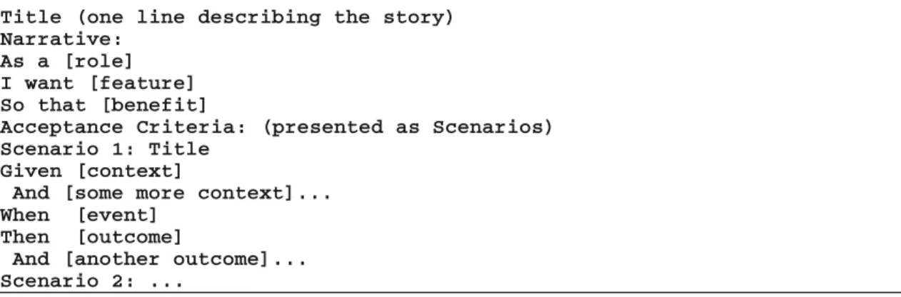
In the Software Engineering (SE), the term User Stories is typically used to describe requirements in agile projects [4]. They are formatted to fulfil two main goals: (i) assure testability and non-ambiguous descriptions and (ii) provide reuse of business Scenarios. Figure 1 presents a template for formalizing User Stories.
Fig. 1. Template for specifying User Stories as defined by North [3] and Cohn [4] A User Story is thus described with a Title, a Narrative and a set of Scenarios repre‐ senting Acceptance Criteria. The Title provides a general description of the story. The Narrative describes the referred feature in terms of role that will benefit from the feature, the feature itself, and the benefit it will bring to the business. The Acceptance Criteria are defined through a set of Scenarios, each one with a Title and three main clauses:
“Given” to provide the context in which the Scenario will be actioned, “When” to describe events that will trigger the Scenario and “Then” to present outcomes that might be checked to verify the proper behavior of the system. Each one of these clauses can include an “And” statement to provide multiple contexts, events and/or outcomes. Each statement in this representation is called Step.
In the Behavior-Driven Development (BDD) [10], the user point of view about the system is captured by User Stories described according to the template shown in Fig. 1. The BDD approach assumes that clients and teams can communicate using a semi-structured natural language description, in a non-ambiguous way (because it is supported by test cases).
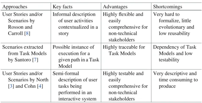
In some extension, all approaches agree on that User Stories and Scenarios must provide a step-by-step description of tasks being performed by users using a given system. Nonetheless, there are some differences as illustrated by Table 1. This analysis gives us the opportunity to establish a correlation between requirements identified in User Stories, their representation in terms of tasks and the extracted Scenarios in both UCD and SE approaches. We can notice that the main difference lies in the degree of formality and their possible value to support automated test. Another remark we can make is about the type of tasks mapped to Scenarios in SE. As SE consider only tasks being performed by users when using an interactive system, User Stories in this context address only Scenarios extracted from Interaction Tasks in Task Models; Cognitive Tasks, for example, are not mapped to be SE Scenarios because they cannot be performed in the system.
Table 1. Approaches for describing User Stories and Scenarios Approaches Key facts Advantages Shortcomings User Stories and/or
Scenarios by Rosson and Carroll [8] Informal description of user activities contextualized in a story
Highly flexible and easily comprehensive for non-technical stakeholders Very hard to formalize, little evolutionary and low reusability Scenarios extracted
from Task Models by Santoro [7]
Possible instance of execution for a given path in a Task Model
Highly traceable for Task Models
Dependency of Task Models and low testability User Stories and/or
Scenarios by North [3] and Cohn [4] Semi-formal description of user tasks being performed in an interactive system
Highly testable and easily
comprehensive for non-technical stakeholders
Very descriptive and time consuming to produce
2.2 Acceptance Testing of Functional Requirements
In this paper, we are interested in testing functional requirements that users raise through the means of User Stories and Scenarios. In Software Engineering, the testing activity covers several levels of abstraction, from low level of tests such as Unit and Integration
Testing to high level ones such as System and Acceptance Testing [20]. Low level tests are focused on the quality of the code which we call White Box testing approach. On the other hand, high level tests are more interested in the quality of the final product as a whole which we call Black Box testing approach. Tests can also be focused on specific aspects of the system such as Functional, Usability, Scalability or Performance aspects. Functional Testing identifies situations that should be tested to assure the correct working of the system under development in accordance with the requirements previ‐ ously specified. The Acceptance testing are tests made under the client/user point of view to validate the right behavior of the system. For that clients might be able to run their business workflows and to check if the system behaves in an appropriate manner. Several techniques are employed to conduct functional testing such as Boundary Value Analysis, Equivalence Class Testing, Decision Table Base Testing, etc. [20]. These techniques support the development of test cases that might be specified to validate the right implementation of the requirements.
The big challenge is that requirements are dispersed in multiple artifacts that describe them in different levels of abstraction. Thus, tests should run not only in the final product, but also in the whole set of artifacts to assure that they represent the same information in a non-ambiguous way and in accordance with the whole requirements chain. More‐ over, testing should be performed along the development process as clients and users introduce new demands or modify the existing ones all along the iterations. Regression Testing is crucial to assure that the system remains behaving properly and in accordance with the new requirements. However, manual Regression Tests are extremely time consuming and highly error-prone. Therefore, automated tests are a key factor to support testing in an ever-changing environment, allowing a secure check of requirements and promoting a high availability of testing.
2.3 Computational Ontologies
According to Guarino et al. [11], computational ontologies are a mean to formally model the structure of a system, i.e., the relevant entities and relations that emerge from its observation, and which are useful to our purposes. Computational ontologies come to play in this work as a mean to formalize the vocabulary and the concepts used in User Stories, Scenarios and other artifacts during the development process of interactive systems. Without a common agreement on the concepts and terms used it will be difficult to support traceability of user requirements across many artifacts. Nowadays, some approaches have tried to define languages or at least a common vocabulary for specifying UIs in interactive systems. Despite the fact there is no such a standard, a few ontologies are worthy of mention, including DOLPHIN [12], UsiXML [13] and W3C MBUI Glos‐ sary [14]. DOLPHIN [12] is a reference framework that formalizes concepts around task models and in particular provides a mean to compare task model notations. UsiXML (USer Interface eXtensible Markup Language) [13] is a XML-compliant markup language that describes the UI for multiple contexts of use such as Character User Inter‐ faces (CUIs) or Graphical User Interfaces (GUIs). UsiXML consists of a User Interface Description Language (UIDL) that is a declarative language capturing the essence of what a UI is or should be independently of physical characteristics. UsiXML describes
at a high level of abstraction the constituting elements of the UI of an application: widgets, controls, containers, modalities and interaction techniques. More recently, W3C has published a glossary of recurrent terms in the Model-based User Interface domain (MBUI) [14]. It was intended to capture a common, coherent terminology for specifications and to provide a concise reference of domain terms for the interested audience. The authors’ initial focus was on task models, UI components and integrity constraints at a level of abstraction independent of the choice of devices to implement the models.
3
A New Approach for Multi-artifact Testing
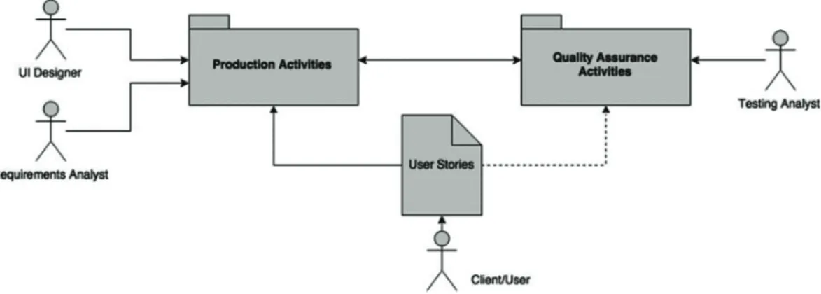
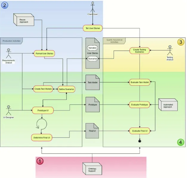
The approach relies on the premise that user requirements expressed by the means of User Stories and Scenarios can be specified using a standard user interface ontology which will allow testing automation against multiple artifacts through the development process of interactive systems. To explain how this could be, two figures (Figs. 2 and 3) are presented hereafter. Figure 2 shows how User Stories support both Production Activ‐ ities and Quality Assurance Activities. Client, Users and Stakeholders are the main source of User Stories that will be consumed by Requirements Analysts and User Inter‐ face (UI) designers in Production Activities and by Testing Analysts who are in charge of building test cases and assessing artifacts in Quality Assurance Activities. The Fig. 3
provides a workflow view of activities that have been grouped in Fig. 2.
Fig. 2. Overview of the Requirements Model
The operationalization of the approach is made up in four main steps that are pinpointed by numbers as follows: (1) definition of the ontology, (2) writing testable requirements, (3) adding test cases, and (4) testing Prototypes and other artifacts. These steps are described herein. To illustrate the operationalization of each step, we have proposed a case study in the flight tickets e-commerce domain in a traditional airline company, showing how the approach can support the testing of Prototypes and Final UIs. This case was chosen because it is easily comprehensible and we believe it repre‐ sents a common activity for the most part of readers. For the study, we have selected the American Airlines (AA) case to show these concepts. The AA model has been arbi‐ trarily chosen to conduct this work. However, as we know, the core of business models
for this kind of e-commerce is the same for all companies, so any other else could have been chosen instead.
The online booking process of flight tickets is basically divided in 3 main sub processes: searches of flights based on a provided set of data, the selection of the desired flight(s) in a list of flights resultant from the search, and finally providing passengers and payment data to conclude the booking. We have selected the two first processes for this study as they are the most interactive ones and represent the main source of cognitive efforts from users and designers. The third sub process is basically a data providing in forms so it is not so relevant to demonstrate the concepts presented in the paper, even though the whole process can be supported by this approach.
3.1 Step 1: Definition of the Ontology
The proposed ontology is largely inspired from existing languages and vocabularies already described in the Subsect. 2.3, but to make it operational we have created an OWL (W3C Web Ontology Language) specification covering concepts related to graphical
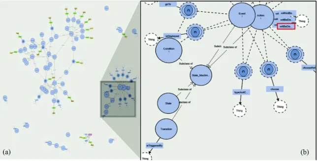
components (presentation and behavior) used to build Web and Mobile applications. Figure 4 presents a general view of the ontology structure. We started modeling concepts describing the structure of User Stories, Tasks and Scenarios. Following this, we have modeled the most common Interaction Elements used to build Prototypes and Final User Interfaces (FUIs) in the Web and Mobile environments. The dialog component that allows us to add dynamic behavior to Prototypes and navigation to FUIs was modeled as a State Machine (highlighted in the Fig. 4b). In this level, a Scenario that runs on a given interface is represented as a Transition in the machine, while the interface itself and the one resultant of the action were represented as States. Scenarios in the Transition state have always at least one or more Conditions (represented by the “Given” clause), one or more Events (represented by the “When” clause), and one or more Actions (represented by the “Then” clause).
Fig. 4. Ontology representation: (a) Overall View, (b) State Machine Concepts
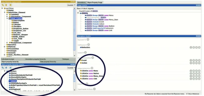
Figure 5 provides an example on how behavior specification is defined in the ontology. In the example, the behavior “clickOn” (see bottom-left side of the figure) has been associated to the Interaction Elements “Button”, “Menu_Item”, “Menu” and “Link” to express that these ones are the elements that would be able to answer this behavior when it is triggered. The ontology also specify that the behavior “ClickOn” is triggered by objects Action (“Then” clause) and Event (“When” clause).
Figure 6 shows how a Behavioral Property (behavior of graphical components) is mapped to Interaction Elements (presentation of graphical components) of the ontology. Each behavior is suitable to receive (or not) two parameters as in the example “I choose $elementName referring to $locatorParameters”, and to be triggered by the clauses “Given”, “When” and/or “Then”. In the example, whilst the first parameter is associated to a data for testing, the second parameter refers to the Interaction Element supported by this behavior: “Radio Button”, “CheckBox”, “Calendar” or “Link”. The ontological model describes only behaviors that report Steps performing common actions directly in the User Interface through Interaction Elements. We call it Common Steps (see Sect. 4.2).
This is a powerful resource because it allows us to keep the ontological model domain-free, which means they are not subject to particular business characteristics in the User Stories, instigating the reuse of Steps in multiple Scenarios. Specific business behaviors should be specified only for the systems they make reference, not affecting the whole ontology.
Fig. 6. Behaviors being mapped to UI Elements
Technically and with this structure, the current version of the ontology bears an amount of 422 axioms, being 276 logical axioms, 56 classes, 33 object properties, 17 data properties and 3 individuals.
3.2 Step 2: Writing Testable Requirements
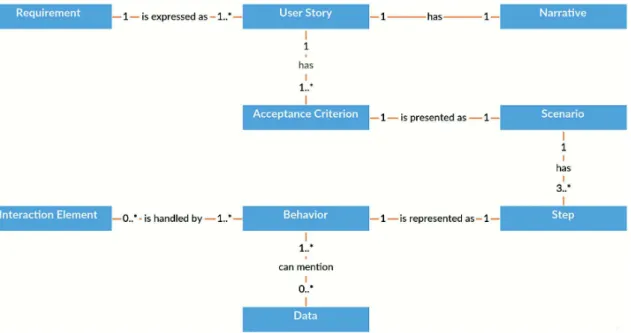
The approach is focused on functional requirements. A functional requirement defines statements of services that the system should provide, how the system should react to particular inputs and how the system should behave in particular situations. To assure that the system behaves properly, requirements should be expressed in a testable way. Figure 7 presents the conceptual model that explains how testable requirements are formalized in the approach. A requirement is expressed as a set of User Stories (US) as in the template proposed by North [3] and Cohn [4]. User Stories are composed by a Narrative and a set of Acceptance Criteria. Acceptance Criteria are presented as
Scenarios and these last ones are composed by at least three main Steps (“Given”, “When” and “Then”) that represent Behaviors which the system can answer. Behaviors handle actions on Interaction Elements in the User Interface (UI) and can also mention examples of data that are suitable to test them. Notice that these concepts are part of the ontology shown in Sect. 3.1.
Fig. 7. Conceptual Model for testable requirements
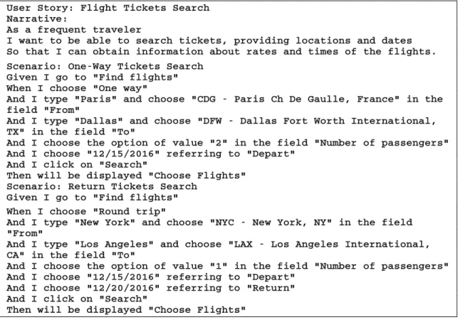
Hereafter, we present two User Stories with their respective Scenarios to describe and test the features of our case study. Figure 8 presents the User Story for searching flights in which the user should provide at least: a type of ticket he wants (one-way or round trip), the airport he wants to depart and arrive, the number of passengers, and finally the date of depart and return. In the first Scenario (“One-Way Tickets Search”), it is presented a typical search of tickets concerning a one-way trip from Paris to Dallas for 2 passengers on 12/15/2016. According to the business rule, the expected result for this search is a new screen presenting the title “Choose Flights”, in which the user might select the desired flight in a list of flights matching his search. The second Scenario (“Return Tickets Search”) simulates a round trip from New York to Los Angeles for only 1 passenger, departing on 12/15/2016 and returning on 12/20/2016. For this case, the same behavior is expected from the system, i.e., a new screen presenting the title “Choose Flights”, in which the user might select the desired flight in a list of flights matching his new search.
The User Story that selects the desired flight(s) is given in Fig. 9. The Scenario “Select a diurnal flight”, using the Scenario “One-Way Tickets Search” already executed, simulates the selection in the list of available flights, a couple of diurnal flights, the AA6557 and the AA51. For this case, the behavior expected from the system is the presentation of a new screen with the “Optional log in” message, indicating the user is able to login in order to proceed to the booking, filling the passengers and payment data.
Fig. 9. User Story for Select the desired flight formatted for the testing template.
3.3 Step 3: Adding Test Cases
Test Cases are represented as Testing Scenarios that specify potential error situations related to the Scenarios already defined to set Requirements. Testing Scenarios are the responsible component to describe the situations in which the system should be verified, covering as deeply as possible the largest set of features. Thereby, Scenarios and Testing Scenarios compose the User Stories, providing in the same artifact, descriptions of functionalities as well as the potential tests to verify the correct implementation of the requirements. As we have leading with functional testing in the acceptance level, the Black Box approach is used to check expected outcomes when predefined inputs are provided to the system. Figure 10 shows the Scenarios “Search for flights with more
than one year in advance” and “Search for a return flight before a departure flight” that will be added to the User Story “Flight Ticket Search”. They present specific business rules (and their tests) in the flight-booking domain. The expected outcome in both cases is the impossibility to search flights.
Fig. 10. Two Scenarios added to the User Story for Flight Ticket Search.
3.4 Step 4: Testing Prototypes and Other Artifacts
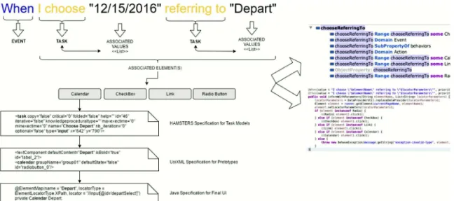
The execution of testing in Prototypes and other artifacts is exemplified in Fig. 11. The top part presents the Step of a Scenario describing the behavior “choose … referring to …”. In the example, a user chooses the date of depart “12/15/2016” on the field “Depart” in a form. This task is triggered when an event “When” occurs in the Scenario. This task is associated to values for date of depart (“12/15/2016”) and field (“Depart”), indicating a possible executable Scenario that can be extracted from that task. Following the ontology,
the behavior addressed by this task can be associated to multiple UI elements such as Radio Button, CheckBox, Link and Calendar components. The arrows in the right side of the figure indicate two implementations of this ontology, highlighting these associations. First in OWL version at the top and then converted in Java code in the bottom.
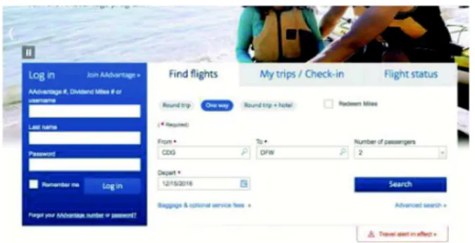
When the UI element Calendar is chosen, a locator is triggered to trace this element throughout the artifacts, thus allowing us to reach it for testing purposes. Figure 11 shows this trace being made through a HAMSTERS Specification for Task Models [24] (in the task “Choose Depart”), through a UsiXML Specification for Prototypes [13] (Calendar “Depart”), and finally through a Java Specification for Final UIs (@ElementMap “Depart” with the XPath reference “//input[@id=’departSelect’]” in a Calendar). For the purposes of the illustration when testing the User Story “Flight Tickets Search”, Fig. 12 presents the mapping of a Prototype and the Fig. 13 the mapping of a Final User Interface. Figures 14 and 15 present respectively the mapping of the Prototype and the Final UI for the User Story “Select the desired flight”.
Fig. 12. The “Find Flights” Prototype
Fig. 13. The “Find Flights” Final UI
Finally, the tests by a robot of the business rules “Search for flights with more than one year in advance” and “Search for a return flight before a departure flight” is presented in the Fig. 16. This behavior could have been implemented in several ways on the User Interface. The chosen solution by developers was to block in the calendar the inappro‐ priate dates according to the business rules.
Fig. 16. An attempt to select a return date before the departure date
4
Tool Support
This section presents a technical description about how tests are implemented in both Prototypes and Final UIs artifacts. For operationalizing the test we employ tools like Webdriver, JBehave and JUnit. Nonetheless, in order to integrate tests into development process of Prototypes, other tools also have been developed.
4.1 Testing in the Prototype Level
For the test in the Prototype Level, we have developed a prototyping environment named PANDA (Prototyping using Annotation and Decision Analysis) [25]. The development of a Prototype using this tool is made thanks to a toolbar containing widgets
Fig. 14. The “Choose Flights” Prototype
automatically generated from the OWL Ontology as described in the Subsect. 3.1. Once the toolbar is generated, the user can create his Prototype by placing widgets, whose properties are described in the ontology and presented in the edition area as illustrated in the Fig. 17. Using this technique allows to have a mapping between the elements described in the ontology (and thus, their properties and supported behavior) and each widgets of the Prototype.
Fig. 17. PANDA screenshot
A PANDA Prototype features a state machine where states of the system are popu‐ lated with the elements in the display when the state is active. By linking states with transitions, it is possible to specify the structure and the behavior of the Prototype. After having developed the Prototype, it is possible to replace a transition with a Scenario. Indeed, in the Fig. 17 we have a testing Scenario used as a transition in the state machine. This Scenario links together the state “Find Flight” represented by the rectangle with a grey header in the upper part of the Prototype with the state “Choose Flight” located in the lower part. The state “Find Flight” represents the initial condition (indicated by the “Given” clause) and the state “Choose Flight” represents the result of the Scenario execution (indicated by the “Then” clause).
PANDA supports Scenarios described in a text format which are imported in the edition area. When importing a Scenario, PANDA parses the different Steps and analyzes them by identifying the events, the tasks, the associated values and the targets of the task, as illustrated in the Fig. 11 in the Subsect. 3.4. This identification is done by splitting each line of the Scenario and identifying keywords like “Given” or “Then” and the quote character. Quoted segments are interpreted as values except for the last quoted element of each line, which is identified as the target of the task. Segments before the quoted elements are considered as actions related to the values read. Each line read is then registered as a Step of the Scenario. Figure 18 shows an example of a parsed Step. The value “Paris” is associated to the action “I type”, “CDG – Paris Ch De Gaulle, France” is associated to the action “choose” and “From” is associated to the locator “in the field”. Keywords are ignored except for the word « Given » and « Then » which introduce conditions and the final actions.
And I type "Paris" and choose "CDG - Paris Ch De Gaulle, France" in the field "From" Fig. 18. Example of a split Step during the parsing
Once the Scenario have been parsed and attached between an initial and a resultant state, it can be executed in order to find out if the Scenario is supported by the Prototype. This execution can be made step-by-step or with the whole set of Steps of the Scenario being executed at the same time. The system checks the state described in the Prototype and the properties defined in the ontology loaded, as well as if each Step is possible according to the task described in the Scenario. To do so, the system starts by making a mapping between the widgets of the Prototype and the target of the tasks during the execution, since Scenarios and states of the Prototype are independent. For the moment, this mapping is based on the name of the widget, but other mapping methods will be also considered. Then, for each Step whose target has been mapped, the system checks if each actions or properties matches with the properties of the widget which were defined in the ontology. As an example, in the Step “And I click on ‘Search’”, PANDA looks for any widget named “Search” in the initial state, and check if the description of the corresponding widget in the ontology support the behavior “ClickOn” (Fig. 19).
The results of the tests are displayed by a colored symbol next to each Step as shown in the Fig. 20. A red “X” represents failure, a green “V” represents success a black “?” represents an untested Step. There is currently no distinction between the different reasons of test failure (e.g. widget not found, property not supported, etc.). In our example, the button supports the event “#clickOn” which matches with the action “I click on” of the Scenario. However, none of the UI Elements (Calendar, CheckBox, Link or Radio Button) described in the ontology to support the behavior “chooseRefer‐ ringTo” was found.
Fig. 20. Example of results given during a Scenario testing
4.2 Testing in the Final UI Level
To test Final UI directly from User Stories, we use external frameworks (the so-called robots) to provide automated execution in the Final UI. Robots mimic user interactions with the Final UI by running Scenarios described in the User Stories. We use the robot Selenium WebDriver to run navigational behavior and JBehave and Demoiselle Behave to parse the Scenario script. Test results provided by the JUnit API indicate visually which tests passed and which ones failed and why. Execution reports of User Stories, Scenarios and Steps can be obtained by using the JBehave API.
Figure 21 presents the architectural model integrating tools and classes in the approach for testing the Final UI. The ontological model described in the Sect. 3.1 provides a pre-defined set of behaviors used at the Requirements Layer. Artifacts produced in Proto‐ typing and Task Layers are suitable to not only benefit from the ontology description to model better requirements, but also to contribute with the development of new User Stories. Pre-defined behaviors are mapped by the CommonSteps class that supports the development of specific behaviors not covered by the ontology, and subsequently mapped in the MySteps class. Both Steps are extracted from the User Stories that can be repre‐ sented in simple packages of text files. This structure composes the Requirements and Testing Layer. The Presentation Layer includes the MyPages class that describes the link between UI components defined in the ontology and the real UI components instantiated on the interface under testing. This link is crucial to allow the Selenium WebDriver robot and the other External Testing Frameworks to automatically execute the Scenarios in the right components on the UI. Finally, the MyTest class is a JUnit class responsible to trigger the tests, pointing which Scenarios should be executed and making the bridge between UI components in the Presentation Layer and executable behaviors in the Requirements and Testing Layer. Figure 22 shows the MyTest class automatically executing the “Return Tickets Search” Scenario presented in the case study.
Fig. 21. Architectural representation of automated testing in the Final UI
Fig. 22. Automated execution of the “Return Tickets Search” Scenario
Concerning the testing data, the approach offers two main strategies to set them out of Scenarios. The first one is establish Data Providers to store values for variables that can be used in the writing of Scenarios Steps. This mechanism is useful to render flexible the reuse of data dynamically and to hide data in Scenarios without losing readability. The second mechanism is the use of data storage in XML files. It is useful to work with a large set of data that should be introduced in Scenarios at runtime. Figures 23 and 24
Fig. 23. Data in Data Provider: (a) data being associated to a variable to be used in the Step
Fig. 24. Data stored in a XML file: (a) data associated to XML file, (b) reference to dataset
5
Related Works
Efforts to specify requirements in a natural language, such as Language Extended Lexicon (LEL) [18], have been studied since the 90’s. The authors propose a lexical analysis of requirements descriptions in order to integrate scenarios into a requirements baseline, making possible their evolution as well as the traceability of the different views of the requirements baseline. Nonetheless, requirements specified through an ATDD approach are recent in academic discussions. For example, Soeken et al. [1] propose a design flow where the designer enters in a dialog with the computer where a program processes sentence by sentence all the requirements creating code blocks such as classes, attributes, and operations in a BDD template. The template proposed by the computer can be revised which leads to a training of the computer program and a better under‐ standing of following sentences. Some works [1, 18] use different approaches to process natural language; nonetheless none follow a User-Centered Design process.
Wolff et al. [5] proposes to link GUI specifications to abstract dialogue models. Specifications are linked to task models describing behavioral characteristics. Proto‐ types of interactive systems are refined and interactively generated using a GUI editor. The design cycle goes from task model to abstract user interfaces and finally to a concrete user interface. It is an interesting approach to have a mechanism to control changes in interface elements according to the task they are associated in the task models. However, the approach is not iterative and does not provide the necessary testing component to check and verify user interfaces against predefined behaviors from requirements.
Martinie et al. [6] propose a tool-supported framework for exploiting task models throughout the development process and even when the interactive application is deployed and used. The framework allows connecting task models to an existing, executable, interactive application thus defining a systematic correspondence between the user interface elements and user tasks. The problem with this approach is that it only covers the interaction of task models with Final UI, not covering other types of possible requirements artifacts that can emerge along the process. Another problem is it requires much intervention of developers to prepare the code to support the integration, making difficult to adopt in applications that cannot receive interventions in the code level.
Buchmann and Karagiannis [15] present a modelling method for the elicitation of requirements for mobile apps that enables semantic traceability for the requirements representation. Instead of having requirements represented as natural language items that are documented by diagrammatic models, the communication channels are switched: semantically interlinked conceptual models become the requirements repre‐ sentation, while free text can be used for requirements annotations/metadata. The authors claim that the method can support semantic traceability in scenarios of human-based requirements validation, but using an extremely heavy modeling approach which is not suitable to check requirements in a high level of abstraction. Besides that, the method is not focused in providing a testing mechanism through common artifacts, but only in validating the requirements modeled within the approach.
Käpyaho and Kauppinen [2] explore how prototyping can solve the challenges of requirements in an agile context. Authors suggest that prototyping can solve some prob‐ lems of agile development such as the lack of documentation, poor communication tools, but it also needs complementary practices such as the use of ATDD (Acceptance Test-Driven Development). The authors conclude that one of the biggest benefits from proto‐ typing is that the prototypes act as tangible plans that can be relied on when discussing changes.
6
Conclusion and Future Works
In this paper we have presented an approach aiming test automation that can help to validate functional requirements through multiple artifacts used to build interactive systems. For that, an ontology was provided to act as a base of common ontological concepts shared by different artifacts and to support traceability and test integration along the project. When representing the behaviors that each UI element is able to answer, the ontology also allows extending multiple solutions for the UI design. We have focused in this paper in the testing of Prototypes and Final UIs, but the same solution can be propagated to verify and validate other types of artifacts like Task Models and others, integrating the testing process and assuring traceability through artifacts. The degree of formality of these artifacts, however, can influence the process of trace‐ ability and testing, making it more or less tricky to conduct. These variations should be investigated in the future.
This approach also provides important improvements in the way teams should write requirements for testing purposes. Once described in the ontology, behaviors can be
freely reused to write new Scenarios in natural language, providing test automation with little effort from the development team. Another important advantage is that multi-arti‐ fact testing is provided with no intervention in the source code of the application. It is also important to note that the concepts and definitions in the ontology presented herein are naturally only one of the possible solutions to address and describe behaviors and their relations with UIs. The ontology is provided ready to use for a new development project, but it is not changeless and could be replaced for other behaviors, concepts and relationships eventually more representatives for some contexts of development. Future discussions might consider having ontologies as knowledge bases, keeping specific behaviors for specific groups of business models. It would give us the possibility to also reuse entire business Scenarios in systems sharing similar business models.
We have also presented tools that demonstrate the feasibility of the approach. So far, PANDA supports automated testing only in the Medium-Fidelity Prototypes. However, like Task Models, Low-Fidelity Prototypes can also be checked on their XML files to validate if the interaction components referred in the Scenarios were considered in the Prototype. Considering that High-Fidelity Prototypes and Final UIs are built using the same level of fidelity for their interaction components, they both can also be tested by equivalent means. Doing so would allow us testing Prototypes at different periods of the design process, especially since the early phases, following their cycle of evolution and successive refinements, while ensuring that the tests on different artifacts share the same goals in terms of requirements.
The approach is still under development, so although the results of the first case studies are promising, we have no more data yet about the difficulty to implement it in different contexts (or platforms), neither about the time consumed to run it. Ongoing work is currently being conducted to verify potential problems and inconsistencies when working with multiple design options and manipulating more complex task models. We are also refining the set of developed tools to better support the creation, visualization and execution of the tests. Future works include experiments to evaluate the effective‐ ness and the workload when running the approach in real cases of software development, as well as establishing other case studies including mobile platforms.
References
1. Soeken, M., Wille, R., Drechsler, R.: Assisted behavior driven development using natural language processing. In: Furia, C.A., Nanz, S. (eds.) TOOLS 2012. LNCS, vol. 7304, pp. 269–287. Springer, Heidelberg (2012)
2. Kapyaho, M., Kauppinen, M.: Agile requirements engineering with prototyping: a case study. In: IEEE International on Requirements Engineering Conference (RE) (2015)
3. North, D.: What’s in a story? (2016). http://dannorth.net/whats-in-a-story/
4. Cohn, M.: User Stories Applied: For Agile Software Development. Addison-Wesley Professional, Reading (2004)
5. Wolff, A., Forbrig, P., Dittmar, A., Reichart, D.: Linking GUI elements to tasks: supporting an evolutionary design process. In: Proceedings of the 4th International Workshop on Task Models and Diagrams, pp. 27–34. ACM (2005)
6. Martinie, C., Navarre, D., Palanque, P., Fayollas, C.: A generic tool-supported framework for coupling task models and interactive applications. In: Proceedings of the 7th ACM SIGCHI Symposium on Engineering Interactive Computing Systems, pp. 244–253 (2015) 7. Santoro, C.: A Task Model-based Approach for Design and Evaluation of Innovative User
Interfaces. Presses Univ. de Louvain (2005)
8. Rosson, M.B., Carroll, J.M.: Usability Engineering: Scenario-Based Development of Human-Computer Interaction. Morgan Kaufmann, San Francisco (2002)
9. Lewis, C., Rieman, J.: Task-Centered User Interface Design: A Practical Introduction. University of Colorado, Boulder (1993)
10. Chelimsky, D., Astels, D., Helmkamp, B., North, D., Dennis, Z., Hellesoy, A.: The RSpec book: Behaviour driven development with Rspec, Cucumber, and friends. Pragmatic Bookshelf (2010)
11. Guarino, N., Oberle, D., Staab, S.: What is an ontology? In: Handbook on Ontologies, pp. 1–17. Springer, Heidelberg (2009)
12. Limbourg, Q., Pribeanu, C., Vanderdonckt, J.: Towards uniformed task models in a model-based approach. In: Johnson, C. (ed.) DSV-IS 2001. LNCS, vol. 2220, pp. 164–182. Springer, Heidelberg (2001)
13. Limbourg, Q., Vanderdonckt, J., Michotte, B., Bouillon, L., López-Jaquero, V.: USIXML: a language supporting multi-path development of user interfaces. In: Feige, U., Roth, J. (eds.) DSV-IS 2004 and EHCI 2004. LNCS, vol. 3425, pp. 200–220. Springer, Heidelberg (2005) 14. Pullmann, J.: MBUI - Glossary - W3C (2016). https://www.w3.org/TR/mbui-glossary/.
Fraunhofer FIT
15. Buchmann, R.A., Karagiannis, D.: Modelling mobile app requirements for semantic traceability. Requirements Eng., 1–35 (2015)
16. Nair, S., de la Vara, J.L., Sen, S.: A review of traceability research at the requirements engineering conference re@ 21. In: 2013 21st IEEE International Requirements Engineering Conference (RE), pp. 222–229. IEEE (2013)
17. Uusitalo, E.J., Komssi, M., Kauppinen, M., Davis, A.M.: Linking requirements and testing in practice. In: 16th IEEE International Requirements Engineering, RE 2008, pp. 265–270. IEEE (2008)
18. Leite, J.C., Oliveira, A.P.: A client oriented requirements baseline. In: Proceedings of the Second IEEE International Symposium on Requirements Engineering (1995)
19. Ebert, C.: Global Software and IT: A Guide to Distributed Development, Projects, and Outsourcing. Wiley, New Jersey (2011)
20. Myers, G.J., Sandler, C., Badgett, T.: The Art of Software Testing. Wiley, New Jersey (2011) 21. Lindstrom, D.R.: Five ways to destroy a development project. IEEE Softw. 10, 55–58 (1993) 22. Pugh, K.: Lean-Agile Acceptance Test-Driven-Development. Pearson Education, Upper
Saddle River (2010)
23. Adzic, G.: Specification by Example: How Successful Teams Deliver the Right Software. Manning Publications, Westampton (2011)
24. Martinie, C., Palanque, P., Winckler, M.: Structuring and composition mechanisms to address scalability issues in task models. In: Campos, P., Graham, N., Jorge, J., Nunes, N., Palanque, P., Winckler, M. (eds.) INTERACT 2011, Part III. LNCS, vol. 6948, pp. 589–609. Springer, Heidelberg (2011)
25. Hak, J.L., Winckler, M., Navarre, D.: PANDA: prototyping using annotation and decision analysis. In: Proceedings of the 8th ACM SIGCHI Symposium on Engineering Interactive Computing Systems, EICS 2016, Brussels, Belgium, 21–24 June, pp. 171–176. ACM (2016). ISBN: 978-1-4503-4322-0