HAL Id: hal-02983309
https://hal.archives-ouvertes.fr/hal-02983309
Submitted on 29 Oct 2020HAL is a multi-disciplinary open access archive for the deposit and dissemination of sci-entific research documents, whether they are pub-lished or not. The documents may come from teaching and research institutions in France or abroad, or from public or private research centers.
L’archive ouverte pluridisciplinaire HAL, est destinée au dépôt et à la diffusion de documents scientifiques de niveau recherche, publiés ou non, émanant des établissements d’enseignement et de recherche français ou étrangers, des laboratoires publics ou privés.
Storage moduli and porosity of soft PDMS polyMIPEs
can be controlled independently using thiol-ene click
chemistry
Tucker Mckenzie, Paul Heaton, Kabir Rishi, Raj Kumar, Thomas Brunet,
Gregory Beaucage, Olivier Mondain-Monval, Neil Ayres
To cite this version:
Tucker Mckenzie, Paul Heaton, Kabir Rishi, Raj Kumar, Thomas Brunet, et al.. Storage moduli and porosity of soft PDMS polyMIPEs can be controlled independently using thiol-ene click chemistry. Macromolecules, American Chemical Society, 2020, 53 (10), pp.3719-3727. �10.1021/acs.macromol.0c00217�. �hal-02983309�
1
Storage moduli and porosity of soft PDMS polyMIPEs can be controlled independently using thiol-ene click chemistry
Tucker J. McKenzie,1 Paul S. Heaton,1 Kabir Rishi,2 Raj Kumar,3 Thomas Brunet,4 Gregory
Beaucage,2 Olivier Mondain-Monval,3 Neil Ayres1*
1Department of Chemistry, The University of Cincinnati, P.O. Box 210172, Cincinnati, Ohio
45221
2Department of Chemical and Materials Engineering, The University of Cincinnati, Cincinnati,
Ohio 45242-0012, United States
3University of Bordeaux − CNRS, Centre de Recherche Paul Pascal, Pessac, France
4University of Bordeaux – CNRS – Bordeaux INP, Institut de Mécanique et d’Ingénierie,
Talence, France
Corresponding Author: Neil Ayres neil.ayres@uc.edu
Tel: +01 513 556 9280 Fax: +01 513 556 9239
2
Abstract
Porous elastomeric polymers have been used in a wide range of applications due to their unique characteristics such as biocompatibility, gas permeability, thermal stability, and hydrophobic and dielectric properties. Poly(dimethyl siloxane) (PDMS), a commercially available elastomer, has also been shown to exhibit specific acoustic properties. However, the materials properties were limited due to a lack of control over the chemistry used to prepare the crosslinked PDMS elastomer. Here, the synthesis of PDMS-based polymerized medium internal phase emulsions (polyMIPEs) with tunable storage shear moduli (G') have been prepared using macromolecular thiol-ene reactions. Storage shear moduli values from ~38 to ~330 kPa were achieved by changing the stoichiometric ratio of the thiol- to ene-functionalized PDMS whereas the porosity of the polyMIPEs was controlled by the volume of aqueous phase used in the emulsion formulation. Very low sound velocities (~40 m/s) through the porous materials were recorded using acoustic characterization. Therefore, this work provides an example of the synthesis of soft polyMIPEs with possible applications as acoustic materials.
3
Introduction
Porous elastomeric polymers are used in a wide range of possible applications including biomaterials1-5 and catalysis6,7 due to their elastomeric behavior, biocompatibility, gas
permeability, thermal stability, and specific hydrophobic and dielectric properties.8,9 More
recently, they were also shown to exhibit specific acoustic properties, including low sound velocities through the materials (from 40-120 m/s).10-14 These soft acoustic metamaterials have
been prepared from commercially available reagents such as poly(dimethyl siloxane) (PDMS) and lead to materials with negative acoustic indices when dispersed as small porous beads in a continuous matrix.11-14 However, the potential range of acoustic properties accessible using
commercially available PDMS is limited.
One method to prepare highly porous materials is using emulsion templating with polymerized high internal phase emulsions (polyHIPEs).15-18 This has been used to prepare porous PDMS
materials.19-24 The term high is defined as when the volume fraction of the dispersed-phase of the
emulsion exceeds 74% of the global volume. An emulsion with 24-74% dispersed phase by volume is called a medium internal phase emulsion (MIPE), and low internal phase emulsions (LIPEs) contain less than 24% of dispersed phase by volume.25 Polymerized emulsions are formed after
polymerization of a monomer in the continuous phase, and a porous network is obtained after removal of the dispersed phase. This methodis compatible with both hydrophilic and hydrophobic monomers depending if a water-in-oil (w/o) or oil-in-water (o/w) emulsion is used.23,26 For
example, free radical polymerization of styrene and a divinylbenzene cross-linker is often used in synthesis of hydrophobic polyHIPE materials27 and hydrophilic monoliths have been prepared
using acrylamide and N,N′‐methylenebisacrylamide.28 It has been suggested that a constraint with
4
unpredictable materials properties including irreproducible Young’s modulus.29,30 A way to
circumvent this constraint may be to use macromolecular orthogonal coupling reactions (or “click chemistry”),31,32 such as thiol-ene reactions.33,34 This reaction can occur between functionalized
polymers35 or small molecules,36-40 and macromolecular thiol-ene reactions have been reported
using cross-linked silicones.35 These reactions enable the properties of the final polyHIPE to be
tuned based on stoichiometric ratios of the reactants and permit post-polymerization functionalization37 or secondary click-reactions.40
In this study, we prepared emulsion-templated PDMS-based porous polymeric materials for potential acoustic applications using thiol-ene click-chemistry reactions to form polyMIPEs. We have focused on the synthesis of polyMIPEs, as porous-PDMS acoustic metamaterials are typically prepared in the MIPE regime rather than the HIPE regime. We have investigated the effects of the thiol to ene ratio, the composition and amount of the dispersed phase, and the concentration of surfactant. Significantly for future metamaterials applications, it was found that changing the chemical composition of the polyMIPE results in porous cross-linked silicones that have predictable and tunable emulsion morphology and mechanical properties. Finally, the acoustic properties of the porous materials have been tested with respect to the modulation of sound velocity through the PDMS polyMIPEs.
Experimental Materials
The polymers [13-17% (mercaptopropyl) methylsiloxane]–dimethylsiloxane copolymer (thiolated-PDMS), vinyl terminated polydimethylsiloxane (vinyl-PDMS), and (30-35% dodecylmethylsiloxane-[7-10% hydroxy(propethyleneoxy (6-9) propyl) methylsiloxane] – (55-65% dimethylsiloxane) terpolymer (Silube J208-812) were purchased from Gelest (Morrisville,
5
PA, USA) and used as received. The photoinitiator 2,2-Dimethoxy-2-phenylacetophenone (DMPA) and reagent grade dichloromethane (DCM) were purchased from Sigma-Aldrich (St. Louis, MO, USA) and used as received.
Methods
Emulsion images were recorded using an Axio Vert.A1 inverted microscope (ZEISS), using ZEISS Efficient Navigation (ZEN) software. Samples were illuminated using bright field microscopy. Each emulsion was placed between a glass microscope slide and glass coverslip. The coverslip was gently pressed on by hand to limit vertical droplet-droplet stacking (Figure S1). The samples were observed before and after applying force and no difference in droplet shape or size was seen. Rheological analysis was performed using oscillatory frequency sweeps (0.1–100 Hz; 24 °C) with a Discovery Series Hybrid Rheometer (DHR) (Model HR-2, TA Instruments) using 20 mm diameter parallel plates and controlled temperature using an advanced Peltier system. A sample size of ~ 0.2 mL of each emulsion was used. Emulsions for rheological analysis were prepared without photoinitiator for ease of handling. PolyMIPEs were prepared using UV irradiation of the emulsions by pouring the emulsion into a well of a 6-well tissue culture
polystyrene plate to a height of ~4mm. The sample was then irradiated (λmax =365 nm, 48 W, 6
min) from all sides in a mirrored enclosure. Total porosity measurements were obtained from dried
polyMIPE samples using a home-built Archimedes balance. Pore morphology was obtained using a Scanning Electron Microscope (Low-Vac) (FEI XL-30) equipped with EDAX detector. Cross sections of the materials were cut from dried polyMIPEs and fixed onto aluminum stubs, sputter coated with gold/palladium, and imaged at an accelerating voltage of 15 kV. Mechanical properties of dried polyMIPEs were obtained using a Perkin Elmer Dynamic Mechanical Analyzer (DMA-8000) and processed using Pyris software. Sections of dried polyMIPEs for analysis were cut to ~
6
3 mm thick, ~ 5 mm wide, and ~ 8 mm long. Rectangular tension frequency sweep experiments (0.1-70 Hz; 0.01 mm strain) were run on three separate samples for each polyMIPE formulation. Ultra small-angle X-ray scattering (USAXS) studies were carried out at beamline 9 ID-C at the Advanced Photon Source, at the Argonne National Laboratory.41,42 X-ray scattering data sets were
reduced, de-smeared to account for the slit smearing and analyzed using Indra and Irena packages in IGOR pro.43 This type of USAXS analysis relies on considering the porous silicone matrix as
an ideal two-phase system.44 The scattering contrast between the two phases (silicone matrix and
pores) arise due to a difference in scattering length density of air and the silicone matrix. The average structural details of the pores were estimated by fitting the reduced scattering intensity,
I(q) measured in cm-1 as a function of reciprocal space vector, q, measured in Å-1 to Porod’s law45,46
given in the following equation,
𝐼(𝑞) = 2𝜋∆𝜌2(𝑆 𝑉⁄ )𝑞−4 (1).
where, ∆𝜌2 (cm-4) is the squared difference of the scattering length densities of the silicone matrix
and air and (𝑆 𝑉⁄ ) is the surface area to volume ratio of the pores. The scattering length densities of the two components were determined from the scattering contrast calculator available via the Nika package in IGOR pro.47 The term (𝑆 𝑉⁄ ) expressed in cm-1 can then be used to obtain the
specific surface area expressed in m2/g from the measured densities of the porous materials. For
spherical entities such as pores, the Sauter mean diameter is used to represent the pore diameter.48
𝑑𝑝 = 6(𝑆 𝑉⁄ )−1 (2).
The acoustic characterization of samples was performed on the porous materials at ultrasonic frequencies. For each polyMIPE, two samples (32 mm in diameter) with different thicknesses d (1 and 2 mm) were used. Each sample was placed between two identical broadband ultrasonic (US) transducers (emitter and receiver, Olympus V301) with a diameter of 30 mm and a central
7
frequency of 500 kHz. The US transducers were placed face to face and mounted on a linear manual stage, allowing the precise measurement of the sample thickness, i.e., the propagation distances d with an uncertainty of about 100 μm. The emitting transducer was excited with short (broadband) pulses generated by a pulser/receiver (Olympus, 5077PR) that was also used to amplify the electric signal recorded by the receiving transducer before its acquisition on a computer via an oscilloscope.
General MIPE preparation
Water-in-silicone inverse emulsions were prepared using a modified literature procedure.13 An
emulsion containing equal thiol to alkene functional groups was prepared by adding thiolated-PDMS (2.5 g, 2.86 mmol thiol-functional groups) and vinyl-thiolated-PDMS (8.57 g, 2.86 mmol alkene-functional groups) in a glass vial and mixed on a vortex shaker. Silube (44 mg) (0.4 wt % compared to total weight of both PDMS components) was added and the mixture further vortexed to ensure a homogenous continuous phase. A dispersed phase consisting of either 1.5% wt/vol NaCl or CaCl2 solution in ultra-pure Mili-Q water was added to the vial containing the continuous phase
to a volume of 40% and vortexed to form the emulsion. Each emulsion was characterized using optical microscopy and rheology.
General polyMIPE synthesis
PolyMIPEs were prepared using a modified literature procedure.13 The continuous phase was first
prepared in an appropriately-sized glass vial. For a polyMIPE with a 1:1 (thiol to alkene) functional group, thiolated-PDMS (2.5 g, 2.86 mmol thiol-functional group) and vinyl-PDMS (8.57 g, 2.86 mmol alkene-functional group) were added and vortexed slightly to mix. In a separate glass vial DMPA (111 mg, 1.0 wt% with respect to weight of continuous phase) and Silube (44 mg, 0.4 wt% with respect to weight of continuous phase) were dissolved in approximately 0.3 mL of DCM.
8
This solution was added to the continuous phase and vortexed until homogenous. Nitrogen gas was bubbled through the reaction mixture to remove the DCM. The dispersed phase was then added as either a 1.5% wt/vol NaCl or CaCl2 solution in Mili-Q water. These two phases were
vortexed until a viscous emulsion formed. The emulsion was poured into a 36 mm diameter well of a 6-well tissue-culture plate and irradiated with UV light (max = 365 nm) for 6 min and allowed
to stand further for 5 min. The resulting polyMIPE was removed and weighed before being placed into the vacuum oven and dried for ~ 48 h at 24 C. The polyMIPE was weighed periodically to monitor water content loss. The final polyMIPEs were characterized using dynamic mechanical analysis and scanning electron microscopy.
Results and Discussion
We prepared polyMIPEs using thiol-ene click reactions within a water-in-silicone emulsion, where the continuous phase consisted of thiolated-PDMS and vinyl-terminated PDMS (Scheme 1). A commercially available surfactant, Silube, was used to stabilize the emulsions. We used the photoinitator 2,2-Dimethoxy-2-phenylacetophenone (DMPA) in UV light to initiate the thiol-ene reaction.
9
We investigated four parameters to understand how the emulsion composition affected the properties of the resulting PDMS polyMIPEs. These parameters were the thiol to ene ratio, the type of salt solution used as the dispersed phase, the volume of dispersed phase added, and the concentration of surfactant used to stabilize the emulsion. The details of each emulsion formulations are given in Table 1.
Table 1. Formulations of the 12 MIPEs prepared in this study.
MIPE Thiol:Ene Ratio
Volume of Dispersed Phase and Salta Surfactant Contentb 1 1:2 40% (NaCl) 0.40% 2 1:1 40% (NaCl) 0.40% 3 2:1 40% (NaCl) 0.40% 4 1:2 40% (CaCl2) 0.40% 5 1:1 40% (CaCl2) 0.40% 6 2:1 40% (CaCl2) 0.40% 7 1:1 40% (NaCl) 1.00% 8 1:1 40% (NaCl) 3.00% 9 1:1 40% (NaCl) 5.00% 10 1:1 50% (NaCl) 1.00% 11 1:1 60% (NaCl) 1.00% 12 1:1 70% (NaCl) 1.00%
aThe dispersed phase consisted of a 1.5 wt. % salt solution of either NaCl or CaCl 2.
bThe surfactant concentration was added as a weight percent with respect to the total weight of the
10
We first varied the stoichiometric ratio of thiol to ene functional groups while keeping the dispersed phase (40% by volume of a 1.5 wt. % sodium chloride solution and 0.4 wt. % concentration of surfactant with respect to the continuous phase) constant. This initial formulation
was chosen based on previous work on PDMS-based polyMIPEs.13
The emulsions were characterized before polymerization using optical microscopy and rheology. Optical microscopy images revealed a distribution of spherical droplets with the largest droplets being approximately 40-50 m in diameter. This is shown in Figure 1 for MIPE 1. Optical microscopy images were similar for all the formulations and can be found in the Supporting Information (Figure S1). The spherical droplets of aqueous dispersed phase packed together, with smaller droplets arranging themselves between larger droplets as shown in Figure 1a. These droplets could be isolated into smaller aggregates by gently pressing on the glass cover slide to better visualize the distribution of droplet sizes, as shown in Figure 1b and Figure S2 in the Supporting Information. MIPE 1 was diluted to 20% by volume using excess continuous phase to observe if the droplets remained aggregated under dilute conditions. Aggregations of polydisperse sized droplets could be seen following dilution, as shown in Figure 1c, indicating there are heterogenous clusters of droplets in the emulsions.
11
a b
c
Figure 1. Optical microscopy images of MIPE 1. (a) As prepared emulsion. (b) Emulsion droplets
spread over the slide by pressing gently on the cover slide. (c) Optical microscopy image of a 20% by volume dilution. The scale-bar is 50 m in all images.
When the emulsions were characterized using rheology there was little difference in either stress versus shear-rate (Figure 2a) or viscosity versus shear rate (Figure S3) plots upon changing the composition of the continuous phase (MIPEs 1-3, Table 1). This data suggests that changing the composition of the continuous phase with respect to the ratio of the two PDMS reagents does not alter properties of the final emulsion. In Figure 2 the data is an average of three separate emulsions for each formulation.
12 a 0.01 0.1 1 10 100 0.01 0.1 1 10 100
MIPE 1 MIPE 2 MIPE 3 MIPE 4 MIPE 5 MIPE 6
S tr e s s ( P a ) Shear Rate (1/s) b 0.01 0.1 1 10 100 0.1 1 10 100
MIPE 2 MIPE 7 MIPE 8 MIPE 9
S tr e s s (P a ) Shear Rate (1/s) c 0.01 0.1 1 10 100 0.1 1 10 100
MIPE 7 MIPE 10 MIPE 11 MIPE 12
S tr e s s (P a ) Shear Rate (1/s)
13
Figure 2. (a) Stress versus shear rate of MIPEs 1-3 and MIPEs 4-6 comparing emulsions with
sodium chloride and calcium chloride dispersed phases respectively, (b) where the surfactant concentration was varied, and (c) with increased volumes of sodium chloride dispersed phase. The formulations for each MIPE are provided in Table 1.
We next explored if the type of salt dissolved in the aqueous phase had an effect on the emulsions. The dissolved salt in the dispersed phase slightly increases the polarity of the solution, making it more insoluble with the oil phase and allowing for stable emulsions to be formed more readily.4,49,50 We repeated the formulations described in MIPEs 1-3 using a 1.5 wt. % calcium salt
solution as the dispersed phase. In our case, the rheology behavior was similar for all formulations, as shown in Figure 2a. In Figure 2a the data for emulsions MIPE 1-6 are plotted to demonstrate that similar behavior is seen both within each series (i.e. 1-3 and 4-6) and between the series. Therefore, there is no effect in the emulsion properties when using either NaCl or CaCl2 salt
solutions.
Our initial emulsion formulations were based on reported syntheses of PDMS-based polyMIPEs for microfluidics applications that used a remarkably low level of surfactant.13 However, many
reports of polyHIPE and polyMIPE syntheses use much higher amounts of surfactant, sometimes as high as 20 wt.% of the emulsion.50,51 Considering this, we used increasing concentrations of
surfactant in our emulsions, specifically 0.4%, 1.0%, 3.0%, and 5.0% by weight with respect to the continuous phase, and characterized the resulting emulsions using rheology (Figure 2b). At these concentrations the stress versus shear-rate plot showed an inflection point in the data at low shear rates, implying a yield stress of ~1 Pa as the surfactant concentration in the MIPE increased.
14
Finally we systematically increased the amount of dispersed phase in the formulation. In these experiments we maintained the stoichiometric ratio at 1:1 thiol to ene, while changing the sodium chloride solution dispersed phase from 40% by volume to 50%, 60%, and 70% by volume. The concentration of surfactant was held constant at 1.0% to ensure stable emulsions were formed. Rheology data from these emulsions (Figure 2c) revealed a yield stress of ~2 Pa, and emulsions with the highest volume of dispersed phase possessed the highest yield stress. However, we were unable to form emulsions with higher than 70% volume of the dispersed phase using 1.0 wt. % surfactant with our current protocols.
We prepared polyMIPEs from the emulsions by adding a photoinitiator, DMPA, to the continuous phase to initiate thiol-ene reactions upon irradiating with UV light. All of the MIPE formulations produced porous monoliths after thiol-ene polymerization, and were characterized using SEM, total porosity, surface area analysis, and DMA. The SEM images of the polyMIPEs are presented in Figure 3.
15
a b c
d e f
g h i
j k l
Figure 3. SEM images of cross sections of dried polyMIPEs with varied components of the
system. (a-c) represent polyMIPEs 1-3, (d-f) represent polyMIPEs 4-6 (g-i) represent polyMIPEs 7-9 and (j-l) represent polyMIPEs 10-12. Scale bar is 200 m for each image. Areas of non-porous crosslinked PDMS are present in all polyMIPEs. Examples are highlighted by a white arrow in images (a) and (b). The formulations for each polyMIPE are provided in Table 1.
200 m 200 m 200 m 200 m 200 m 200 m 200 m 200 m 200 m 200 m 200 m 200 m
16
Figure 3a-c show polyMIPEs prepared from MIPEs 1-3. The polyMIPEs appear to be similar with respect to pore size and interconnectivity of pores. The pore interconnectivity is particularly visible on the most porous samples. Interestingly, there appears to be sections of non-porous crosslinked PDMS present too, as highlighted by the arrow in Figure 3a and 3b. The presence of non-porous PDMS is expected when considering the optical microscopy images of dilute emulsions where upon dilution with continuous phase, droplets maintained an aggregated state. Therefore, clusters of water droplets are formed before polymerization and appear as clustered porous sections in the polymerized materials after drying. This observation is again seen in Figure 3d-f where the dispersed phase salt is changed to a CaCl2 solution representing polyMIPEs 4-6. Similar to the
rheology of the emulsions, these images do not show significant differences in polyMIPEs using NaCl or CaCl2 solutions dispersed phases. This gives further evidence that changing the salt in the
dispersed phase does not impact the resulting polyMIPE. The polyMIPEs in Figure 3g-i were prepared from MIPEs 7-9. When the surfactant concentration was increased to 3% and 5% there appeared to be more interconnectivity between the pores with fewer regions of non-porous PDMS. Figures 3j-l are polyMIPEs from MIPEs 10-12 where the volume of dispersed phase was increased to higher than 40%. These images show an increase in the number of pores in the polyMIPEs while maintaining the interconnected morphology. The areas of non-porous PDMS also appear to decrease on a qualitative analysis of the SEM images.
We calculated the surface area and average pore sizes using ultra-small angle X-ray scattering (USAXS) and total porosity calculations of the polyMIPEs were obtained using equation (3) where
17
𝜌 is the average density of the bulk PDMS (0.975 g/mL), 𝜌* is the density of individual polyMIPE samples, and Φ is total porosity. The results are also presented in Table 2.
1 −𝜌∗
𝜌 = Φ (3).
Using the Sauter mean size, dp, from USAXS for the pore diameter and the calculated porosity
from equation (3), the specific surface area (SS) can be calculated with Equation 4,
𝑆𝑆 = 6 Φ
(1−Φ)𝜌𝑑𝑝 ~ 10
-2 m2/g (4).
Table 2. Surface area and pore dimensions of the polyMIPEs.
polyMIPE Measured
Density (g/mL)
Average Pore Sizea
dp (m) Total Porosityb (+/- 2%) Surface Areaa (m2/g) 1 0.6247 164 38% 0.0230 2 0.6100 173 39% 0.0227 3 0.6066 136 38% 0.0277 4 0.6223 195 36% 0.0177 5 0.6174 153 38% 0.0246 6 0.6499 150 42% 0.0297 7 0.6007 123 40% 0.0333 8 0.5988 249 44% 0.0194 9 0.6249 272 42% 0.0163 10 0.5015 104 49% 0.0569 11 0.4205 56 60% 0.1654 12 0.3337 48 66% 0.2487
aCalculated from USAXS data
18
PolyMIPEs 1-9 possess a porosity of approximately 40%, which corresponds to the volume of dispersed phase of 40% used to prepare these polyMIPEs. This similarity between the dispersed phase initial volume fraction and the final porosity indicates that no contraction of the materials occurred during drying. This lack of contraction in the polyMIPEs is due to interconnected pores, which allows for the removal of water throughout the materials upon drying.13,52 A systematic
increase in total porosity was observed for polyMIPEs with increasing volume of dispersed phase up to 70%. The porosity of these PDMS polyMIPEs is unaffected by chemistry of the continuous phase, identity of the salt, or concentration of surfactant, and only by the volume of the dispersed phase.
The polyMIPEs were characterized using DMA to obtain the storage moduli (G'), and the results are shown in Figure 4. Tan delta () values were also obtained using DMA, and the values were consistently less than one (data not shown), which is representative of elastic materials. No variation in the storage moduli was observed over the frequency range used. The DMA results for polyMIPEs 2, 3, 5, and 6 are shown in Figure 4a. The storage moduli observed trend in the DMA results was comparable upon changing the stoichiometric ratio of the PDMS polymers in the continuous phase regardless if NaCl or CaCl2 was used in the dispersed phase (Figure 4a),
suggesting that the salt used in the dispersed phase has no effect on the storage moduli of the final polyMIPEs. PolyMIPEs 1 and 4 were prepared using a 1:2 thiol to ene ratio and were the two materials with the lowest storage moduli (~ 90 and 35 kPa respectively), in fact, while the storage moduli of these polyMIPEs was consistently lower that the other materials prepared, these
polyMIPEs did not produce materials with consistent behavior in the DMA analysis. Therefore,
we have only reported results from the averages of the materials with higher thiol to ene ratios. PolyMIPEs 2, 3, 5, and 6 with thiol to ene ratios of 1:1 or 2:1 resulted in G' values similar to each
19
other (between ~200 and 320 kPa) and consistently higher than that for polyMIPEs 1 and 4. This is similar to literature reports of cross-linked silicone networks prepared using thiol-ene chemistry, where materials properties increased with higher ratios of thiol to alkene, from which it was concluded that excess thiol functional groups were necessary to overcome imperfections during formation of the network.35In our work, we did not observe this exact trend. We found that our
system had the highest storage moduli using 1:1 thiol to ene ratios. The DMA results in Figure 4a
therefore show that the mechanical properties of the polyMIPEs can be controlled by changing the molar ratio of thiol-functionalized to ene-functionalized PDMS in a given formulation, while simultaneously maintaining the morphology and porosity of the material.
20 a 1 10 100 1 10 100 1000
PolyMIPE 2 PolyMIPE 3 PolyMIPE 5 PolyMIPE 6
S to ra g e M o d u li G ' (k P a ) Frequency (Hz) b 1 10 100 10 100 1000
PolyMIPE 2 PolyMIPE 7 PolyMIPE 8 PolyMIPE 9
S to ra g e M o d u li G ' (k P a ) Frequency (Hz) c 1 10 100 0.1 1 10 100 1000
PolyMIPE 7 PolyMIPE 10 PolyMIPE 11
S to ra g e M o d u li G ' (k P a ) Frequency (Hz)
21
Figure 4. (a) Storage modulus versus frequency plots of polyMIPEs 2, 3, 5, and 6 comparing emulsions with sodium chloride and calcium chloride dispersed phases respectively, (b) polyMIPEs 2 and 7-9 showing materials with varied concentrations of surfactant, and (c) polyMIPEs 7, 10, and 11 with increased volumes of sodium chloride dispersed phase. The formulations for each polyMIPE are provided in Table 1 and are plotted as an average of three replicates except for polyMIPEs 1, 4, and 12.
The surfactant concentration had little effect on the storage moduli and only a slight decrease was observed for the highest surfactant concentration (Figure 4b). The surfactant was not purposefully removed after synthesis and therefore may act as a plasticizer reducing the modulus of the polyMIPE if it remains within the network. We did observe differences in G' with polyMIPEs using increasing amount of dispersed phase (PolyMIPEs 7, 10-12) due to the increasing porosity of the materials, as is expected theoretically.53,30 The DMA results from this series of polyMIPEs
are shown in Figure 4c, PolyMIPEs prepared with 70% volume of dispersed phase (polyMIPE 12)
did not give consistent results when characterized byDMA (although the recorded storage moduli,
was consistently lower than that from polyMIPEs 7, 10, and 11) and therefore the DMA results
from this polyMIPE are omitted from plot 4c.
The acoustic properties of the polyMIPEs were characterized at ultrasonic frequencies to test the potential of these materials as acoustic metamaterials. Unfortunately, measurements could not be performed on the samples having the lowest shear moduli (polyMIPEs 1, 4 and 12) as they were too delicate to be manipulated between the transducers. An image of the instrumentation with a polyMIPE sample between transmitter and receiver is shown in Figure S4. The transmitted signals
22
through the samples were recorded as a function of time, as an example the data from polyMIPE 10 is presented in Figure 5. We deduced the sound speed in the sample from the difference of time-of-flight and found a value of the longitudinal phase velocity cL ≈ 40 (+/- 20) m/s. This is a
remarkably low value of the sound velocity and suggests that these polyMIPEs can be used as acoustic metamaterials. We found that the sound velocity does not vary as a function of the porosity or the shear storage (G') modulus of the other polyMIPEs within the accuracy of our experimental measurements, and values between 30 and 70 m/s were recorded.
Figure 5. Transmitted signals through polyMIPE 10 with a porosity of 49% for two different
thicknesses: d = 1.1 mm and d = 2 mm for longitudinal waves.
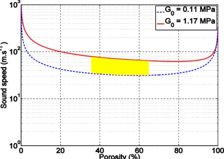
We performed calculations of the expected profiles of the velocity versus porosity using the Kuster and Toksöz54 model to gain further insight into the experimental observations. It has been
23
previously shown this model describes well samples with very low G0 values.14 In the Kuster and
Toksöz model, the acoustic longitudinal velocity is a function of only three parameters; the porosity Φ, the elastic bulk (K0) and shear storage moduli (G0) of the non-porous matrix. Therefore,
we measured the shear storage moduli of non-porous materials prepared using the same PDMS formulations as the polyMIPEs. The storage moduli of the non-porous materials were found to range from 110 and 1170 kPa. The value of K0 is typically of 1 GPa for this type of matrix. In
Figure 6 we plot the expected evolution of the velocity versus porosity profile for different values of the shear storage modulus of the non-porous polymer matrix that are comprised between110 and 1170 kPa.
Figure 6. Evolution of the acoustic longitudinal velocity as a function of porosity for different
values of the shear storage modulus G0 of the non-porous matrix. Calculations are obtained from
the Kuster-Toksöz model. The yellow domain represents the expected acoustic velocity values for the different samples, which are comprised between 30 and 70 m/s.
24
The curves obtained from the calculations for these values of the shear moduli and porosity values between 0.36 and 0.66 are in good agreement with the measured value of the acoustic velocity (~ 40 m/s) and does not significantly depend on the porosity and on the shear modulus in these ranges of shear moduli and porosity values (from 40 to 60%). This is shown in the yellow shaded area in Figure 6, which is the expected domain of sound velocity for the different materials presented in this study. From this graph, we expect the acoustic velocity of these samples to be between 30 and 70 m/s. Therefore, the results are in reasonable agreement with the predictions of the Kuster-Toksöz model. Additional work is under progress in our laboratory to more precisely determine the velocity and the acoustic attenuation of these materials.
Conclusions
This work has demonstrated the synthesis of soft polyMIPEs using a macromolecular thiol-ene reaction to prepare porous networks. The ratio of the thiolated-PDMS to the vinyl-terminated PDMS does not affect the properties of the initial emulsion, or porosity of the resulting polyMIPE, but the stoichiometric ratio of the PDMS reagents does control the storage moduli of the materials. The materials properties of the polyMIPEs could also be directly controlled by the amount of surfactant used to stabilize the emulsion and the volume of dispersed phase. Acoustic measurements show that the materials exhibit very low values of the sound velocity (~40 m/s), a value rarely attained in any solid materials.
Acknowledgements
TJM, PSH, and NA thank the National Science Foundation (DMR-1940518) for the resources to conduct this work, and thank Dr. Robert Lazenby, Hope Kumakli, and Prof. Ryan White for help with optical microscopy images.
25
KR and GB acknowledge use of the resources of the Advanced Photon Source, a U.S. Department of Energy Office of Science User Facility operated for the DOE Office of Science by Argonne National Laboratory under Contract No. DE-AC02-06CH11357. The USAXS data was collected at the APS on the beamline 9-ID-C. KR and GB also acknowledge Anh Tang from the Department of Chemical Engineering at the University of Cincinnati for help in conducting the X-ray scattering studies.
T.B., R.K. and O.M.M thank the Labex AMADEUS ANR- 10-LABEX-0042-AMADEUS with the help of the French state Initiative d’Excellence IdEx ANR-10-IDEX-003-02 the project BRENNUS ANR-15-CE08-0024 (ANR and FRAE funds) for the resources to conduct this work
26
References
1. Eissa, A. M.; Barros, F. S. V.; Vrljicak, P.; Brosens, J. J.; Cameron, N. R. Enhanced Differentiation Potential of Primary Human Endometrial Cells Cultured on 3D Scaffolds.
Biomacromolecules 2018, 19 (8), 3343–3350.
2. Zhang, T.; Silverstein, M. S. Robust, Highly Porous Hydrogels Templated within
Emulsions Stabilized Using a Reactive, Crosslinking Triblock Copolymer. Polymer 2019,
168, 146–154.
3. Whitely, M.; Cereceres, S.; Dhavalikar, P.; Salhadar, K.; Wilems, T.; Smith, B.; Mikos, A.; Cosgriff-Hernandez, E. Improved in Situ Seeding of 3D Printed Scaffolds Using Cell-Releasing Hydrogels. Biomaterials 2018, 185, 194–204.
4. Akay, G.; Birch, M.; Bokhari, M. Microcellular PolyHIPE Polymer Supports Osteoblast Growth and Bone Formation in Vitro. Biomaterials 2004, 25 (18), 3991–4000.
5. Streifel, B. C.; Lundin, J. G.; Sanders, A. M.; Gold, K. A.; Wilems, T. S.; Williams, S. J.; Cosgriff-Hernandez, E.; Wynne, J. H. Hemostatic and Absorbent PolyHIPE-Kaolin Composites for 3D Printable Wound Dressing Materials. Macromolecular Bioscience
2018, 18 (5), 1700414–1700424.
6. Yuan, W.; Chen, X.; Xu, Y.; Yan, C.; Liu, Y.; Lian, W.; Zhou, Y.; Li, Z. Preparation and Recyclable Catalysis Performance of Functional Macroporous PolyHIPE Immobilized with Gold Nanoparticles on Its Surface. RSC Advances 2018, 8 (11), 5912–5919.
7. Yavuz, E.; Cherkasov, N.; Degirmenci, V. Acid and Base Catalysed Reactions in One Pot with Site-Isolated PolyHIPE Catalysts. RSC Advances 2019, 9 (15), 8175–8183.
27
8. Noll, W. The Polymeric Organosiloxanes. Chemistry and Technology of Silicones, 1st ed.;
Academic Press Inc.: New York, 1968; p 246–331.
9. Tonhi, E.; Collins, K. E.; Collins, C. H. High-Performance Liquid Chromatographic Stationary Phases Based on Poly(Dimethylsiloxane) Immobilized on Silica. Journal of
Chromatography A 2005, 1075 (1-2), 87–94.
10. Jin, Y.; Kumar, R.; Poncelet, O.; Mondain-Monval, O.; Brunet, T. Flat Acoustics with Soft Gradient-Index Metasurfaces. Nature Communications 2019, 10 (1), 1–6.
11. Brunet, T.; Merlin, A.; Mascaro, B.; Zimny, K.; Leng, J.; Poncelet, O.; Aristégui, C.; Mondain-Monval, O. Soft 3D Acoustic Metamaterial with Negative Index. Nature
Materials 2014, 14 (4), 384–388.
12. Ba, A.; Kovalenko, A.; Aristégui, C.; Mondain-Monval, O.; Brunet, T. Soft Porous Silicone Rubbers with Ultra-Low Sound Speeds in Acoustic Metamaterials. Scientific
Reports 2017, 7 (1), 1–6.
13. Kovalenko, A.; Zimny, K.; Mascaro, B.; Brunet, T.; Mondain-Monval, O. Tailoring of the Porous Structure of Soft Emulsion-Templated Polymer Materials. Soft Matter 2016,
12 (23), 5154–5163.
14. Kovalenko, A.; Fauquignon, M.; Brunet, T.; Mondain-Monval, O. Tuning the Sound Speed in Macroporous Polymers with a Hard or Soft Matrix. Soft Matter 2017, 13 (25), 4526–4532.
15. Brun, N.; Ungureanu, S.; Deleuze, H.; Backov, R. Hybrid Foams, Colloids and beyond: From Design to Applications. Chem. Soc. Rev. 2011, 40 (2), 771–788.
16. Kimmins, S. D.; Cameron, N. R. Functional Porous Polymers by Emulsion Templating: Recent Advances. Advanced Functional Materials 2010, 21 (2), 211–225.
28
17. Pulko, I.; Krajnc, P. High Internal Phase Emulsion Templating - A Path To
Hierarchically Porous Functional Polymers. Macromolecular Rapid Communications
2012, 33 (20), 1731–1746.
18. Silverstein, M. S. PolyHIPEs: Recent Advances in Emulsion-Templated Porous Polymers. Progress in Polymer Science 2014, 39 (1), 199–234.
19. Kobayashi, T.; Saitoh, H.; Fujii, N.; Hoshino, Y.; Takanashi, M. Porous Membrane of Polydimethylsiloxane by Hydrosilylation Cure: Characteristics of Membranes Having Pores Formed by Hydrogen Foams. Journal of Applied Polymer Science 1993, 50 (6), 971–979.
20. Grosse, M.-T.; Lamotte, M.; Birot, M.; Deleuze, H. Preparation of Microcellular Polysiloxane Monoliths. Journal of Polymer Science Part A: Polymer Chemistry 2007,
46 (1), 21–32.
21. Martina, A. D.; Hilborn, J. G.; Kiefer, J.; Hedrick, J. L.; Srinivasan, S.; Miller, R. D. Siloxane Elastomer Foams. ACS Symposium Series Polymeric Foams 1997, 8–25. 22. Hilborn, J. G.; Della Martina, A.; Plummer, C. J.G.; Hedrick, J. L.; Miller, R. D.
Emulsion-derived microporous siloxane foams Polymer Preprints 1996, 37, 773-774. 23. Tebboth, M.; Jiang, Q.; Kogelbauer, A.; Bismarck, A. Inflatable Elastomeric
Macroporous Polymers Synthesized from Medium Internal Phase Emulsion Templates.
ACS Applied Materials & Interfaces 2015, 7 (34), 19243–19250.
24. Kataruka, A.; Hutchens, S. B. PDMS Polymerized High Internal Phase Emulsions (PolyHIPEs) with Closed-Cell, Aqueous-Filled Microcavities. Soft Matter 2019, 15 (47), 9665–9675.
29
25. Wu, R.; Menner, A.; Bismarck, A. Macroporous Polymers Made from Medium Internal Phase Emulsion Templates: Effect of Emulsion Formulation on the Pore Structure of PolyMIPEs. Polymer 2013, 54 (21), 5511–5517.
26. Zhang, H.; Zhao, R.; Pan, M.; Deng, J.; Wu, Y. Biobased, Porous Poly(High Internal Phase Emulsions): Prepared from Biomass-Derived Vanillin and Laurinol and Applied as an Oil Adsorbent. Industrial & Engineering Chemistry Research 2019, 58 (14), 5533– 5542.
27. Woodward, R. T.; Jobbe-Duval, A.; Marchesini, S.; Anthony, D. B.; Petit, C.; Bismarck, A. Hypercrosslinked PolyHIPEs as Precursors to Designable, Hierarchically Porous Carbon Foams. Polymer 2017, 115, 146–153.
28. Xie, S.; Svec, F.; FreChet, J. M. J. Preparation of Porous Hydrophilic Monoliths: Effect of the Polymerization Conditions on the Porous Properties of Poly (Acrylamide-Co-N,N?-Methylenebisacrylamide) Monolithic Rods. Journal of Polymer Science Part A:
Polymer Chemistry 1997, 35 (6), 1013–1021.
29. Zhang, T.; Sanguramath, R. A.; Israel, S.; Silverstein, M. S. Emulsion Templating: Porous Polymers and Beyond. Macromolecules 2019, 52 (15), 5445–5479.
30. Gibson, L. J.; Ashby, M. F. Cellular Solids Structure and Properties, 2nd ed.; Cambridge University Press: Cambridge, 1999.
31. Iha, R. K.; Wooley, K. L.; Nyström Andreas M.; Burke, D. J.; Kade, M. J.; Hawker, C. J. Applications of orthogonal "click" chemistries in the synthesis of functional soft
30
32. Kolb, H. C.; Finn, M. G.; Sharpless, K. B. Click Chemistry: Diverse Chemical Function from a Few Good Reactions. Angewandte Chemie International Edition 2001, 40 (11), 2004–2021.
33. Kade, M. J.; Burke, D. J.; Hawker, C. J. The power of thiol‐ene chemistry. Journal of
Polymer Science Part A: Polymer Chemistry 2010, 48 (4), 743–750.
34. Bowman, C. N.; Hoyle, C. E. Thiol-ene click chemistry. Angewandte Chemie
International Edition 2010, 49, 1540–1573.
35. Nguyen, K. D. Q.; Megone, W. V.; Kong, D.; Gautrot, J. E. Ultrafast Diffusion-Controlled Thiol–Ene Based Crosslinking of Silicone Elastomers with Tailored Mechanical Properties for Biomedical Applications. Polymer Chemistry 2016, 7 (33), 5281–5293.
36. Sergent, B.; Birot, M.; Deleuze, H. Preparation of Thiol–Ene Porous Polymers by Emulsion Templating. Reactive and Functional Polymers 2012, 72 (12), 962–966. 37. Lovelady, E.; Kimmins, S. D.; Wu, J.; Cameron, N. R. Preparation of
Emulsion-Templated Porous Polymers Using Thiol–Ene and Thiol–Yne Chemistry. Polym. Chem.
2011, 2 (3), 559–562.
38. Langford, C. R.; Johnson, D. W.; Cameron, N. R. Chemical Functionalization of
Emulsion-Templated Porous Polymers by Thiol–Ene “Click” Chemistry. Polym. Chem.
2014, 5 (21), 6200–6206.
39. Ratcliffe, J. L.; Walker, M.; Eissa, A. M.; Du, S.; Przyborski, S. A.; Laslett, A. L.; Cameron, N. R. Optimized Peptide Functionalization of Thiol‐Acrylate Emulsion‐ Templated Porous Polymers Leads to Expansion of Human Pluripotent Stem Cells in 3D
31
Culture. Journal of Polymer Science Part A: Polymer Chemistry 2019, 57 (18), 1974– 1981.
40. Mezhoud, S.; Paljevac, M.; Koler, A.; Droumaguet, B. L.; Grande, D.; Krajnc, P. Novel Hypercrosslinking Approach toward High Surface Area Functional 2-Hydroxyethyl Methacrylate-Based PolyHIPEs. Reactive and Functional Polymers 2018, 132, 51–59. 41. Ilavsky, J.; Zhang, F.; Andrews, R. N.; Kuzmenko, I.; Jemian, P. R.; Levine, L. E.; Allen,
A. J. Development of Combined Microstructure and Structure Characterization Facility for in situ and operando Studies at the Advanced Photon Source. Journal of Applied
Crystallography 2018, 51 (3), 867–882.
42. Ilavsky, J.; Zhang, F.; Allen, A. J.; Levine, L. E.; Jemian, P. R.; Long, G. G. Ultra-small-angle X-ray scattering instrument and the advanced photon source: History, recent development, and current status. Metallurgical and Materials Transactions A 2012, 44 (1), 68–76.
43. Ilavsky, J.; Jemian, P. R. Tool Suite for Modeling and Analysis of Small-Angle Scattering Journal of Applied Crystallography 2009, 42 (2), 347–353.
44. Hu, N., Borkar, N., Kohls, D. and Schaefer, D.W. Characterization of porous materials using combined small-angle X-ray and neutron scattering techniques. Journal of
membrane science 2011, 379(1-2), pp.138-145.
45. Porod, G. Die Röntgenkleinwinkelstreuung Von Dichtgepackten Kolloiden Systemen.
Kolloid-Zeitschrift 1951, 124 (2), 83–114.
46. Debye, P.; Anderson, H. R.; Brumberger, H. Scattering by an Inhomogeneous Solid. II. The Correlation Function and Its Application. Journal of Applied Physics 1957, 28 (6), 679–683.
32
47. Ilavsky, J. Software for two- dimensional data reduction. Journal of Applied
Crystallography 2012, 45 (2), 324–328.
48. Beaucage, G.; Kammler, H. K.; Pratsinis, S. E. Particle Size Distributions from Small-Angle Scattering Using Global Scattering Functions. Journal of Applied Crystallography
2004, 37 (4), 523–535.
49. Cameron, N. R.; Sherrington, D. C. High Internal Phase Emulsions (HIPEs) — Structure, Properties and Use in Polymer Preparation. Biopolymers Liquid Crystalline Polymers
Phase Emulsion Advances in Polymer Science 1996, 163–214.
50. Wong, L. L. C.; Villafranca, P. M. B.; Menner, A.; Bismarck, A. Hierarchical Polymerized High Internal Phase Emulsions Synthesized from Surfactant-Stabilized Emulsion Templates. Langmuir 2013, 29 (20), 5952–5961.
51. Cameron, N. R.; Barbetta, A. The Influence of Porogen Type on the Porosity, Surface Area and Morphology of Poly(Divinylbenzene) PolyHIPE Foams. Journal of Materials
Chemistry 2000, 10 (11), 2466–2471.
52. Cameron, N. R.; Sherrington, D. C.; Albiston, L.; Gregory, D. P. Study of the Formation of the Open-Cellular Morphology of Poly(Styrene/Divinylbenzene) PolyHIPE Materials by Cryo-SEM. Colloid & Polymer Science 1996, 274 (6), 592–595.
53. Peng, S.; Hartley, P. G.; Hughes, T. C.; Guo, Q. Controlling Morphology and Porosity of Porous Siloxane Membranes through Water Content of Precursor Microemulsion. Soft
Matter 2012, 8 (40), 10493–10501.
54. Kuster, G. T.; Toksöz, M. N. Velocity and Attenuation Of Seismic Waves In Two‐Phase Media: Part I. Theoretical Formulations. Geophysics 1974, 39 (5), 587–606.