HAL Id: hal-02280742
https://hal.archives-ouvertes.fr/hal-02280742
Submitted on 10 Sep 2019
HAL is a multi-disciplinary open access
archive for the deposit and dissemination of
sci-entific research documents, whether they are
pub-lished or not. The documents may come from
teaching and research institutions in France or
abroad, or from public or private research centers.
L’archive ouverte pluridisciplinaire HAL, est
destinée au dépôt et à la diffusion de documents
scientifiques de niveau recherche, publiés ou non,
émanant des établissements d’enseignement et de
recherche français ou étrangers, des laboratoires
publics ou privés.
A Hybrid Bioimpedance Spectroscopy Architecture for a
Wide Frequency Exploration of Tissue Electrical
Properties
Achraf Lamlih, Philippe Freitas, Mohamed Moez Belhaj, Jérémie Salles,
Vincent Kerzérho, Fabien Soulier, Serge Bernard, Rouyer Tristan, Sylvain
Bonhommeau
To cite this version:
Achraf Lamlih, Philippe Freitas, Mohamed Moez Belhaj, Jérémie Salles, Vincent Kerzérho, et al.. A
Hybrid Bioimpedance Spectroscopy Architecture for a Wide Frequency Exploration of Tissue Electrical
Properties. IFIP/IEEE International Conference on Very Large Scale Integration (VLSI-SoC), Oct
2018, Verona, Italy. pp.168-171, �10.1109/VLSI-SoC.2018.8644829�. �hal-02280742�
A Hybrid Bioimpedance Spectroscopy Architecture
for a Wide Frequency Exploration of Tissue
Electrical Properties
Achraf Lamlih
1 2, Philippe Freitas
1, Mohamed-Moez Belhaj
1, Jérémie Salles
1,
Vincent Kerzérho
1, Fabien Soulier
1, Serge Bernard
1, Tristan Rouyer
2and Sylvain Bonhommeau
31University of Montpellier, LIRMM, CNRS, 161 rue Ada 34095 Montpellier Cedex 5, FRANCE 2Ifremer/MARBEC, Av. J. Monnet, 34203 Sète, France
3Ifremer/DOI, rue J. Bertho, 97822 Le Port, France
contact: [email protected] / [email protected]
Abstract—Bioimpedance spectroscopy (BIS) is a technique increasingly used for measuring the electrical properties of biological tissues. Choosing an integrated system architecture for bioimpedance spectroscopy is very dependent on the application and ruled by several constraints such as precision, bandwidth and measurement time. This paper presents a hybrid architecture providing fast measurement time while maximizing precision. This new architecture has been defined for a wide exploration of electrical properties of biological tissues. It combines the frequency sweep and multitone measurement techniques. Using the multitone measurement over the α dispersion and a frequency sweep over the β dispersion, enable the system architect to overcome the design challenges faced when using each technique separately. Its critical blocks are optimized for a bandwidth up to 10 MHz, thus covering the α and β frequency ranges, an example of the design optimization is detailed for the current driver.
I. INTRODUCTION
Bioimpedance spectroscopy (BIS) is a technique increas-ingly used for measuring the electrical properties of biological tissues [1]. Since bioimpedance is a function of the physio-logical processes, variations of the composition of biophysio-logical tissues can be seen as variations of the electrical impedance of the tissue.
In order to measure bioimpedance, current stimulation is generally used. Thus, a current containing a single or multiple frequencies is injected in the tissue under test via electrodes, the bio-modulated response voltage is then measured to deter-mine the impedance transfer function.
Due to its non-invasive nature, its low cost and its ability to achieve low-power consumption, BIS is a suitable technique for long periods of monitoring. In fact, its use can improve the quality of healthcare delivered through earlier diagnosis and less invasive procedures.
Choosing an integrated system architecture for BIS is a dif-ficult task as it is ruled by several constraints such as precision, bandwidth and measurement time. In the literature, two types of architectures could be found, frequency sweep based archi-tectures and multitone-based archiarchi-tectures. These archiarchi-tectures provide different trade-offs between measurement time and precision. This paper presents a hybrid architecture providing
fast measurements while maximizing precision. It has been defined for biological tissue electrical properties exploration over a wide frequency range. Its critical blocks are optimized for a bandwidth up to 10 MHz, an example of the design optimization is detailed for the current driver.
II. BIS ARCHITECTURES
A. Constraints
Building an integrated system for BIS is very dependent on the application and ruled by several constraints. The main constraints facing a BIS integrated system designer are bandwidth, precision and measurement time.
In the literature, many applications using single frequency bioimpedance measurements can be found. However, for a rigorous characterization of the biological tissue composition, the complex impedance needs to be analyzed over a large range of frequencies. In fact, each tissue molecule has a different response to a given frequency. Indeed the electrical permittivity of biological tissues decreases in three main steps corresponding to three dispersions [2] : the α dispersion (10 Hz to 10 KHz), the β dispersion (10 KHz to 10 MHz) and the γ dispersion (≥ 10 MHz ). Since α and β dispersions are associated with the most relevant biological aspects [3], BIS integrated systems should be able to cover at least over these frequency ranges (10 Hz to 10 MHz). The Signal to Noise Ratio (SNR) is used as a precision metric. SNR cannot be improved by increasing the amplitude of the excitation signal, since it is limited by the safety requirements. Thus, care must be taken in order to maximize SNR over the frequency range of interest. Finally, in order to respect the system invariance criterion, measurement time should be as short as possible.
In general, two types of architectures could be found in the literature. Frequency sweep based architectures provide maximum precision while having long measurement times. On the other hand, multitone-based architectures provide short measurement times but their precision decreases with the number of frequency components in the excitation signal.
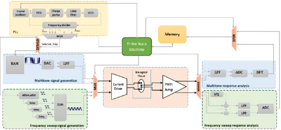
Fig. 1. Hybrid bioimpedance spectroscopy architecture
B. Multitone architectures
In BIS applications where the properties of the tissue under test are rapidly changing over time, fast BIS should be performed in order to respect the system invariance criterion. A solution is to use multitone signals in order to cover the chosen frequency range in a short time frame. However the energy of the signal is spread among its frequency points. Thus, multitone-based architectures provide short measure-ment times but their precision decreases with the number of frequency components contained in the excitation signal.
In the signal generation side, memory registers containing the binary multitone signal are sampled by a clock. The result is fed to a Digital-to-Analog Converter (DAC) that transforms the binary signal to pre-defined voltage levels. A Low Pass Filter (LPF) is used in order to get rid of the high frequency quantization noise. A current driver is then used to convert the multitone voltage to an excitation current.
In the response analysis side, an Instrumentation Amplifier (IA) is used to amplify the bio-modulated signal, an Analog-to-Digital Converter (ADC) is used to convert the amplified signal to the digital domain, then a Discrete Fourier Transform is computed in order to determine the phase and amplitude of the frequency components of interest.
C. Frequency sweep architectures
The signal to noise ratio (SNR) is a critical criterion in order to assess the quality of the excitation signal, and thus the measurement precision. The SNR cannot be improved by increasing the amplitude of the excitation signal, since it is limited by the safety requirements. In BIS applications where high precision is needed, frequency sweep architectures are used in order to have a maximal SNR, since the energy of the signal is concentrated over a single frequency point each time. In the signal generation side, a Phase locked Loop (PLL) is generally used as a frequency multiplier to get the higher frequency. On the negative feedback path, successive divisions are then performed to get the frequency components of in-terest. The digital signal is then scaled and delayed multiple
times and the sum of the results is used to construct a sine wave of the targeted frequency. The scale coefficients and the phase shifts are computed so that the constructed signal has the lowest total harmonic distorsion possible [4]. A current driver is then used to convert the constructed sine wave voltage to an excitation current.
In the response analysis side, an IA is used to amplify the bio-modulated signal, then a lock-in amplifier followed by a low rate ADC feed the memory with bit words representing the real and the imaginary parts of the impedance.
D. Proposed hybrid architecture
When analyzing the two architectures previously detailed, an integrated circuit designer could notice that the constraints vary all over the α and β frequency ranges. In fact, at the α dispersion, the frequency sweep architecture has longer measurement times since we process the measurement chain entirely for each frequency. Moreover, for response analysis, the LPF establishment time is significant since it operates at low frequencies. At the β dispersion, the multitone architecture needs high sampling frequencies for the generation side in order to push further quantization noise. On the other hand, for the response analysis side, a high frequency ADC is needed which brings design complexity. Moreover, at the β frequency range, the bioimpedance magnitudes are low (tens of Ohms to several Ohms). Thus, the energy of each of the frequency components contained in the multitone excitation signal is low, making the specifications of the IA difficult to reach.
Fig. 1 shows the proposed architecture, it is a combina-tion of the frequency sweep and the multitone architectures described in subsections II-B and II-C. It uses a finite state machine in order to choose the multitone generation and anal-ysis for the frequencies of the α frequency region (10 Hz to 10 KHz), then it switches to the frequency sweep architecture for the β frequency region (10 kHz to 10 MHz) using the dif-ferent multiplexers and demultiplexers. The current driver and the instrumentation amplifier are common blocks to the two architectures. Thus, their design process is critical since they
Io- Io+ V1 V2 V1 V2 Vin- Vin+ V3 V3 V4 Vdd V4 M1B M1A M2B M3B M2A M3A M4B M4A M5A M5B M6B M6A M7A M7B M11A M11B M12B M10A M12A M10B M11C M11D M8A M8B R M9A M9B Vref M13A M13B Ibias Idpb Idpa
Vref Vref Vref
Ibias
Ibias
Ibias
Fig. 2. Current driver architecture
should be able to cover both the α and β frequency ranges. As an example, the current driver design and optimization is detailed in the next section.
III. CURRENT DRIVER DESIGN AND OPTIMIZATION
The current driver is a critical block of the presented architecture. Since α and β dispersions are associated with the most relevant biological aspects [3], the current should have a constant amplitude over these frequency ranges. This is achieved by having a large output impedance compared to the load. In fact, at lower frequencies, the sum of the electrodes-interface and tissue impedances have the highest magnitudes. Whereas at higher frequencies, stray capacitance represents the biggest challenge since it shunts the output resistance of the current driver which reduces its value.
A. Topology
Fig.2 shows the architecture of the current driver [5]. It is a symmetrical fully-differential Operational Transconductance Amplifier (OTA). The first stage of the OTA consists of a degenerated differential pair. A degeneration resistance was added to the M1 transistors in order to enhance the linearity of the transfer function and to maximize the range of input voltage. The current across the differential pair branches has been set in order to have a bandwidth of operation covering the α and β frequency dispersions.
The output stage is a critical part of the current driver structure. It needs to provide a high output impedance while enabling a maximum output swing. Using regulated cascode current mirrors as the output stage architecture provides the best compromise between a high output resistance and the lowest output voltage. Since the OTA is fully-differential, a common-mode feedback (CMFB) loop is implemented to stabilize the common-mode output voltage at half supply [6]. Due to low supply voltage specifications and in order to compensate for process variations, the output DC level is tunable using an independent reference voltage (Vref).
Vin+ V3 M3B M6B M5B M6BB M2BB M4B M1B M2B Vdd Ibias Idpb Ibias
Fig. 3. Improved regulated cascode architecture
B. Output impedance increasing
The output stage of the current driver is critical. It has to provide an output current proportional to the input current at the high impedance output node. The output current amplitude needs to be constant regardless of loading. The important factors defining the performance of the output stage are thus output impedance, minimum output voltage and accuracy.
Bandwidth specifications imposed by the application require the use of short channel MOSFETs. A size reduction of the transistors leads to a decrease in the output resistance. Simple current mirror blocks or basic cascode structures are unable to provide an acceptable output resistance, especially at low frequencies where the load (electrode-tissue interface impedance) displays the highest impedance magnitudes, gener-ating measurements errors in that frequency range. Therefore, improved output stage architectures for higher performances should be used.
Regulated cascode current mirror have the highest output impedance compared to simple or Wilson cascodes. It uses negative feedback in order to enhance the output impedance.
The improved regulated cascode shown in Fig.3 is the basic block of the output stage. In order to minimize loading effects, the transistor M6B is used to enhance the output impedance
by a gm ∗ ro factor compared to basic cascode structures. The output impedance of the improved regulated cascode can be written as :
Rout = roM4∗ roM6∗ gmM6∗ roM5∗ gmM5 (1)
The main drawback of the regulated cascode is the output minimum voltage, which is equal to Vth+ 2Vef f. This could
be improved to around 2Vef f by using the M6 transistors in
weak inversion. Although the matching of the M6 transistors
will be affected when operating in weak inversion, the loop gain of the structure is so important that the matching errors are negligible.
In order to enhance the accuracy of the current mirror, the drain to source voltages of M3Band M4Bshould be equalized.
Since the Vdsof M4Bis imposed by the gate voltage of M6B,
the proposed solution consists in using in a mesh an M6BB
transistor of similar size as M6Bbiased with the same current,
VdsM4B = VgsM6B (2)
VgsM6B = VgsM 6BB (3)
VdsM3B = VgsM2BB − VgsM2B + VgsM6BB (4)
VdsM3B = VgsM6BB = VdsM4B (5)
C. Results
The current driver was designed in a 0.18 µm AMS CMOS process operating at 1.8 V power supply. The current driver is capable of providing currents up to 600 µA peak to peak. The circuit design, simulations and layout were developed with Cadence suite using the toolkit provided by the foundry.
The Frequency response of the current driver transconduc-tance is presented in Fig.4. It has a transconductransconduc-tance of 860 µS up to 4 MHz decreasing to 854 µS at 8 MHz. The cutting frequency is located at 67 MHz. The current driver was loaded with a 1 kΩ resistor with only its intrinsic stray capacitance.
100 101 102 103 104 105 106 107 108 109 Frequency (Hz) 300.0 350.0 400.0 450.0 500.0 550.0 600.0 650.0 700.0 750.0 800.0 850.0 900.0 Tr ansc onduc tanc e (uS)
Fig. 4. Current driver bandwidth
Total Harmonic Distortion (THD) was simulated for a 400 µA peak to peak output current. The simulation results have showed a THD below 0.3% at low frequencies increasing to 0.6% at 8 MHz. 103 100 10 101 102 103 104 105 106 107 108 109 104 105 107 106 108 Frequency (Hz) O utput I mpedanc e M ag nitude (Ω)
Fig. 5. Output impedance of the current driver
The frequency response of the output impedance of the current driver is presented in Fig.5. The output impedance is equal to 79 MΩ at DC up to 1 KHz. It decreases to 3.6 MΩ at 100 KHz, and to 324 kΩ at 1 MHz. The low frequency output impedance magnitudes are suitable for exploring the
physiological processes occurring in the α region. At higher frequencies, the output impedance values are several orders of magnitude higher than the electrode-tissue impedance, since it is expected to decrease in the β region. A research presented in [7] shows a comparison of the impedance magnitudes of several Ag/AgCl commercial electrodes in the frequency range (10 Hz-1 MHz), The average electrode-tissue impedance magnitudes were higher than 10 KΩ for frequencies below 10 KHz, equal to 5 KΩ at 10 KHz and 337 Ω at 1 MHz. The current driver output impedance results compared to the electrode-tissue magnitudes presented in [7] show that it is capable of providing measurements with an error of 0.02% at 10 KHz and 0.1% at 1 MHz.
IV. CONCLUSION
A hybrid architecture for bioimpedance spectroscopy has been presented. This new architecture has been defined for a wide exploration of the electrical properties of the biological tissue. It combines the frequency sweep and multitone mea-surement techniques, thus providing fast meamea-surement time and maximal precision over the α and β dispersions. More-over, using the multitone measurement over the α dispersion and a frequency sweep over the β dispersion, enable the system architect to overcome the design challenges faced when using each technique separately. The current driver and the instrumentation amplifier are common blocks to the two measurement techniques, they have been designed in order to cover a frequency range of 10 Hz to 10 MHz. As an example, the current driver design and optimization using 0.18 µm CMOS AMS process has been presented.
ACKNOWLEDGMENT
This research was part of the MERLIN-POPSTAR project funded by Ifremer and a Phd funded by Ifremer and labex Numev. We thank our colleagues from Ifremer/REM/RDT and RBE, CNRS, UM and IRD who provided insight and expertise that greatly assisted the research.
REFERENCES
[1] S. Grimnes and O. G. Martinsen, Bioimpedance and Bioelectricity Basics. Academic Press, 2014.
[2] H. P. Schwan, “Electrical properties of tissue and cell suspensions,” Advances in Biological and Medical Physics, vol. 5, pp. 147–209, 1957. [3] H. Dastjerdi, R. Soltanzadeh, and H. Rabbani, “Designing and imple-menting bioimpedance spectroscopy device by measuring impedance in a mouse tissue.” Journal of Medical Signals and Sensors, pp. 187–194, 2013.
[4] S. David-Grignot, A. Lamlih, M. M. Belhaj, V. Kerzérho, F. Azaïs, F. Soulier, P. Freitas, T. Rouyer, S. Bonhommeau, and S. Bernard, “On-chip generation of sine-wave summing digital signals: an analytic study considering implementation constraints,” Journal of Electronic Testing, vol. 34, no. 3, pp. 281–290, Jun 2018. [Online]. Available: https://doi.org/10.1007/s10836-018-5710-4
[5] A. Lamlih, P. Freitas, S. David-Grignot, J. Salles, V. Kerzérho, F. Soulier, S. Bernard, T. Rouyer, and S. Bonhommeau, “Wideband fully differen-tial current driver with optimized output impedance for bioimpedance measurements,” in 2018 IEEE International Symposium on Circuits and Systems (ISCAS), May 2018, pp. 1–5.
[6] W. M. C. Sansen, Analog Design Essentials. Springer, 2006. [7] M. Rahal, J. M. Khor, A. Demosthenous, A. Tizzard, and R. Bayford,
“A comparison study of electrodes for neonate electrical impedance tomography,” Physiological Measurement, vol. 30, no. 6, p. S73, 2009.