SMITHSONIAN MISCELLANEOUS COLLECTIONS VOLUME 62, NUMBER 5
lbobohtns
Jfunb
SINST.rc26 JAN1918
4 /' R A P'DYNAMICAL STABILITY OF AEROPLANES
(WITH THREE PLATES)BY
JEROME C. HUNSAKER, ENG. D.
ASSISTANT NAVAL CONSTRUCTOR, U. S. NAVY
Instructor in Aeronautical Engineering, Massachusetts Institute of Technology
ASSISTED BY
T. H. HUFF, S. B., D. W. DOUGLAS, S. B., H. K. CHOW, S. M.,
AND V. E. CLARK, CAPTAIN, U. S. ARMY
~IN;W*%
PER OR
(PUBLICATION 2414)
CITY OF WASHINGTON
PUBLISHED BY THE SMITHSONIAN INSTITUTION
rBAe orb ,atioe (Pr BALTIMORE, MD., U. S. A.
CONTENTS
PART I. LONGITUDINAL MOTION PAGE
i. Introduction and Conclusions... 1
2. T ype D esign... 6 3. M odel ... 7 4. W ing Coefficients ... 7 5. Longitudinal Balance... 12 6. Vector Representation... 16 7. Performance Curves... 17
8. Axes and Notation... 18
9. Equilibrium Conditions and Dynamical Equations of Motion... 20
io. Conversion to Moving Axes, Longitudinal Data... 25
uI. Resistance Derivatives, Longitudinal... 30
12. Damping . ---... 31
13. Oscillations in Pitch ... 33
14. Longitudinal Stability, Dynamical... 35
15. Conclusions (Longitudinal Dynamical Stability)... 43
PART II. LATERAL MOTION i. Lateral or Asymmetrical Tests... 45
2. Lateral Resistance Derivatives... 52
3. Rolling Moment due to Yawing...--... 53
4. Yawing Moment due to Rolling... 55
5. Damping of Roll... 57
6. Damping of Yaw... ... 59
7. Neglected Coefficients ... 62
8. Independence of Longitudinal and Lateral Motion... 62
9. Lateral Stability, Dynamical... 64
io. Character of Lateral M otion... 66
11. The "Spiral Dive... ... 68
12. R olling ... 70
13. The "Dutch Roll "... ... . 71
14. Comparison with other Aeroplanes... 75
111
1bobghtno f unb
PART I. LONGITUDINAL MOTION
i. INTRODUCTION AND CONCLUSIONS
The present dynamical investigation of the stability of motion of aeroplanes is based upon the well-known theory of small oscillations of rigid dynamics as first applied by Bryan 1 to aeroplanes and ex-tended by Bairstow.2
The necessary coefficients for use in the equa-tions of motion were determined by model tests in the wind tunnel of the Massachusetts Institute of Technology.
The application of model experiments to predict the performance of full-size aeroplanes is now so well established that no general discussion of the theory of models is undertaken. A great part of the actual experimental work was performed by Messrs. Huff and Douglas. The oscillating apparatus was designed by Mr. Chow under the direction of Professor E. B. Wilson of the Department of Mathematics. Captain V. E. Clark, U. S. A., while a student in aeronautical engineering, designed an aeroplane which was selected as one type for investigation.
It is necessary to acknowledge the cordial interest taken in the work by Professor C. H. Peabody, head of the Department of Navat Architecture. From the beginning of aeronautical research in his department, Professor Peabody has offered the warmest encourage-ment by countless arrangeencourage-ments to facilitate progress and to pre-vent interruptions.
Following the analysis of Clark's aeroplane, the work was repeated for a model of a military aeroplane known as Curtiss JN2.' The
' G. H. Bryan, " Stability in Aviation."
' Technical Report of the Advisory Committee for Aeronautics, London, 1912-13.
' Plans and description given in "First Annual Report of the National Ad-visory Committee for Aeronautics" (Report No. i, "Report on Behavior of Aeroplanes in Gusts," by J. C. Hunsaker and E. B. Wilson, Washington, D. C.,
1916), Senate Document No. 268, 64th Cong., 1st Sess.
SMITHSONIAN MISCELLANEOUS COLLECTIONS, VOL. 62, No. 5
2 SMITHSONIAN MISCELLANEOUS COLLECTIONS VOL. 62
Curtiss Aeroplane Company gave their full cooperation with a desire to learn what improvements in the design might be suggested by our stability calculations. Dr. A. F. Zahm of the research department of that company made careful tests to locate the center of gravity and to determine the moments of inertia of the actual aeroplane.
The Curtiss machine is a practical aeroplane with powerful con-trols, which does not pretend to possess any particular degree of stability. The Clark aeroplane, on the other hand, was designed to be inherently stable while departing as little as possible from the lines of the ordinary military aeroplane as typified by the Curtiss JN2.
The comparison of these two aeroplanes is interesting and leads to the conclusion that inherent dynamical stability, both longitudinal and lateral, may be secured in an aeroplane of current type by careful adjustment of its surfaces and without material effect on controlla-bility or performance.
The discussion in detail is confined to the Clark model, for brevity of presentation, and the results only of the parallel calculations for the Curtiss model are introduced where a comparison is suggested. In Part I the general equations of motion are deduced in a simpli-fied form which applies to horizontal flight in still air. The longi-tudinal motion is then considered separately and the necessary aerodynamical constants determined from wind tunnel tests. It is
found that the longitudinal motion, if disturbed by any accidental cause, is a slow undulation involving a rising and sinking of the aeroplane as well as a pitching motion. This undulation is stable for high aeroplane speeds since it is rapidly damped out. At lower speeds, the undulation is less heavily damped until at a certain critical low speed the damping vanishes. For speeds below this critical speed, the undulations tend to increase in amplitude with each swing and the longitudinal motion is, therefore, unstable.
Similar calculations for the Curtiss aeroplane show a similar critical speed below which the longitudinal motion is unstable. It is believed that the existence of instability at low speeds has not been indicated before, and it is hoped that the recommendations made to reduce the critical speed may be of assistance to designers.
It appears a simple matter to secure any desired degree of longi-tudinal stability by the use of properly inclined tail surface, and by the use of light wing loading. It is pointed out that.excessive statical stability, as indicated by strong restoring moments, is undesirable and may cause the motion to become violent in gusty air. This
vio-NO. 5 STABILITY OF AEROPLANES-HUNSAKER AND OTHERS lence of motion may seriously impair the pilot's control and the aeroplane may " take charge " at a critical time.
However, the longitudinal motion for any particular speed of flight may be made dynamically stable, while at the same time only slightly stable in the static sense, by the use of a large tail surface which lies very nearly in the relative wind. If the minimum of statical stability be combined with the maximum of damping, the pitching will be very slow and heavily damped. The longitudinal motion can then be dynamically stable and yet be without violence of motion in gusty air. The general prejudice among pilots against " very stable " aero-planes is believed to be justified. It cannot be too strongly insisted upon that true dynamical stability is better given by damping than by stiffness.
Experience with rolling of vessels has led to the design of vessels of small metacentric height (a measure of statical stability) fitted with generous bilge-keels (damping surface) for passenger carrying. An effort is made to get away from the violence of motion associated with stiffness.
In Part II, the lateral or asymmetrical motion is investigated. The necessary aerodynamical constants are determined by wind tunnel tests wherever practicable and two coefficients which cannot readily be found experimentally are calculated by a simple approximate method. The character of the motion as indicated by the solution oTf the determinant formed from the equations is then discussed.
It is found that the lateral motion is a combination of a roll, yaw, and side slip or " skidding." Using approximate methods, the com-bined motion is resolved into three components, two of which are important.
One type of motion is a spiral subsidence if stable or divergence if unstable. The Clark aeroplane becomes spirally unstable at low speed. The motion is a " spiral dive " due to an overbank and a side slip inwards. The aeroplane makes a rapid turn with rapidly increas-ing bank accompanied by side slippincreas-ing inwards. The instability is such that an initial deviation from course will double itself in about
7 seconds.
It is shown that the spiral motion may be made stable by adequate fin surface above the center of gravity or upturned wings and by reduction in " weather helm " due to too much rudder or fin sur-face aft.
SMITHSONIAN MISCELLANEOUS COLLECTIONS
The Curtiss aeroplane shows the same sort of spiral instability at high speeds. This aeroplane had no dihedral angle of wings and had a large rudder and deep body.
The second type of motion has been called a "Dutch roll" -from analogy to a figure in ice skating. The aeroplane takes up an oscilla-tion in yaw and roll simultaneously. It swings to the right banking
for a right turn, then swings back to the left banking for a left turn.
The combined yaw and roll has a fairly rapid period. The Clark model at all speeds shows that this motion is heavily damped and hence stable. At high speed, the period is 6 seconds and an initial amplitude is damped to half value in less than 2 seconds. At low speed the period is 12 seconds, damped to half amplitude in 6 seconds. It appears from an approximate calculation that the " Dutch roll " may become unstable if an aeroplane has too much high fin surface and if there be not sufficient " weather helm " or rear fin surface. It is seen that these conditions are the reverse of those for spiral insta-bility. The conflicting nature of the requirements for stability in these two kinds of motion suggests that an aeroplane is unlikely ever to be unstable in each sense. It also indicates the difficulty of obtain-ing lateral stability by raised wobtain-ing tips.
In confirmation of theory, we found the Curtiss spirally unstable at high speed and stable in the " Dutch roll," while at low speed the spiral motion was stable and the " Dutch roll" unstable. The period was 6 seconds and an initial amplitude doubled itself in 8 seconds.
It is believed that the majority of modern aeroplanes of ordinary type are spirally unstable because of excess of fin surface aft. When attempts have been made to remedy this fault by use of a large dihedral angle upwards for the wings, matters have been made worse. It is only to be expected that in overcorrecting spiral in-stability a " Dutch roll " of more or less violence may be introduced. Especially in gusty air would one expect high fin surface to produce violent rolling.
The Clark aeroplane has very slight rise of wings, about 1*6, and a small rudder. It is shown that at ordinary speeds this aero-plane is stable in every sense, both longitudinally and laterally. Whether this stability is excessive can only be determined by actual flight experience in turbulent air. However, it has appeared possible to secure a degree of stability in every sense in an aeroplane of con-ventional type.
The object of the research has been to show how various features of design may affect the motion of the aeroplane and only incidentally
dim
VOL. 6:2 4
NO. 5 STABILITY OF AEROPLANES-HUNSAKER AND OTHERS 5 to produce a stable aeroplane. The discussion has been confined to motion in still air. If an aeroplane be unstable in still air it is obviously worse off in gusts. The converse is, unfortunately, not true, for an aeroplane which is very stable in still air may be so stiff that in turbulent air it will be violently tossed about.
It is conservative to conclude that aeroplanes should not be un-stable and that they need not be, since slight changes in the nature of adjustments suffice to correct such instability of motion.
In view of the military use of aeroplanes inside the zone of fire the probability of controls becoming inoperative is ever present. An inherently stable aeroplane, with controls abandoned or shot away, could still be operated by a skilful pilot by manipulation of the motor power alone.
Any sort of automatic (or gyroscopic) stabilizer which operates on the controls is of no use when those controls fail, and it should be judged as an accessory to assist a pilot rather than as a cure-all
for the inherent instability of an aeroplane's motion.
The ordinary type of aeroplane readily lends itself to adjustments which make for inherent stability of motion and there is no reason to seek radical changes of type to insure stability. Freak aeroplanes of great "stability" may be excessively stable in some ways and frankly unstable in others. It is likely that the most satisfactory aeroplane will be only slightly stable and that this aeroplane will in any possible attitude be easily controlled by the pilot.
Controllability and statical stability are to some extent incompatible. Dynamical stability requires some amount of statical stability and considerable damping. It appears to be of advantage to provide the minimum of statical stability and the maximum of damping. Then the aeroplane's motion will be of very long period but heavily damped. It is believed that the methods of investigation here described may be applied to any type of aeroplane, and, by the systematic variation of one feature of design at a time, a full understanding may be had of the effect on the motion of each change. The process is of necessity laborious, but compared with the difficulty of full-scale experiment in the open air, the model method is rapid and inex-pensive. It is rarely possible in actual flying to obtain any idea of the effect of slight changes in design. Weather conditions, motor troubles, personal peculiarities of pilots, etc., tend to add to the com-plexity of an otherwise very simple problem.
Furthermore, experimental flying is dangerous. For example, I knew a pilot who, to determine whether a new aeroplane was spirally
SMITHSONIAN MISCELLANEOUS COLLECTIONS
unstable, took his machine up to a good altitude and allowed it. to get into a spiral dive. The machine made five turns of a rapidly winding and. contracting helix before he could bring it out on a horizontal path. If the controls had been only a little less powerful the machine would surely have crashed to the ground. That the controls were adequate was purely a matter of good fortune. The experiment was a success in that spiral instability was demonstrated. Only a few minutes of time was required. However, no information was obtained as to. the degree of instability present nor as to what par-ticular changes would remedy matters. To complete the experiment, it would be necessary to repeat the dangerous feat fcr every change which suggested itself. Naturally, a designer will-be very economical in his suggestions under such conditions.
2. TYPE DESIGN
The type aeroplane selected for the first investigation is a two-place biplane tractor designed by Captain V. E. Clark, U. S. A., while a student in the graduate course in aeronautical engineering at the Massachusetts Institute of Technology. This aeroplane is considered to be representative of modern practice in aeroplane design. Its principal dimensions are as follows:
Wing area, including ailerons... 464 Span, feet ... 41 Aspect ratio ... 7
G ap ... 6.37 Dihedral of wings, degrees... 176-75 Area, stabilizer ... 16.1
Area, elevators ... 16.0
Area, rudder ... 9.35 Length, body ... 24.5 Depth, body, maximum ... 3.2
Width, body, maximum ... 3.3
W eight, bare ... 1,070
W eight, personnel ... 320
W eight, fuel and oil... 415 Weight, full load... 1,805
Radii of gyration ... Brake horse-power ...
Fuel and oil per B. H. P., hour ...
5.2 4.65 6.975 110 sq. ft. max., 40.2 mean. f f. sq. sq. sq. ft. ft. ft. lbs. lbs. lbs. lbs. ft., ft., ft., ft. ft. ft. in in in roll. pitch. yaw. 0.73 lb. 6 VOL. 62 . . . ..
II __-~
NO. 5 STABILITY OF AEROPLANES-HUNSAKER AND OTHERS 7
Maximum speed ... 87 miles per hour. Minimum speed ... 35 miles per hour. Initial rate of climb... 900 ft. per min. Best glide ... ' in 9
Endurance, full power ... 5.6 hours.
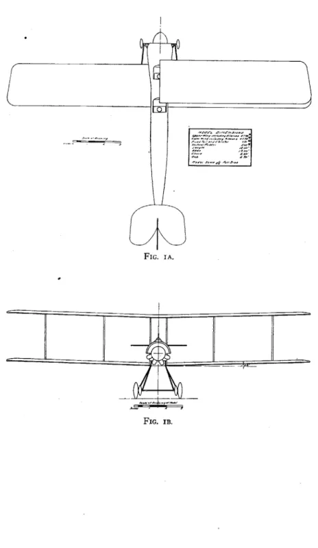
Endurance, reduced power, 14 hours at.. 47 miles per hour. 3. MODEL
A model, scale, was made by Edward Tighe, model maker, giving a span of 1.58 feet. The size of the model was limited by the size of the wind tunnel which is 16 square feet in section. The model is shown in figure I (see pp. 8 and 9). Note that wires are omitted and struts are made round instead of " stream line " in section. It is believed that the effects of these changes on total resistance largely counterbalance each other. This model was carefully shellacked and polished to minimize skin friction. The model is, of course, much more smooth than the full-size aeroplane, as it should be, in order that the surfaces may remain geometrically similar. Model work was to the nearest hundredth of an inch. No propeller was fitted, but in the design account was taken of the propeller race in augmenting
resistance.
For simplicity, the model was made with trailing ailerons or wing flaps integral with the wings. This somewhat increases the effective supporting area. The stabilizer and elevator were made in one, corresponding to the elevator flaps in neutral position. These points are made clear on figure I.
4. WING COEFFICIENTS
In the course of the design, a wing section was devised by Clark which showed a low resistance at high speed and small angle of attack and at the same time was thick enough to permit the use of robust wing spars. A model of this wing was made, of 18 inches span by 3 inches chord, and tested in the wind tunnel. For various angles of wing chord to wind, the lift L, drift D in pounds, and pitching moment M in pounds-inches were observed for a wind of
30 miles per hour; air of density .07608 pound per cubic foot.
The wind tunnel and balance are duplicates of the 4-foot installa-tion at the Nainstalla-tional Physical Laboratory, England, and reference may be made to the technical report of the Advisory Committee for Aeronautics, year 1912-13, for a description of the apparatus and method of operation.
SMITHSONIAN MISCELLANEOUS COLLECTIONS
FIG. IA.
FIG. IB.
NO. 5 STABILITY' OF AEROPLANES-HUNSAKER AND OTHERS 0 0 C9 -wl-mm -wg I
-~~1
10 SMITHSONIAN MISCELLANEOUS COLLECTIONS VOL. 62
The lift and drift coefficients Ky and Kx were computed from the observed L and D, using such units that the coefficient is pounds force per square foot area per mile hour velocity. Curves of coefficients are given on figure 2, which also shows the ratio L/D, a measure of
N 4: 'I' S%< 'J /--. 26:< ////3 / .002.
~~/
e -- _ -/s~~
__ .006 .00/16 _ Yod .00'4' ___/___ _/_ 01 - -le 0 .4 6 -C /0 /l /f /6 Ao/f C/0o0-d to AY/./d . Fic. 2.-Wing coefficients.
the effectiveness of the wing. A maximum L/D ratio of 18 was found for an angle of attack of 3'. For a 41-foot wing at 70 miles per hour, it is believed that the lift coefficient is not greatly different, but that the drift coefficient at small angles is materially reduced. The effect is to increase the ratio L/D. Results of tests at the National Physical Laboratory (Tech. Rept. Adv. Comm. Aero.,
1912-NO. 5 STABILITY OF AEROPLANES-HUNSAKER AND OTHERS
13, p. 81) were applied to the L/D curve for our model to obtain an
approximate curve of L/D to apply to the full-size wing. As a monoplane surface, we get a maximum value of L/D of about 20. The particular design is a biplane of aspect ratio 7. Well-known corrections for biplane interference loss and aspect ratio gain were applied to get a corrected curve for use in the design.
"4.
UP'. I Owen~
as1 th cntourt ofm th scio.Cete f rssrei dfned- h
vetr with-- th-pan-o- te hod tcs en tha, thei win setio
i sy s 3 if th.P e zwsng er a
.04S ols
00
Oo/
FIG. 3.-Wing section dimensions and resultant force vectors.
The center of pressure for this wing is shown b figure 3, as well as the contour of the section. Center of pressure is defined as the intersection of the resultant force on the wing (represented as a -vector) with the plane of the chord. It is seen that the wing section is unstable longitudinally at small angles. That is, if the wing heads down so that the angle of attack becomes -30, the moment of the resultant force tends to turn it down still farther.
Applied to the aeroplane, it is necessary to balance and correct this tendency to dive by horizontal tail surfaces of proper size and attitude.
14 SMITHSONIAN MISCELLANEOUS COLLECTIONS VOL. 62
respectively. The discrepancy is I per cent only and is about the precision of the measurements. The comparison is best brought out
by eliminating reference to angle of attack as the effect of the change
in tail angle appears to be mainly to move the curves of L and D, plotted on i, to the right or left.
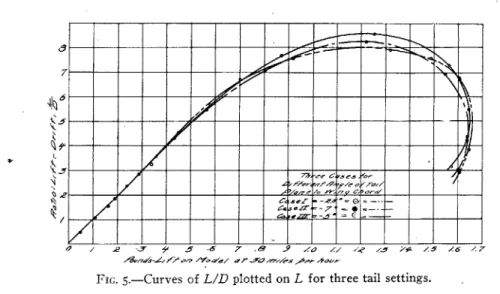
Figure 5 shows the ratio L/D for the model for cases I, II, and III, plotted on L in pounds as abscisso. For small values of L and angles of incidence between -2' and +20, corresponding in practice to high-flight velocity, the curves are practically identical. For angles
'9 /
2 ' f .6 7 19 x a Z/ ZO /~ Y 1 1/ /7
FIG. 5.-Curves of L/D plotted on L for three tail settings.
of incidence near 80, the L/D ratio for case III is 8.6, while it is 8.2 for case II, and 8.o for case I.
It appears, therefore, that changing the angle of tail surface has but slight effect on the lift and drift of the aeroplane. The actual aeroplane should have the same maximum and minimum speeds in any case since the maximum lift and minimum drift are about the same regardless of angle of tail surfaces.
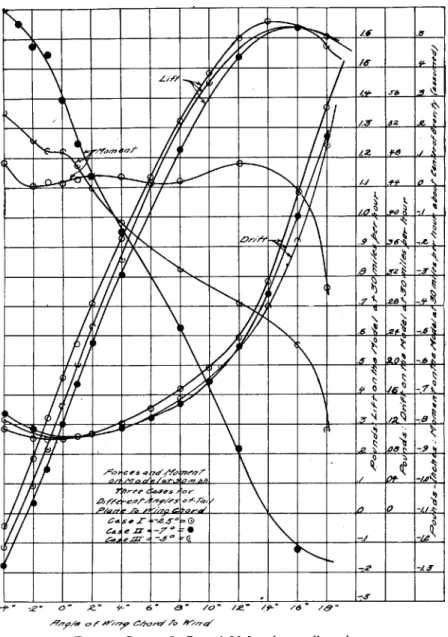
The statical stability against longitudinal pitching is, however, very different for the three cases. Thus the pitching moments (ob-served about the spindle and converted to pitching moments about the assumed center of gravity) are as follows, in pounds-inches on the model at 30 miles per hour. Positive angles and positive moments are stalling angles and stalling moments respectively.
7 - - __'__ __
- - - -
-7'
NO. 5 STABILITY OF AEROPLANES-HUNSAKER AND OTHERS ___ ___ ___ J _e _____
~
~
A ________* a&... 11- 10% - t 7-94'a 0 /VM -hh J 7M M *E-e e MZ9 e.Z27-_ _ _4
M-~-
__ __ __ __ __ _ M M M _ _ _ _ _ _ _ _ _ M . --~
FIG. 4.-Curves L, D, and M for three tail settings.
2
I3
14 SMITHSONIAN MISCELLANEOUS COLLECTIONS VOL. 62.
respectively. The discrepancy is I per cent only and is about the
precision of the measurements. The comparison is best brought out
by eliminating reference to angle of attack as the effect of the change
in tail angle appears to be mainly to move the curves of L and D, plotted on i, to the right or left.
Figure 5 shows the ratio L/D for the model for cases I, II, and III, plotted on L in pounds as abscissa. For small values of L and angles of incidence between -2' and +20, corresponding in practice to high-flight velocity, the curves are practically identical. For angles
V
4 / 2 5 5 6
~7
.49'9 oZ~
/~/
6FIG. 5.-Curves of L/D plotted on L for three tail settings.
of incidence near 8', the L/D ratio for case III is 8.6, while it is 8.2 for case II, and 8.o for case I.
It appears, therefore, that changing the angle of tail surface has but slight effect on the lift and drift of the aeroplane. The actual aeroplane should have the same maximum and minimum speeds in any case since the maximum lift and minimum drift are about the same regardless of angle of tail surfaces.
The statical stability against longitudinal pitching is, however, very different for the three cases. Thus the pitching moments (ob-served about the spindle and converted to pitching moments about the assumed center of gravity) are as follows, in pounds-inches on the model at 30 miles per hour. Positive angles and positive moments are stalling angles and stalling moments respectively.
6 _ _ _
NO. 5 STABILITY OF AEROPLANES-HUNSAKER AND OTHERS PITCHING MOMENTS, POUNDS-INCHES
Case I Case II Case III
-4 +.089 + -599 +.26 -2 +.008 + -473 +.16 -1 +.022 + .454 +.12 o
+.o16
+ .292 +.12 +1 +.030 + .143 +.07 +2 +.037 + .037 -. OI +4 +.039 - -159 -. 12 6 +.o16 8 +.023 - .476 -. 28 10 ... ... 12 +.o86 - .884 -- 39 14 16 -. 013 -1-328 -. 53 18 -. 336 -1.378 -. 82Case I, with tail at -2'75, shows very small pitching moments and may be said to be neutral for ordinary angles of' incidence. Thus if the aeroplane be flown at +20 incidence, in order to maintain
balance at this attitude the pilot must impress a diving moment of
-. 037 pound-inch (on the model) to overcome the stalling moment
+ .037 given above. Then if the aeroplane be accidentally tilted up to +12' by a wind gust or other cause, in the new attitude the net pitch-ing moment is still positive, and hence tends to tilt the machine still more. It is, therefore, unstable unless the pilot intervenes with the horizontal rudder.
For case II, tail at -7', there is a strong righting moment always acting to prevent stalling or diving. The machine is very stable, in fact excessively so. For instance, flying at 20 incidence, the moment
to be held by the pilot is very small. Suppose, however, he wishes to fly at +120 corresponding in the full-scale aeroplane to about 36 miles per hour. To maintain a balance at +12 incidence, he must exert a stalling moment by use of the horizontal rudder equal to about .884 X (26) 3 (362 1,970 pounds-feet. The arm of the elevator is about 20 feet (distance aft of center of gravity), requiring a lift of ioo pounds on the elevator flaps. The elevator is able to exert this force if turned up about 10*. The elevator motion available for con-trol in gusty air is thus largely used up in maintaining balance. The I5
SMITHSONIAN MISCELLANEOUS COLLECTIONS
drift on this elevator flap may be over 20 pounds, making a waste of
3.5 propeller horse-power, or about 6 brake horse-power.
It is preferable to balance a machine at high speed by placing the center of gravity well forward. Then the pilot will have to carry his elevator turned up when flying at low speed. But at low speed, he is most in need of the full elevator motion for control of pitching. We, therefore, conclude that case II, with fixed stabilizer at -7*, is very much too stable or stiff longitudinally, and case I, with stabilizer at 2275, is not stable enough.
Case III, with stabilizer at -5', appears to balance longitudinally at
+20
incidence, and at + 12' incidence to have (full size) a natural diving moment which could be held by a negative lift on the elevator of only about 44 pounds, corresponding to about 40 elevator angle. Consequently, it was decided to adopt the arrangement of case III for the subsequent stability investigation.6. VECTOR REPRESENTATION
A clearer conception of longitudinal balance is obtained by
repre-senting the resultant forces acting on the model as vectors. Thus, for case II, we observed on the balance the lift L and drift D. The resultant force acting was then of magnitude R= /IVL'+D . This resultant force lay in a direction making an angle 0 given by 0=tan-' L/D. The line of action of this resultant was at a per-pendicular distance from the spindle axis given by d=M/R, where
M, is the observed pitching moment about the spindle. The re-sultant force, R, is thus defined in magnitude, direction, and line of application, and may be represented graphically as a vector. In figure I, the resultant force vectors for case III are drawn on the side elevation of the model. The'model is considered to be fixed and the wind direction to change so that the angle of incidence varies
from -I to +8'. The vectors are, therefore, drawn relative to the aeroplane.
The vector for 20 passes near the center of gravity. If it were desired to balance the machine at some other attitude, 6* for example, the center of gravity should be located at some point on the vector
for 60.
Note that on figure I, for angles greater than 20, the vectors pass to the rear of the center of gravity indicating diving moments and
vice versa. Thus the machine is in stable equilibrium at 20, and if deviated from this angle, righting moments are at once created which tend to restore the normal attitude.
NO. 5 STABILITY OF AEROPLANES-HUNSAKER AND OTHERS Such stability is " inherent " in the design of the aeroplane and depends wholly on the location of the center of gravity and setting of the stabilizer. No automatic devices are required which may or may not function in an emergency. The inherent stability here shown is static only. Later we will investigate the effects of inertia and damping involved in dynamical inherent stability. However, dy-namical stability is impossible unless there be statical stability, and before undertaking a study of the former property, we were obliged to provide a reasonable righting moment to oppose diving and stalling.
7. PERFORMANCE CURVES
In the design of this aeroplane, the resistance, and hence the speed for given power, was estimated from tests on wings, body, struts, wires, etc., considered separately. The test results were corrected and expanded to full speed full size, using reasonable corrective factors. As is well known, the resistance of many parts does not increase so rapidly as the square of the speed, on account of skin friction. Making all allowances a speed of over 85 miles per hour was predicted for IO brake horse-power.
If we use the lift and drift observed on the model full size
at 30 miles per hour and convert to full size by assuming the "law of squares," the performance is not quite so favorable and a maxi-mum speed of but 75 miles per hour is indicated.
For a stability investigation we are little concerned with the exact speed, and for simplicity, the L and D from the wind tunnel test on the complete model of figure I are converted to full size by multiply-ing by the squares of speed and scale.
A total weight of 16oo pounds is assumed, corresponding to tanks
half full. For any speed V the lift is a function of speed and atti-tude and must equal the weight W.
By the "law of squares "
Force on Model
(
3 2Force on Aeroplane \26V
hence:
26 = 'O
where L is lift on model at 30 miles per hour.
For a series of values of L, corresponding to a series of attitudes or angles of incidence, the required speed V was computed. The
-18 SMITHSONIAN MISCELLANEOUS COLLECTIONS VOL. 62
head resistance of the aeroplane moving at these attitudes and with these speeds was computed from:
T=D (26V ,
30 where D is drift on model at 30 required.
miles per hour, and T total thrust
/60 160 /00 a 0 60 40 16 .,*/ 3*6 39 6, 97 / -- _-. 9 6.! 67 4 "rJlbd wspew- /Yoo"-7;167 Z 6
FIG. 6.-Characteristic performance curves.
The effective horse-power required, angle of wing chord to wind and thrust required are plotted as " characteristic performance curves " on figure 6.
8. AXES AND NOTATION
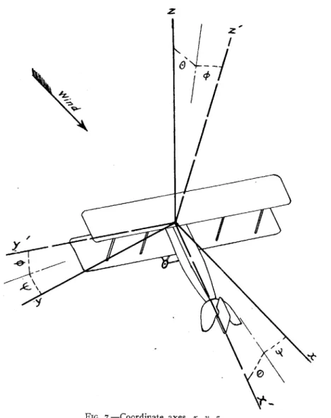
We shall adopt a notation similar to Bairstow's for the study of dynamical stability. The normal attitude of the aeroplane is its position when in steady flight in a straight line. We select rectan-gular axes with origin at the center of gravity and fixed in the
aero-7z
-9T 71 7-f 7-9 &.Y (7 7 _V1'
NO. 5 STABILITY OF AEROPLANES-HUNSAKER AND OTHERS
plane and moving with it in space. In the normal attitude, the axis of
x
is tangent to the trajectory of the center of gravity with its positive direction toward the rear. The axis of z is normal tox
andZ
FIG. 7.-Coordinate axes, x, y, z.
y in the vertical plane, and the axis of y horizontal and directed to the
left. The axes are shown in figure 7. As the aeroplane rolls, yaws, and pitches these axes move with it, so that
z
is no longer in the vertical plane of x, nor y horizontal.SMITHSONIAN MISCELLANEOUS COLLECTIONS
Let the aerodynamical forces along the axes x, y,
z
be denoted by X, Y, Z and expressed in pounds force per unit mass.' The momentsabout these axes are L, M, N in pounds-feet per unit mass. Angular velocities about the axis are p, q, r in radians per second. Let angles of pitch, roll, and yaw away from the normal attitude be 0,
4,
q inradians. Signs are positive in the directions xy, yz, and zx.
The radii of gyration about the axes x, y, z are KA, KB, K0 in feet.
The mass of the aeroplane is in in slugs. The products of inertia are D, E, F. Two are zero for reasons of symmetry, and one is small in ordinary aeroplanes.
In normal flight in still air, the apparent wind blows in the posi-tive direction of the axis of x. Let this velocity be produced by the forward velocity U of the aeroplane in normal flight. U is a negative number of feet per second.
Let small changes in velocity components along the axes x, y, z be u, v, w when any departure is made f rom the normal flying attitude. In normal flight it is assumed that the power available maintains the aeroplane at such a speed that the weight is sustained and also that the normal attitude is that proper for the speed.
9. EQUILIBRIUM CONDITIONS AND DYNAMICAL EQUATIONS OF MOTION
Let the inclination 2 of the flight path to the horizontal be 00. Since normal flight takes place in a straight line, i0= o0=o. There is no oscillation and p.=q=ro -o, and Lo=No=o.
If the propeller thrust T, be exerted in a line above or below the
center of gravity h feet, then
Mo = - Toh,
T,,= -gsin 00-X 0,
Zo=g cos 00.
In this aeroplane h = o, and hence Mo= o.
If any accidental cause slightly disturbs the normal attitude of the
aeroplane, the relative wind is no longer symmetrical and the aero-dynamical forces and moments are X, Y, Z, L, M, N.
In general, the aerodynamical forces and moments caused by the deviation from "normal attitude " depend upon the relative motion of the aeroplane through the air, which motion is defined by U, u,
v, w, p, q, r. Thus X=f(U, u, v, w, p, q, r) where the form of the function
f
is not known; and five similar expressions for Y, Z,L, M, N.
* Unit mass is the slug of 32.2 pounds weight.
2 Consider Oo positive for an upwardly inclined path as when climbing.
VOL. 62
No. 5 STABILITY OF AEROPLANES-HUNSAKER AND OTHERS In the theory of small oscillations u, v, w, p, q, r are small by hy-pothesis and we may expand X by Maclaurin's theorem, neglecting squares and products of these small quantities. Hence,
X = X0 + uX, + vXv + wXw + pXv + qXq + rXr,
Y= Y 0+uYU+vY,+WYFW+pYp+qYq+rYr,
and similar equations for Z, L, M, N.
Here X., Xv, etc., are the partial derivatives of X with respect to
u, v, etc., and are the rates of change of X with u, v, etc. That is,
XUax
a9x
There are, therefore, 36 " resistance derivatives " involved which are constants for the aeroplane and depend upon the arrangement of surfaces and their presentation to the relative wind.
Fortunately, for reasons of symmetry, 18 of these derivatives vanish, for example: X, Xp, X,. We then write:
X=X+uXu+wXw+qXq, M=M0+uMu+wMw+qZq, Z=Zo+uZu+wZw+qM, Y Yo+vYv+pYp+rYr, L=Lo+vLv+pLp+rLr, N=N+vN,+pNp+rNr.
The above expressions are only approximate if u, v, w, etc., are not small.
The equations of motion for a rigid body having all degrees of freedom, are: du dt +wq-vr=X+T0 +gsin( 0+), d+ (U+u)r-wp=Y-g sin 0, dt +vp-(U+u)q=Z-gcos(0+ ), d h dh- rh,+qh 8=rmL, dt A2 ph3+rh1=mM+hT, dt dh- qh 1 + ph2 = MN, dt where h= pK m-qF -rE, h2=qKm-rD - pF, h3=rK2m-pE -qD. 2I
SMITHSONIAN MISCELLANEOUS COLLECTIONS
But the products of inertia (relative to moving axes fixed in the body) D=F=o, because the aeroplane is symmetrical about the xz plane. Substituting the above expressions for h1, h2, h,, in the
equations of motion, and neglecting products of small quantities, we have:
u=X+ T,+gsin(O+), K, E drL
dt dt Init
dv + Ur= Y+g sin sin( 0+6) -g sin 4 cos(90+6),
K dq = h'T,
dtd
-wUq=Z-gcos(0+0), Ke =
r Ed N.
If we substitute for X, Y, etc., their values from the expansion in
terms of the first powers of u, v, w, etc., and observing that from the conditions of equilibrium,
M0+ Toh= To+Xo+g sin O0=ZO-g Cos 60=0,
we will have, making sin 4=$, sin &=&, sin 0=0, and cos 6=1.
d uXu'+wXw+qXq+g9 cos O, =qU +uZ.+wZ, + qZ7+g9 sin 60, dv
- = -rU+vYv+ pY+rYr +gg sin 60 -g cos 0,
K,2, =uM+wMw+qM,
K,2 K dp E dr'L =vL +pL + rLl,,PpL.
K2dr E dp
K'" dt mdt =vNv+pNp+rNr.
We here assume To a constant, or that there is no change of pro-peller thrust with small change in forward speed. With a motor in
" free route," if the machine speeds up, the propeller tends to race or
to speed up so that the slip shall be about constant, and hence the thrust is not materially changed. Since the forward speed (U u) is approximately equal to U, the thrust is approximately constant and equal to To.
We have also assumed that T, lies parallel to the axis of x. At very slow speed this is not exactly the case and T, has a small vertical component assisting in sustaining the weight of the aeroplane. At high speeds, T, is, however, usually parallel to x and the assumption
VOL. 62
NO. 5 STABILITY OF AEROPLANES-HUNSAKER AND OTHERS
that it always is so parallel is here made for simplicity. In any case
T, is eliminated by the conditions of equilibrium.
In the present investigation the normal flight path is assumed horizontal, or 00=. The product of inertia E is small for ordinary aeroplanes with the heavy weights fairly symmetrical above and below the axis of x. In view of the probable insignificance of E and the fact that E cannot easily be determined for an aeroplane by simple experiments, it is here neglected. In the simplified form the equations of motion then are:
du (a du =uXu+wXw+qX +g9, (1a) dw=qU+uZu+wZw+qZq, (ia) dv = -g-rU+vYv+pYv+rYr, (ib) dt K A =vLV+pLp+rLr, (ib) 2 di K=uM+wMw+qMq, (ia) K ct=vN+pATv+rNr. (ib)
It is seen that equations (ia) involve only the longitudinal motion or motion in the plane of symmetry xz of the aeroplane, -since p, r, v,
and p do not appear. Likewise, equations (ib) involve only the asymmetrical motion, lateral and directional, and do not contain
0, u, w, and q. The two sets may then be considered separately, the
former on integration giving the " symmetrical motion" and the latter the " asymmetrical motion."
.dO
Since do =q, equations (ia) may be written in terms of three
variables u, w, and 9 and their first derivatives. The " resistance derivatives "' X., X, Xq, etc., are constant coefficients. The three variables are each functions of the time, and the three equations at any instant of time must be satisfied by a concordant set of values of
u, w, and 0. The equations are, therefore, simultaneous and are
linear differential equations with constant coefficients.
Writing the operator D to indicate differentiation with regard to time or d
dt'
(D-Xu)u-Xww-(XD+g)0,
-Zu+ (D-Zw)w- (Zq+ U)DO=, (2a)
- Miu- Mww+ (KB2
D2- MD)= o.
SMITHSONIAN MISCELLANEOUS COLLECTIONS
The right-hand members of these equations are no longer zero if any wind gusts are assumed.' The complementary function may be found by the well-known." operational method " by algebraic solution for D. (See: Wilson's " Advanced Calculus," p. 223.)
The physical condition that the three equations shall be simul-taneous is expressed mathematically by equating to zero the
determi-nant
A formed by the coefficients of the variables u, w, and6.
Thus:D+XU, -X, -(XaD+q)
= -Zu, D-ZW, -(Z+U)D O.
-Mu, -Mw, (K D2 -MqD)
Expanding the determinant we obtain:
A1D4+B 1D3+C 1D2+D1D +E1=o,
where for abbreviation:
A =K ,
B - (Mq+X,jK+ZwK ),
_ Zw, U+Z Xu, Xq
+K
Xu, XMw,
Mq Mw, Mq B ZU, Z,XU, X, Xg Mu, (-) sin
60 D1
=-
Zu, Zw, U+Zq -g , MU, MW, Mqc X, Xw, cos 60 E1= -g Zu, Zw, sin 60. MU, MW, oThe solution of the biquadratic A for D is of the form: D=a, b, c, or d,
6o=K1ea +K2e0 +Kec'+ K4edt,
where K1, K2, K2, K4, K, . K12 are constants determined by initial
conditions. Solutions for
u
and w are similar.The condition for stability of motion is that
6,
u, and w shall diminish as time goes on. Hence, each of theroots
of the biquadratic must be negative if real, or, if imaginary,-must have its real part negative. This condition for stability may be applied without finding the constants K1 to K-,2 by solving only the biquadratic for a, b, c, d. Indeed, Bryan has shown that by use of Routh's discriminant the biquadratic need not be solved. The condition that a biquadratic equation have negative real roots or imaginary roots with real parts negative, is that A, B1, C1, D, E, and BCD,-AD 12-B, 2E, beeach positive.
' Loc. cit., p. i, i, footnote 3.
NO. 5 STABILITY OF AEROPLANES-HUNSAKER AND OTHERS In a similar manner the equations (ib) defining the asymmetric motion may be expressed as linear differential equations with con-stant coefficients.
Substitute D2
p for dp and Do for
p.'
Then:dt
(D- Yv)v+ (U- Y,)r+ (g- YvD)q0=0, - Lvv - Lr+ (K'D2- LpD )=0o, -Nov+ (K D -Nr)r -NvD=o, A2=A2D +BD 3+C 2D+D2D+E2=, where: B2= - YKK' - K'L - N,.K, C2= - LrNp + NrLp + KcLvY, +NrY,KA+N,UKA -(LvYpK' +NYrK2), D2 =Yv(LrNp-NrLv)+L,(UNv+gKC) -ULpNv
+ (N1rLp - LvYrNp+ LvYvNr - NYpLr), E 2=g(NvLr - LvNr).
As before, the condition for stability is that the real roots and real parts of imaginary roots of the biquadratic be negative.
io. CONVERSION TO MOVING AXES, LONGITUDINAL DATA
Horizontal flight at
o
incidence i of wing chord requires a speed of 112.5 feet per second, or about 77 miles per hour (see the characteristic performance curves). The normal attitude then has the axis of x parallel to the wing chord and horizontal. The axis z is vertical. For slow speed with an angle of incidence i of 12', a speed of 54 feet per second, or about 37 miles per hour, must be main-tained. In this case, the normal attitude has the axes x horizontal and z vertical, but the axes are entirely different from those used for the high-speed condition if they are considered with reference to the aeroplane. The axis of y is, however, the same in both cases.'Since we consider only the small oscillations, # and V/ are of the nature of infinitesimals, and hence compound vectorially as do p and r. Professor E. B. Wilson suggests the important simplification of the treatment given by Bryan or Bairstow due to making =P and =.r. They used angular
t dt yue nua
coordinates giving expressions for dt and dt in terms of p and r and the angles which are initially cumbersome but ultimately reduce to the simple form here given.
SMITHSONIAN MISCELLANEOUS COLLECTIONS
The aeroplane may pitch about its normal attitude. At any instant the angle of pitch is the angle 0 between the normal attitude axis of
x
and the new position of x. The axes, of course, pitch with the aeroplane. The axes are fixed by the equilibrium conditions and differ for each speed since each speed requires a different attitude.~2 I IT IT VT I K
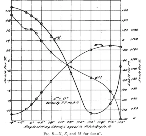
7ee -66 /47' t160 7./f' 0FIG. 8.-X, Z, and M for i=o'.
It was convenient to measure in the wind tunnel the lift and drift on the model referred to axes always vertical and horizontal. The corresponding forces along the moving axes x and z are readily obtained from:
Z'=L cos 6+D sin 0, X'=D cos 0-L sin 0.
Here L and D are pounds on model, 0 is angle of pitch, and Z' and X' are pounds force along the moving axes. X' and Z' are then con-VOL. 62
NO. 5 STABILITY OF AEROPLANES-HUNSAKER AND OTHERS 27 verted to full-speed full scale as usual and divided by the mass m in slugs to obtain X and Z in pounds per unit mass on the full-size aero-plane at the proper speed.
_A0
_ _ _ _
_ _ _ _ -lea
177,--.5
--- 0 '0
FIG. .- X, Z, and M for i
1*0
=30
The pitching moment full size is obtained from the observed model pitching moment about the center of gravity by an obvious manipula-tion. The moment is expressed in pounds-feet per unit mass and lettered M. -r I5 3 k
I-28 SMITHSONIAN MISCELLANEOUS COLLECTIONS For this aeroplane we have, for example,
44--
-/5-tO te' ' -/1Kt6 f/10-e
-6* - * -- O*.. ?
' * f 6
FIG. io.-X, Z, and M for i=6*. For this aeroplane we have, for example:
m = 50 slugs, 0 =0,
U -112.5 foot-seconds (high speed, 76.9 miles per hour),
i=o, normal attitude.
00 X Z M -4 -4 +10.66 + 11.00 + 50.2 -I -I + 9.62 + 21.18 + 23.2 O 0 + 8.98 + 32.06 + 23.0 +I +1 + 8.28 + 43-74 + 13.5 2 2 + 7-38 + 56.oo - 1-93 4 4 + 4.80 + 78.26 - 23.2 8 8 - 2.58 117.00 - 54.0 12 12 -10.68 140.6 - 75-3 16 16 - 8.72 149.00 -102.3 18 18 - 1.25 147.00 -158.2 VOL. 62 15. Jr0 15 /0 0 /
NO. 5 STABILITY OF AEROPLANES-HUNSAKER AND OTHERS
____ ___ - 20
-Vo
F/0 -. .- X, ,- - r = *
FIG. I i.-X, Z, and M for i = 12*.
e 56 .3,. 1' 2s
N
me k 10 10 -9 r-1 '6"7U= -54 foot-seconds (low speed, 36.9 miles per hour), 00=0, i=12', normal attitude.
X Z * M -4 -16 +1.87 - 3.0 +11.6 0 -12 +3-58 + 6.8 + 5.30 +4 - 8 +4.84 +17.4 - 5.32 8 - 4 +5.02 +26.6 -12.5 12 0 +4-38 +32.3 -17.4 16 4 +5.24 +34.2 -23.6 18 6 +6.78 +33.4 -36.5
When 0=0, note that Z, should equal 32.2 or g, a check on the table.
Curves of X, Z, M for the four speed conditions are given on figures 8, 9, 10, and ii. These curves are not " faired," but drawn
3
SMITHSONIAN MISCELLANEOUS COLLECTIONS
through the experimental points to show the consistency of the measurements and calculations.
ii. RESISTANCE DERIVATIVES, LONGITUDINAL
The longitudinal oscillations of the aeroplane are given by three equations of motion of 9, in which certain " resistance derivatives" are required.
The quantity X, is the rate of change of X with change of forward speed u. Since X varies as the square of the speed, X"= CU2
where C is some constant.
Then =2CU=: 2X0 =X. and ZU 2Z0
=
-, so that theseauT U _U U'
coefficients are readily calculated.
The derivatives XW,, Z,, M, represent the effect of a vertical
com-ponent of velocity w. The vertical comcom-ponent of velocity w acts with the horizontal velocity U to cause the resultant wind to have an inclination to the horizontal
AO=tan-1
U =57-3 U
when AO is a small angle measured in degrees. Hence Xw_ AX 57-3 AX w U A6 ' Z -57.3 AZ U AO ' M -57.3 AM U A0
The method practically substitutes the slopes ,
AO
' ofAOAO AO
the tangents to curves of X, Z, M, at
6=0o,
f or the actual curves. Wehave assumed AO small. If a curve be nearly a straight line, we may substitute the tangent for the curve without great error. Thus it may not always be necessary to assume AO very small. In fact, a range of from 5' to 8' is tolerable.
Since we assume M0 =o, the balance should be undisturbed by
change of forward speed. Therefore, M =o in all cases.
Note that a positive value of Mw corresponds to a curve of pitching moments giving statical stability or a righting moment. If M, is
positive it does not necessarily follow that the aeroplane will be dynamically stable, but if M, is negative, instability is of course certain. X, should be negative to indicate increased resistance for increase of forward speed - u. For stability, Zw should be large and
negative, indicating increase lift for larger angles of incidence and
vice versa. At stalling angles, Z,, tends to approach zero.
VOL. 62 30
NO. 5 STABILITY OF AEROPLANES-HUNSAKER AND OTHERS 31
12. DAMPING
The derivative Mq is the rate of change of pitching moment due to angular velocity, or rapidity of pitching q. For a pitch of velocity
dO
=q, there is a moment of qMq tending to resist such pitching.
This is the damping due to the horizontal stabilizer, elevator flaps, body, and all parts forward and aft of the center of gravity. The pitching takes place about the center of gravity. The damping is increased by a large tail and a long body.
The damping of a surface should depend on the area of the sur-face, the moment arm of that sursur-face, the linear velocity with which
it swings through the air (which varies also as the moment arm), and
with the velocity of advance. Thus: qMq-ql'U, where 1 is a linear dimension.
If we can measure Mq for the model at any wind speed, we may convert it to Mq for the full-scale aeroplane at its proper speed by multiplying by the fourth power of the scale and the ratio of aero-plane speed to wind speed. Naturally this is an approximate method, but it is the best available since full-scale tests for Mq are not practicable.
Similarly N,. and L, may be obtained from model tests. These refer to the damping of a yaw and a roll respectively.
In order to measure Mq, N,, and Lp a special oscillator was de-signed, shown in the photograph in figure 12. By setting the appa-ratus to oscillate in pitch, roll, or yaw the corresponding damping coefficients can be computed from the observed decrement. The pho-tograph (pl. I) shows the apparatus with model as used for pitching oscillations.
Let:
I=moment of inertia of all oscillating parts in slug foot units, m'=mass of all oscillating parts in slugs,
M.-momefit of air forces on model at rest, Mzzmoment of springs at rest,
KO-=additional moment of springs when deflected,
c=center of gravity of entire apparatus above pivot, feet, O=angle of pitch from normal attitude in radians,
dO
/A0 =damping moment due to friction,
dO
dO- damping moment due to wind on apparatus, dO
dO =damping moment due to wind on model,
kcn ' =t
SMITHSONIAN MISCELLANEOUS COLLECTIONS The equation of motion then is:
d2 dO
I dt2 * + dt +(K-cm')0+Mo-Ms=o.
But Mo=M by the initial condition of equilibrium. Let L=1o+-w+m;
then
af2o dO
then p d- + (K -cm') 0 -o.
Idt 2 +/1 dt +K c'60
The solution of this equation is well known to be:
0= Cel cos { t (K-cm')
-
/A+
,
where C and a are arbitrary constants. If time be counted when the amplitude of swing is a maximum, then cos I = I, and 0=0o, the initial displacement. Also if the number of beats be counted by observing the times for succeeding maxima, a plot of amplitude on time will have for its equation the simple form:
0=0oe
21.The coefficient IL is the logarithmic decrement of the oscillation and must be numerically positive to insure that the oscillation dies out with time.
The apparatus was fitted with a small reflecting prism by which a pencil of light was deflected toward a ground glass plate set in the roof of the tunnel. Nine lines spaced 0.2 inch were ruled on this plate. With the model at rest the beam of light was brought to a sharp focus on the line marked zero. By means of a trigger the observer started an oscillation of the model, and the spot of light was observed to oscillate across the scale. The time t was observed in which an oscillation was damped from an amplitude of 9 to an amplitude of I,
for example.
Then: loge 00 = t =loge 9, and knowing I and t, ft is calculated.
0 21
Preliminary tests showed that the same value of IA was obtained whether the timing stopped at 0=5, 4, 3, 2, or I.
Oscillation tests were made at five wind velocities varying from 5 to 35 miles per hour. The coefficient p. appeared to vary approxi-mately as the first power of the velocity.
Similar tests were made with the model for no wind to determine
,Lo, which may be said to be due almost wholly to friction and very
slightly to the damping of apparatus and model moving through the air.
VOL. 62
SMITHSONIAN MISCELLANEOUS COLLECTIONS
FIG. 12.-MODEL IN POSITION FOR PITCHING OSCILLATIONS ABOUT CENTER OF GRAVITY. L SPECTACLE LENS A, PENCIL OF LIGHT DEFLECTED TO SCALE ON ROOF