The Effect of Die Geometry on Extruded Paste Flow
for Continuous Production of Pharmaceutical Tablets
by Aditi Nagaraj
SUBMITTED TO THE DEPARTMENT OF MECHANICAL ENGINEERING IN PARTIAL FULFILLMENT OF THE REQUIREMENTS FOR THE DEGREE OF
BACHELOR OF SCIENCE IN MECHANICAL ENGINEERING AT THE
MASSACHUSETTS INSTITUTE OF TECHNOLOGY FEBRUARY 2011
C2010 Massachusetts Institute of Technology
ARCHIVES
AASSAWWU,.-ETT'S INSTITUTE-LB TEC A SLOGYOCT 20 2011
OT3PRIES
Signature of Author:Department of Mechanical Engineering January 14, 2011
Certified By:
Accepted By:
Professor Jung-Hoon Chun
Professor of Mechanical Engineering Thesis Supervisor
Prof. John H. Lienhard V Collins Professor of Mechanical Engineering Chairman, Undergraduate Thesis Committee
The Effect of Die Geometry on Extruded Paste Flow
for Continuous Production of Pharmaceutical Tablets
by Aditi Nagaraj
Submitted to the Department of Mechanical Engineering On January 14, 2011 in Partial Fulfillment of the
Requirements for the Bachelor of Science in Mechanical Engineering
Abstract:
The design of an extruder-based continuous tablet forming process of a sample active pharmaceutical ingredient (API) and ethyl acetate requires a device to form and compress the tablets. The flow of the wet extrusion is driven by the pressure head generated by the torque of the screws; the minimum pressure head is dictated by the head loss across the exit die. Since the API powder blend and ethyl acetate solvent form a highly filled suspension paste, the liquid phase tends to flow at a different speed than the solid when the driving pressure changes. As such, the three die geometries, straight, curve, and elbow, resulted in average steady state liquid mass fraction of 0.179 ± 0.005, 0.249 + 0.01, and 0.200 ± 0.009 respectively, although the
increases in mass fraction do not correspond to increases in pressure drop across the die. This experiment tests a particular tablet forming process, which involves using the pressure of the extruder to squeeze out the liquid content of the tablets during forming. The occurrence of liquid phase migration after this tabletting process is confirmed in each die tested. The extent of
variation in liquid content shows a 30% increase for the straight die, a 50-200% increase for the curve die, and 50-150% increase for the elbow die. These results suggest that a tablet forming device should not use the pressure of the extruder, due to the complications of paste flow.
Thesis Supervisor: Jung-Hoon Chun Title: Professor of Mechanical Engineering
Author's Biographical Note:
I will graduate from MIT this February 2011 with a dual degree in Mechanical Engineering and
Environmental Engineering. In fall of 2011 1 plan to pursue a Masters/PhD in Mechanical
Engineering. Before that, I will spend the first six months of 2011 in Munich, Germany, working for BMW on new sensor and software technologies for safety and comfort. I was born in
Bangalore, India, but grew up in the Silicon Valley in California. I would like to thank my parents for inspiring me to pursue engineering and for all their help on my journey so far.
Acknowledgements:
This thesis would not have been possible without the guidance and mentorship of the following people:
Professor Jung-Hoon Chun, who encouraged me to think critically and understand every complexity of the tablet forming process, while providing plenty of advice along the way.
Aron Blaesi, who was very helpful in discussing fluid mechanics theory and devising a rigorous experiment to test my theory.
Dave Dow, Patrick McAtamney, and William Buckley, whose knowledge of fabrication
techniques and patience for my questions made building the device go smoothly.
Salvatore Mascia, Erin Bell, Paul Madenjian, and Ashley King, who were always eager to help
me understand chemical engineering principles and testing techniques for the wet extrudate. A special thanks is necessary for their patience and assistance when running the extruder and collecting samples.
Table of Contents
Abstract ... 2
A uthor's B iographical N ote ... 3
A cknow ledgem ents ... 3
Table of Contents ... 4
1. Introduction ... 5
2. Background 2.1 Functionality of an Extruder ... 7
2.2 Steady State O peration ... 9
2.3 T ablet Form ing ... 10
2.4 Liquid Phase M igration ... 12
3. Method and Materials 3.1 Designing the Extruder Attachment, Dies, and Molds ... 14
3.2 Specifics of Wet Extrusion ... 18
3.3 Measuring Mass Fraction of Liquid and Mass Flow Rate ... 19
4. D ata and D iscussion ... 22
5. C onclusion ... . 3 1 B ibliography ... 33
1. Introduction
In the pharmaceutical industry, tablets allow for standard dosing and delivery of the active pharmaceutical ingredient (API). As such, the tablets must have a consistent and uniform weight and active ingredient content, in addition to withstanding a reasonable level of yield and shear stress. The manufacturing process for a tablet depends on the chemical composition of the API (Hienstand 2003). APIs are routinely blended with a variety of excipient powders, which change overall binding, tensile and shear strength, viscosity, and granulation of the blend, in order to facilitate both the tablet forming and digesting process.
Certain powder blends require a liquid solvent to provide additional binding prior to dosing and compaction. The liquid-powder material is mixed, dried, and granulated. The aim of the wet granulation process, including the extra stage of mixing, is to produce pellets of uniform density, size, and API content to aid in the dosing process (Hienstand 2003). However, as suggested by Benbow and Bridgwater, the wet granulation process must be done in batches, which slows down the downstream tablet forming process (Benbow 1993).
In this investigation, we aim to assess the viability of replacing the wet granulation stage with a continuous process. We propose the use of an extruder to evenly mix the powder blend and liquid solvent. In order to dose and form the tablets, the extruder is fitted with a die which forms the wet extrusion into a cylinder. The molding process is directly coupled to the mixing and extruding process; the extrudate from the die flows into a set of tablet molds, which are filled using the pressure force generated from the paste flow. The molds also serve to dose the API.
Testing of the device showed that the die geometry affects both the steady state operation of the extruder and the consistency of the API content of the final tablet. Understanding why and
how these factors change is helpful in future development of a continuous, extruder-based tablet forming process. The results of this study also provide insight as to the nature of a sample API blend.
The experiment involves using three dies of varying geometries to mold tablets. Since the extruder must generate a pressure gradient to press the flow through the die, the flow rate of the two-phase material is dependent upon the pressure head loss unique to each die. Furthermore, the changes in pressure that occur during the molding process cause the system to deviate from steady state, which can result in highly unpredictable mass flow rates and separation of the liquid and solid phases. A discussion of the interplay between the extruder and the two-phase flow considered can be found in Chapter 2. In this experiment, the mass flow rate and the fraction of the API in the flow are both measured before and after the tablet forming process. Chapter 3
outlines the experimental method used to collect the data. Using this data, we can determine the steady state flow rate and density, or mass fraction, of liquid of the tablets for each of the three die geometries. The implications of these results are discussed in Chapter 4, along with some comparison to theoretical explanations from paste flow mechanics and other pharmaceutical studies. Finally, the die geometry experiments and considerations are summarized in Chapter 5.
2.1 Functionality of an Extruder
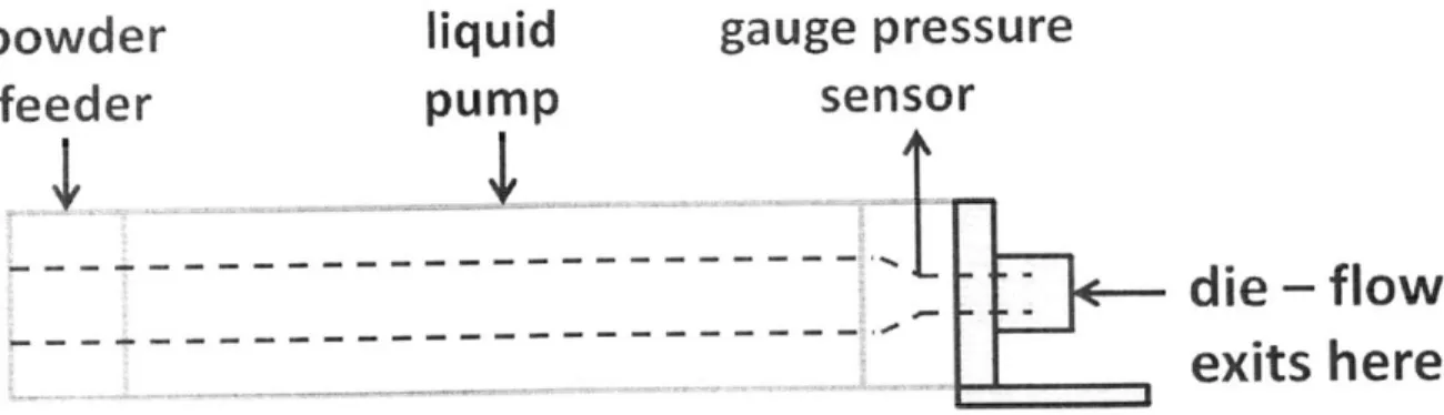
The extruder used in this experiment consists of a barrel enclosing two co-rotating and interlocking screws that serve to both mix and transport material axially, by squeezing the material between the gaps of the screws. The blended powder is added at entrance of the barrel,
while the liquid solvent is added approximately halfway down the length of the barrel. Diagrams of the functionality of co-rotating extruders are presented in Figures 2.1.1 and 2.1.2.
~-
r
Figure 2.1.1: Feed In Mechanism for Co-Rotating Extruder (Benbow 1993)
powder
liquid
gauge pressure
feeder
pump
sensor
pump
-
---
---
- --- --- --- ---F-I
die
-
flow
exits here
Figure 2.1.2: Diagram of Co-Rotating Extruder -dashed lines indicate interior
& X 1 Tj C n' t e
ii: cnoviad f,-oq-t
At steady state operation, the extruder's screws exert a torque on the material to generate a pressure gradient that drives flow out of the die. By applying the law of conservation of energy to the barrel of the extruder, Benbow and Bainbridge determine that the pressure gradient, P, is a function of the shape of the die, given by:
L
P = 2 * ln-"+4-
(1)D D
where c- is the uniaxial yield stress, Do is the diameter of the barrel, D is the diameter of the die, -u is the wall stress in the die, and L is the length of the die (Benbow 1993). The first term
represents the entrance loss as the diameter of the extrusion in the barrel must decrease to the diameter of the die while the second term is a measure of the pressure head loss due to friction. It is noted that the friction caused by the walls of the barrels is not accounted for by this equation. For viscous, Newtonian liquids, such as ethyl acetate, yield and wall stress are both proportional to velocity of the flow.
Furthermore, volumetric flow rate,
Q,
is determined by the displacement of the screws, rather than by the input flow rates of powder and liquid. Van Der Goot finds that the volumetric flow rate isQ
= NVc
(2)where N is the screw rotation speed and Vc is the volume between a set of screw threads and the barrel wall (Van der Goot 1996). From Equations I and 2, we can see that the screw speed must be optimized for a specific wet extrusion formulation, given the motor power output and extruder die geometry. In actual operation, the screw speed is set well below this optimal level, to absorb increases in pressure and to minimize strain on the material.
2.2 Steady State Operation
Operation of the extruder is contingent on the system reaching steady state. In melt extrusion or other single polymer input extrusion, this steady state is simply dependent on the input mass. The wet extrusion system is complicated by the addition of an input liquid stream, which must combine to form a paste.
Once the volumetric flow rate is set by the screw rotation speed, the input solvent and solids mix to form an equilibrium output density (Benbow 1993). However, in practice, non-constant volumetric and mass flow rates are observed, while density still remains non-constant. In steady state, energy of the paste system is conserved. Thus, the first law simplifies to:
2 1 2U o~g 1
'4screws = ?in [Patm + Pin v + Pingz - Ikut Patm + pout + pout gz (3)
where Wscrcws is the work done on the paste control volume, 111 is the mass flow rate of the paste,
Patm is the pressure head, pgz is the gravimetric head, with z being the height difference between entry and exit, and 0.5pv2 is the velocity head. The densities, p, of the entering and exiting flows
are different, as the exit density depends on the fraction of liquid in the paste mixture. The mass flow rate out is dependent on the mass flow in, the density of the exiting flow, and the work done on the system by the screws. The mass flow out is not equivalent to the sum of the mass flow of the powder and liquid entering the system; the extruder serves to balance out the input masses and their densities.
Realistic operation of the extruder must account for unsteady inputs. In this case, the input of the powder and liquid fluctuate around the level they are set at, while the densities are
constant. As such, the exit mass flow also fluctuates, to continue smoothing the exit density to a constant value (Benbow 1993).
Furthermore, the torque of the screws varies with the shear stress of the material, which is indicated by the density of the combined flows. In equilibrium, the work done by the screws, which is determined by the pressure drop that the extrusion must overcome, then drives a certain density of flow out. This suggests that different pressure heads (from different die shapes or otherwise) and screw speeds will cause different equilibrium densities in the exit flow.
Thus, steady state operation of the extruder is only measured by the consistency of the density of the exit flow. A uniform density means that any sample will have an equal ratio of liquid to solid. Given the unsteadiness of the input mass flows, dosing the API for each tablet must involve alternative techniques to time-based filling of molds or granulation of the extrudate.
2.3 Tablet Forming
Using wet extrudate as the material source for the tablet forming process causes some challenges. First is the liquid content, which must be dried from the formed tablet to keep their form. Second, the exit mass flow rate is not constant, so the tablet forming process must find an alternative to filling molds based on time. Finally, the wet granulation process also runs into the problem of liquid phase migration. During the operation of the extruder, any changes in pressure or changes in die shape result in a change in the liquid content of the mass flow.
These challenges dictate a very specific tablet forming process. Even though the density of the tablets (or ratio of solid to liquid) is constant, the variable mass flow rate makes it difficult to determine the API content without limiting the mass flow rate. We chose to use volume based molds, since the tablets are of known density and liquid mass fraction. As the molds are filling,
the pressure in the extruder increases, because of the reaction force of the bottom face of the mold. In this investigation, this pressure change created by filling the mold was unavoidable.
The liquid content of the tablets is due to porous gaps in the solid matter. As the tablets dry, a network of solid matter remains. If the liquid content of the initial tablet is too high, these tablets will simply crumble, since the gaps will be too large for the solid matter to remain cohesive (Benbow 1993). There are two options to overcome this: compressing the tablets either during the drying process or during the tablet forming process. The advantage to compressing during the tablet forming process is that the machinery is consolidated and the tablets keep their form well since they are still in their molds. We chose to use the compression of the extruder flow in this investigation. In this situation, the continuous flow of the extruder as the molds are being filled causes the liquid to be squeezed out of the porous gaps in the solid matter, to be replaced with additional solid matter. This procedure can cause large spikes in the pressure of the extruder, but higher pressure leads to more compressed pills, which lowers drying time and increases the tensile and yield strength of the pills.
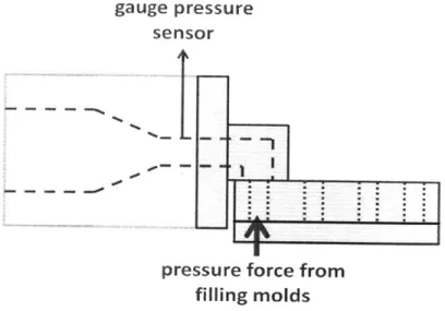
Thus the tabletting process is inherently not a steady state process, so operation is somewhat unpredictable and uncertain (Benbow 1993). Theoretical and quantifiable studies on unsteady operations of an extruder are scarce, and literature only offers operational guidelines rather than absolutes to adhere to. As seen in Figure 2.3.1, the variable pressure force acting on the mass flow changes the conservation of energy detailed in Equation 3.
gauge pressure
sensor
M
-.
pressure force from filling molds
Figure 2.3.1: Forces acting on Paste Mass Flow in Die Region
The nature of steady state operation is that it is sensitive to outside forces. However, in an extruder, this has different implications, which can alter the flow rate to an inoperable extent. Liquid phase migration, discussed in more detail in Section 2.4, is consistently observed using this method of tablet forming. The pressure changes from the molding process are studied in this experiment, to determine the limits to compression and to reconcile the advantages to using the flow of the extruder to compress the tablets. However, a molding process coupled to the
extrusion flow is not necessary so the pressure spikes can be avoided, but the non-constant mass flow rate must be dealt with in order to achieve consistent dosing and sizing of the tablets. 2.4 Liquid Phase Migration
A key challenge in developing an extruder-reliant process for the solvent-powder flow is
the instability of paste flow. The two phases of the paste flow, liquid and solid, must be considered separately to understand the dynamics of the system. The driving pressure force dictates the flow rates of the liquid and solid separately (Benbow 1993). Once these flows reach
steady state, the paste is at its equilibrium mix of liquid and solid. As discussed in previous sections, changes in pressure will change the liquid content of the mix. This phenomenon of liquid phase migration is studied separately by both Benbow and Mascia, who suggest that the difference in viscosities of the two phases causes the liquid to be more influenced by the pressure changes (Mascia 2006). Benbow states that excessive pressure acting on the paste flow will cause the liquid to seep through the gaps in the solid matter (Benbow 1993).
In terms of this experiment, liquid phase migration occurs during the molding process, because of the change in pressure across the die and mold. In fact, the pressure increase in the molds actually causes an inverse pressure gradient, which leads to the reversal of liquid flow. While the flow is compressing the tablet, the gaps in the tablet that were once filled with liquid are replaced by solid, squeezing the liquid back into the extruder region (Benbow 1993).
In terms of the manufacturing process, liquid phase migration can be overcome, for the paste flow can return to its steady state composition over time. To describe an occurrence of liquid phase migration, Mascia et al. has studied the severity of variation in liquid content over the course of higher applied pressure (Mascia 2006). Understanding the extent to which the liquid changes along with the time it takes for the liquid movement to occur is key to developing a manufacturing process specific to an API/solvent blend and any tablet forming mold. Drying the liquid solvent out of the tablets can take up to a week for the solvent used in this experiment. As such, any tablets formed with higher liquid content will need to be identified. The design of a device must minimize the change in liquid fraction, as excessive phase migration of the liquid back into the barrel of the extruder can disrupt the flow rate of the powder.
3. Characterizing Flow of Different Die Geometries
To determine the steady state flow rate of each of the die geometries and the quality of the resulting tablets, the mass of the extruder flow over discrete time intervals was measured before, during, and after the tablet forming process. Since the ethyl acetate solvent used as the liquid phase of the wet extrusion was chosen for its rapid evaporation rate, the mass of the samples after two days of drying can be used to determine the fraction of liquid of the flow.
3.1 Designing the Extruder Attachment, Dies, and Molds
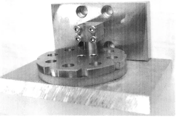
The device designed for the tablet forming process was specific to the Leistritz Nano 16mm Twin Co-Rotating Screw extruder. A base plate was fixed to the end of the extruder barrel, to serve as a mounting face for different exit dies and mold plates. The base plate was fabricated from stainless steel 303. A picture of the setup is shown in Figure 3.1.1.
From Equation 1, anything beyond the main barrel of the extruder is considered to be the die region. Therefore, to isolate the effect of die geometry on the mass flow rate and liquid phase migration, the experimental dies were designed with equal length and diameter, but with variable head loss coefficients. The first die used was straight, with L = 1 in. and D = 7/16 in. This die
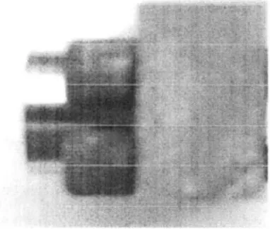
was fabricated out of stainless steel 303 and is shown in Figure 3.1.2.
Figure 3.1.2: Close Up of Straight Die
The second die had a 900 bend with a radius of curvature of 0.63", giving a curved elbow shape. By increasing the radius of the bend, the die has a lower head loss coefficient than that of the elbow (Cravalho 2005). The arc length of the curve was set to be 1 inch, in order to keep die length consistent across each geometry. To fabricate the curved die, a channel was milled out of two square blocks of stainless steel 303. The two blocks were then aligned using two dowel pins and clamped together. One half of the die is shown in Figure 3.1.3, to show the shape of the curve.
Figure 3.1.3: Inner View of Curve Die
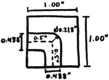
The final die had a sharp 90' bend, with a die length of 1 inch and diameter of 7/16 of an inch. The die was fabricated out of a block of stainless steel 303. The holes for the die were drilled from two perpendicular block faces, using a 7/16" ball end mill to round out the connecting elbow. The elbow die is shown in Figure 3.1.4 below, along with a diagram of its internal measurements.
I .00
L.0
Figure 3.1.4: Picture of Elbow Die Figure 3.1.5: Cross Cut of Elbow Die
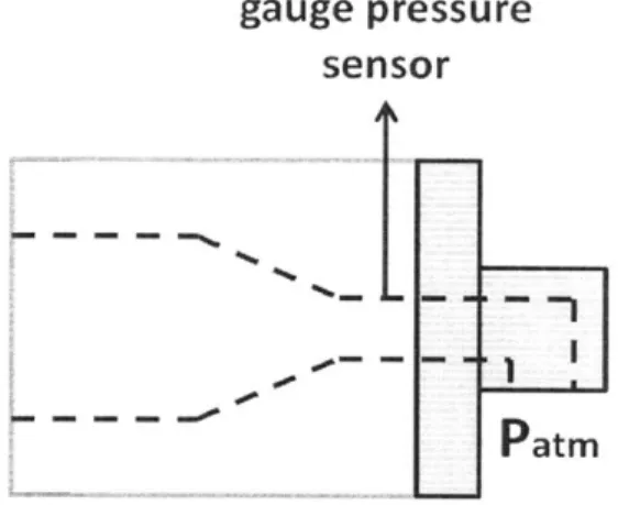
As discussed in Chapter 2, the pressure drop across the die dictates the density and
fraction of liquid in the exiting mass flow. Thus, the steady state gauge pressure was measured in
16
the section of the extruder at the end of the screws, as shown in Figure 3.1.6. We expect each die to generate a different steady state pressure at this point, due to variable head loss coefficients.
gauge pressure
sensor
Patm
Figure 3.1.6: Pressure Drop across Die
Several circular molding plates were also fabricated, by waterjetting plates of stainless steel 303. The molds consisted of a solid bottom plate and a top plate with eight circular holes of
7/16" diameter for the tablets. The molds were fixed to the baseplate with minimal space
between the top surface and the end of the die. Each mold could either be vertical or horizontal, based on the die used. The molds were rotated around a center pin to fill each cavity. The
pressure in the molds could not be measured reliably, so the pre-die pressure reading was used to guide the molding process. Figure 3.1.7 shows a diagram of the molds.
top view
F-F-I I
Li-solid bottom plati
mold cavities
top plate
e
Figure 3.1.7: Diagram of Mold Design
3.2 Specifics of the Wet Extrusion
The design of this experiment is highly specific to the properties of the API and solvent. The API and binder were pre-blended using low shear methods. The powder blend was then added to the extruder via the Schenck Accurate DP-4 Gravimetric Feeder at a rate of 40 grams per hour.
The ethyl acetate solvent was simultaneously added to the extruder at a rate of 1.5 mL/min at the position shown in Figure 2.1.2. The choice of ethyl acetate as a solvent was for its high volatility and viscosity. Since the tablets must be dried to remove all traces of solvent, the high volatility ensures a relatively short drying time. The dynamic viscosity of ethyl acetate is 4.26* 104 Pa*s, around three times that of water. The high viscosity ensures a low Reynolds number flow and also mitigates liquid phase migration (Mascia 2006). The liquid content of the wet extrusion was determined through experimental testing, by finding the lowest liquid fraction
.0 0.4375" 3.0
s ve3.00"
blend that was still malleable (Benbow 1993). The liquid solvent serves as a transporting agent, to reduce stress on the powder by the screws.
Through prior tests, the extruder screw speed was set at 125 rotations per minute. Screw speed should be optimized for die geometry, since the extruder operates at a different pressure for each die. For the purposes of this experiment, screw speed was kept constant, as changes in screw speed could negate any differences in flow characteristics between the dies.
In order to maintain a standard molding process, each tablet cavity was filled until the pre-die pressure measured on the extruder increased to 10 psi above the average steady state pressure. This was set in order to achieve some compression of the tablets. By pressurizing each tablet mold to the same level while holding the volume of each mold constant, we ensure an equal amount of powder blend in each formed tablet as the new pressure gradient dictates.
3.3 Measuring Mass Fraction of Liquid and Mass Flow Rate
In order to measure the effect of each die on the flow rate of the extruder, we ran the
extruder with the same powder blend, flow rates, and screw speed with each die attached to the same base plate shown in Figure 3.1.1.
To measure the mass flow rate, we took two 15 second samples every minute by cutting the extrusion as it came out of the die. This procedure was conducted for 10 minutes. Once the exit flow reaches steady state, we formed 24 tablets using the tablet forming process described in Section 2.3. After this, samples were taken for an additional 15 to 20 minutes, to allow the system to return to steady state. The tablet forming process was repeated for another 24 tablets. Samples were taken again as the system returned to steady state. This five-stage process was run
for each of the three dies. To verify the steady state time for the curve and elbow dies, the first three stages were repeated, extending collection time post-tablet forming.
The tablets were massed immediately after collection and two days after collection, using a Metter Toledo AX10S Delta Range scale. Each sample was weight using a precision of 102 milligrams. To compare liquid content, we measured liquid mass fraction of the pills, X, over time. This was calculated by determining the mass lost from the pills over a two day drying period, as follows:
X = -m(4)
where mi is the mass of the sample initially and mf is the mass of the sample after two days of drying at atmospheric pressure and room temperature. We expect the liquid content of the dies with higher head loss coefficients to be higher, since the increased pressure drop will drive the liquid through the solid at a faster rate.
Furthermore, liquid phase migration should occur sooner or be more pronounced in the dies with higher head loss coefficients, like the elbow and curve die. The occurrence of LPM will be indicated by sudden increases in liquid mass fraction after the tablet forming process. This is
expected to occur for every die, but will be more extreme in the 90' bend dies.
In this experiment, we are interested in determining the steady state density of the mass flow. However, there are no consistently reliable methods to measure the volume of the samples, since the solid is a compressible, particulate matrix; therefore, density is difficult to calculate. Instead, we use the mass fraction of the samples as a substitute for the density, from the
interested in observing liquid phase migration, which is indicated by an increase in liquid content over a certain segment of samples. The discrete mass flow rate and change in mass fraction over time are the flow characteristics we are interested in, for each die throughout the steady state and molding processes discussed above.
4. 1 Data and Discussion
The results of these experiments are presented in Table 4.1.1 below. The equilibrium mass fraction varies between the different dies, although it is not correlated with the head loss coefficient or the experimentally measured pressure drop across the die. Notably, the curve die, which has the median pressure drop, also has the highest liquid mass fraction and the highest mass flow rate. This suggests that the pressure drop across the die affects the liquid mass fraction, but not in a predictable way.
The steady state mass flow rate is measured here in milligrams per second. The
confidence interval is a significant fraction of the average mass flow rate, and such variance is not acceptable for pharmaceutical standards, which have small tolerances on product content. This necessitates the use of molds to produce tablets of consistent solid content, which is shown in Table 4.1.2.
Table 4.1.1: Steady State Flow Characteristics
Equilib. Liquid Steady State Mass Estimation of Die Geometry APss (psi) Mass Fraction Flow Rate (mg/sec) Steady State Time
Straight Die 15.2 0.5 0.179 0.005 14.7 3 - 10 min
Curve Die 16.5 ± 0.4 0.249 0.01 20.70 + 2 ~ 25 min
Elbow Die 19.6 t 0.4 0.200 0.009 13.68 2 Disturbed by LPM
Figures 4.1.1 through 4.1.3 show that mass flow rate for each die is indeed unsteady, even before tablet forming, while mass fraction of liquid does reach an equilibrium level over time. The data points were calculated by dividing the sample mass by the time they were collected; the time for tablet forming was recorded directly from the extrusion.
4 U
steady state
35 after tablet forming s after tablet forming 2 30 x tablet forming tablet forming 2 25 - -20 - -4 15 - -* ... ... . 10 5 - -0 1.. .. --60 70 time (minutes)
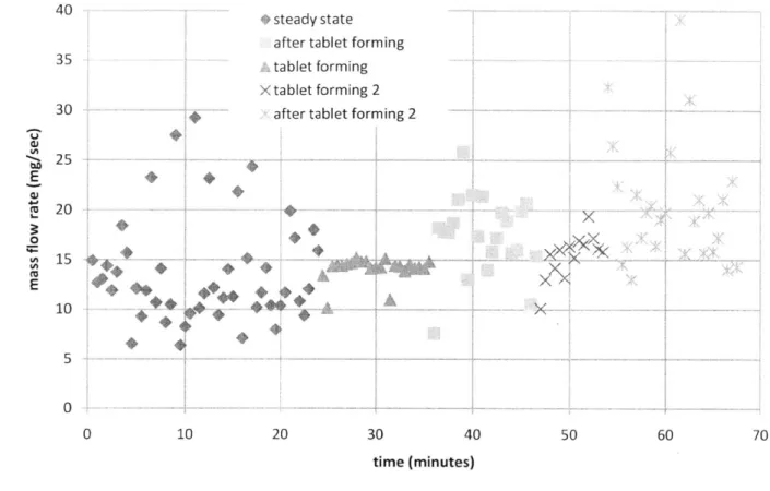
Figure 4.1.1: Straight Die Mass Flow Rate
30 * 25 4 20 15 10 -A 5 0 * steady state after tablet forming
-tablet forming
X tablet forming 2 after tablet forming 2
30 4(
time (minutes)
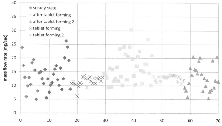
Figure 4.1.2: Curve Die Mass Flow Rate
400 steady state after tablet forming
35tablet formng
Xtablet forming2
30 after tablet forming 2
225 E r20 0 X
Sx....
10*
..
.
...
5 0 - ' -. ..--.- --.- --. 0 10 20 30 40 50 60 70 time (minutes)Figure 4.1.3: Elbow Die Mass Flow Rate
Generally, the samples taken prior to any tablet forming are more concentrated around an average; this is where the estimation of steady state mass flow rate in Table 4.1.1 is calculated from. However, after tablet forming, the system behaves erratically, showing no time based trends or a definitive return to steady state. We can conclude that mass flow rate fluctuates even in steady state and is highly susceptible to outside forces.
As discussed in Chapter 2, the extruder should generate consistent density paste in steady state. The equilibrium mass fraction is found to be 0.179 ± 0.005 for the straight die, 0.249 ±
0.01 for the curved die, and 0.200 ± 0.009 for the elbow die. The variance in liquid mass fraction
of the samples is small, suggesting the extruder has reached steady state. This idea is echoed in Figures 4.1.4 through 4.1.8, which show relatively consistent mass fraction measurements prior
to tablet forming. The time the system takes to return to steady state after tablet forming is estimated using this data.
*steady state after tablet forming
A&after tablet forming 2
X tablet forming tablet forming 2
time to steady state
X
XX
0.5 0.45 0.4 0.35 0.3 0.25 0.2 0.15 0.1 0.05 0Figure 4.1.4: Straight Die Liquid Mass
30 40
time(minutes)
Fraction during the Tablet Forming Process
The time to steady state is estimated by finding the start of a section of samples with minimal variance. With the curve and elbow dies, the time between two tablet forming stages was too short to conclusively show a return to steady state flow rate as shown in Figures 4.1.5 and 4.1.7. Thus, the experiment was repeated, shown in Figures 4.1.6 and 4.1.8. However, we found that the liquid phase migration that occurred after these tablet forming processes was so extreme that the liquid had travelled back to the feeder region of the screws. This suggests either that the pressure during the molding process was too high or was applied for too long.
Liquid Phase Migration
As expected, the pressure measured in the pre-die area does spike during the tablet forming process. We captured the average peak pressure measured on the extruder during the molding process; since the pressure within the die is unknown, we cannot determine the pressure drop across the die during tablet forming. These results are represented in Table 4.1.2. The molding pressure of the two 90' bend dies is much higher than that of the straight die.
* steady state after tablet forming tablet forming
X tablet forming 2 after tablet forming 2
.4 4 4
I
Liquid Phase Migrati on L~.xx
4* * .4 .4xx
x
x
xt
30 40 time (minutes)Figure 4.1.5: Curve Die Liquid Mass Fraction during the Tablet Forming Process
0.4
+ curve steady state
curve tablet forming process curve post tablet forming
A I
I'
imetb
steadst
0 -.. -. -. -0 5 10 15 20 25 30 35 40 45 50 time (minutes)Figure 4.1.6: Curve Die Liquid Mass Fraction - repeated to determine steady state settling time
0.45 0.4 0.35 - . 0 Z 0.3 U (A ,A0.25 E -0 '5 0.2 0-0.15 0.05 0 0.35 0.3 0.25 0.2 0.15 0.1 0.05 ... ... . ... -A,
0.45
0.4
0.35
* steady state after tablet forming tablet forming
X tablet forming 2 after tablet forming 2
Li cLui Fhseai Mi grOti on 0 0.25 - .. .. E 0 0.2 0.15 0.1 -0.05 0 3 B me (minutesi0
Figure 4.1.7: Elbow Die Liquid Mass Fraction during the Tablet Forming Process
0.5 0.45 a 0.35 0 S0.3 CA ,0.25 E :2 0.2
8elbow steady state
-0.15
elbow tablet forming process
0.1
A elbow post tablet forming process
0.05 Liquid Phase Migrat ion A
I~~~
. 15 time (minutesTFigure 4.1.8: Elbow Die Liquid Mass Fraction - Repeated to determine steady state settling time
...
.
...
.
...
...
X
X
X
Figures 4.1.4 through 4.1.8 and calculations represented in Table 4.1.2 do show that each die produces tablets that have consistent masses and low liquid content, at least compared to the steady state samples. This was the aim of designing a tablet forming process that included
compression. However, issues arise with the flow of the extruder post-tablet forming. It is highly inconsistent and sometimes even unstable. As with Mascia study on ram and barrel extrusion, liquid phase migration is identified when liquid content goes beyond the variation of steady state liquid content (Mascia 2006). Liquid phase migration has always occurred after the tablet
forming process, although it is sometimes not extreme or pronounced, so the disruption of flow is avoided. This is especially the case with the straight die: the lower molding pressure forms satisfactory tablets while still allowing the system to settle back to steady state.
This higher pressure and time of tablet molding leads to much lower liquid mass fraction of the tablets than in the steady state scenario. In the case of the elbow die, even though the molding pressure is not as high as that of the curved die, the low liquid content and large mass of the tablets suggest that the liquid in the tablet cavities is being displaced back into the extruder barrel while the tablets are being formed, causing liquid phase migration to appear later in the process. This accounts for the quick onset of liquid phase migration, which is measured as the time the tablet molding pressure acts as an external force on the system.
Table 4.1.2: Key Characteristics of Tablets and Tablet Forming Process
Average Molding Average Average Liquid
Die Geometry Pressure (psi) Mass (mg) Mass Fraction Onset of LPM
Straight Die 25 3 181.9 ±7 0.164 ±0.02 20 min
Curve Die 40 ±5 228.8 ±6 0.188 ±0.01 < 11 min
Quantifying the change in liquid content shows a 30% increase for the straight die, a 50-200% increase for the curve die, and 50-150% increase for the elbow die in liquid post-tablet forming samples. It is certain that liquid phase migration will occur, since the liquid in the tablets is being squeezed out and the higher pressure during tablet forming is causing the liquid to move faster or reverse. However, the onset and extent of liquid phase migration is not consistent, even in repeated experiments for the curve and elbow die. Thus, any characterization of liquid phase migration seen in this experiment is only qualitative. It seems that the extremity of liquid movement within the barrel of the extruder builds up, which makes sense through the mass continuity equation. Figure 4.1.7 shows that the second stage of tablet molding produces more compressed tablets, followed by a sharp increase in liquid content. Indeed, liquid content of samples post-tablet forming is much higher for tablets with low liquid content; this conclusion can also be deduced from conservation of mass.
The two repeated experiments confirm liquid phase migration in the elbow and curve dies. The mass fraction of liquid is 0.187 ±0.007 for the curve die and 0.30 1 ± 0.01 for the
elbow die. With the curve die, the liquid phase travelled back to the feeder region, mixing with the powder entering and causing bridging, which stopped additional powder from entering the extruder barrel and essentially halted the extrusion. The bridging and stopping of the extrusion also occurred with the elbow die, although the liquid fraction is much higher, which does not provide insight as to why the bridging or liquid migration occurred.
It is clear that, while the extruder's behavior is mostly understood and expected, some of these results cannot be well explained. For example, the figures of mass fraction show the entirety of the extruder's operation, once paste began to flow from the exit. The samples start with 10 minutes (at the minimum) to allow the flow to reach steady state. Once liquid fraction
was determined, the data showed the flow took anywhere from one minute to the entire 10 minutes to settle to a steady state liquid fraction. This might be that the realistic liquid content is not as steady as theory suggests. There might be additional factors, like the feed rate of powder, which fluctuates, and changes in shear forces along the barrel. Indeed, the shear force depends on the instantaneous liquid content of the mixture, as shear is much higher on the powder than on the liquid, so this could be a plausible explanation for the lack of a clear connection between
liquid content and die geometry.
Additionally, the liquid content may not be ideally measured, as the ethyl acetate dries immediately after leaving the extruder. The data points can then be compared to each other, as each of them are exposed to the environment for the same amount of time. However, this makes it impossible to conclude whether the mass flow rates are conserved in the system; applying conservation of mass to the system, Equation 3, gives us a theoretical mass flow rate that is much higher than what is observed.
5. Concluion
The results of this experiment suggest that a tablet forming process that uses the pressure of the flow to create low liquid content, densely packed tablets is not ideal. First, even a slight change in pressure will cause the liquid to flow faster, changing the liquid content of any samples. The use of different dies results in different pressure drops, which also changes the velocity of the flow and the liquid fraction. As such, any die or process that imposes a change in pressure on the flow will cause the system to deviate from steady state. Furthermore, the goal of this process is to generate consistent, compressed tablets with minimal liquid content. The nature of compression is that it acts to collapse the gaps in a solid particulate matrix; in this case, the gaps are voided of liquid, which then reverses flow direction to return back into the extruder
barrel. Thus, causing any liquid phase migration could potentially create tablets with inconsistent liquid content or could even disrupt the flow of the extruder, as seen in some cases of this
experiment.
However, the unsteady mass flow rate of the extruder makes cutting equal doses of API unreasonable. The experiment shows that using a volume based mold limits the powder content of the tablet. To avoid this unsteady mass flow rate, the paste should be granulated, to form granules of known volume and API content. These granules could then be injection molded or simply compression formed. The use of an injection molding machine rather than an extruder would allow for the molding process to be directly coupled to the compression of the tablets. This avoids excess drying time prior to compression, which can cause the tablets to become brittle rather than cohesive.
Future studies of an extrusion based tablet forming process should focus on
characterizing liquid phase migration in more depth and specification. The theory of paste flow is well understood; however, the particular application of tablet forming adds a layer of
complication, as the liquid not only flows faster but reverses direction when squeezed out of the tablet. Design of a device for tablet forming must take into account these changes in liquid content, as they have a pronounced effect on the final tablets.
Bibliography
Benbow, J. and Bridgwater, J. Paste Flow and Extrusion, Clarendon Press, Oxford, England:
1993.
Cravahlo, E. et al, 2.005: Thermal Fluids Engineering I. Oxford University Press, 2005.
Goot, Atze Jan van der. The Extruder as a Polymerisation Reactor for styrene based polymers: Chapter 2. University of Gronigen, 1996. Accessed online: 11/22/2010
<http://dissertations.ub.rug.nl/faculties/science/1996/a.j.van.der.goot/?pLanguage=en>. Hiestand, E.N., Mechanics and physical principles for powders and compacts, SSCI Inc., West
Lafayette, In, USA, 2003.
Mascia et al. Liquid Phase Migration in the extrusion and squeezing of microcrystalline cellulose pastes. European Journal of Pharmaceutical Sciences: pg 22-34, May 2006.