HAL Id: hal-03027501
https://hal.inria.fr/hal-03027501
Submitted on 27 Nov 2020
HAL is a multi-disciplinary open access
archive for the deposit and dissemination of
sci-entific research documents, whether they are
pub-lished or not. The documents may come from
teaching and research institutions in France or
abroad, or from public or private research centers.
L’archive ouverte pluridisciplinaire HAL, est
destinée au dépôt et à la diffusion de documents
scientifiques de niveau recherche, publiés ou non,
émanant des établissements d’enseignement et de
recherche français ou étrangers, des laboratoires
publics ou privés.
Towards real time interception of Frequency Hopping
signals
Corentin Lavaud, Robin Gerzaguet, Matthieu Gautier, Olivier Berder, Erwan
Nogues, Stephane Molton
To cite this version:
Corentin Lavaud, Robin Gerzaguet, Matthieu Gautier, Olivier Berder, Erwan Nogues, et al..
To-wards real time interception of Frequency Hopping signals. IEEE International Workshop on Signal
Processing Systems, Oct 2020, Virtual, France. �hal-03027501�
Towards real time interception of Frequency
Hopping signals
Corentin Lavaud
∗, Robin Gerzaguet
∗, Matthieu Gautier
∗, Olivier Berder
∗, Erwan Nogues
†, Stephane Molton
‡ ∗ Univ Rennes, CNRS, IRISA, [email protected]†Univ Rennes, INSA Rennes, IETR - DGA-MI, [email protected] ‡DGA-MI, [email protected]
Abstract—Securing data transmission aims at preventing unau-thorized interceptors from accessing sensitive data. To that end, Transmission Security (TRANSEC) defines several secu-rity techniques for physical layer and cryptography. Among those techniques, Frequency Hopping (FH) transmission rapidly changes the carrier frequency over many distinct channels, following a predefined pseudo-random sequence of frequency hops. It allows a sporadic communication over a wide bandwidth, being therefore hard to intercept. To tackle this security barrier, this paper proposes a method to intercept the used channel of a FH system, when the system bandwidth is large and the number of hops per second is very high. Both a channel detection and a synchronisation methods are introduced and allow an accurate channel detection after only 20 hops dedicated to synchronisation. Moreover, the proposed method has been validated on real FH-based Bluetooth signal using a software defined radio.
Index Terms—TRANSEC, Frequency Hopping, Software De-fined Radio, Interception.
I. INTRODUCTION
While data confidentiality is commonly ensured (e.g. using cryptography mechanisms) while being stored or transmitted, the transmission needs also to be protected against signal interception, jamming disruption or authentication deception. This is particularly the case while sensitive data are transmitted e.g. for military and government organization networks and devices. This high level of transmission security is addressed by Transmission security (TRANSEC) which defines security measures to prevent these attacks.
TRANSEC proposes the use of several techniques for the physical layer, such as burst encoding, spread spectrum , and Frequency Hopping (FH), and to secure the transmission stream using a Transmission Security Key (TSK) and cryptog-raphy algorithm. The goals of these techniques include their low probability of being detected (and intercepted) and/or their robustness to jamming [1][2].
Among these techniques, FH allows a high protection against interception by rapidly switching the carrier frequency among many distinct channels, occupying a large spectral band. It is thus overly complex to know the hop sequence of the TRANSEC [3] and this security barrier could be only broken in the past using high-end equipment (e.g. spectrum analyzer). However, new generations of Software Defined Radio (SDR) [4] are now capable to capture those signals over large bandwidths and with high digital-to-analog converter
resolutions, while being at a very reasonable cost. Real time FH detection is therefore particularly relevant for TRANSEC interception systems. Moreover it will enlarge the scope of side-channel interception as existing methods focus on fixed carrier transmissions [5] .
This paper proposes a method to intercept a FH signal using SDR by estimating the used channel. Some studies on FH channel detection exist but only deal with few hops per seconds [6][7] or are based on complex methods such as particle filtering [8], autocorrelation techniques [9] or time-frequency image processing [10]. Moreover, these methods do not cope with very large instantaneous bandwidths and can not deal with fast FH signals in real time.
While FH frequency range, number of channels and burst duration are governed by standards (e.g. Bluetooth standard), fine time-frequency synchronisation and FH hop sequence remain unknown. Besides, as the hop sequence can be very long as in TRANSEC case (and thus impossible to estimate), the only solution is to detect the used channel in real time. The baseband signal can be thus intercepted despite the FH TRANSEC which enables an attacker to retrieve the data.
The main contributions of this paper are the design of low complexity signal processing techniques for both channel detection and time synchronisation, as well as an experimental validation with a 100 MHz Ettus X310 SDR intercepting in real time the unknown frequencies used by a commercial Bluetooth device.
The rest of this paper is divided into four sections. Section II describes the FH model and the proposed interception system. The proposed FH detector and the proposed synchronisation method are presented in Sections III and IV respectively. Both include simulation results. The approach is validated in Section V by listening to a Bluetooth signal, while Section VI eventually draws some conclusions and perspectives.
II. FHMODEL AND PROPOSED INTERCEPTION METHOD
We consider a baseband message b(t) (e.g TRANSEC or Bluetooth) of bandwidthFb. This message is then modulated following the FH sequence, resulting in a Fs bandwidth transmitted signal:
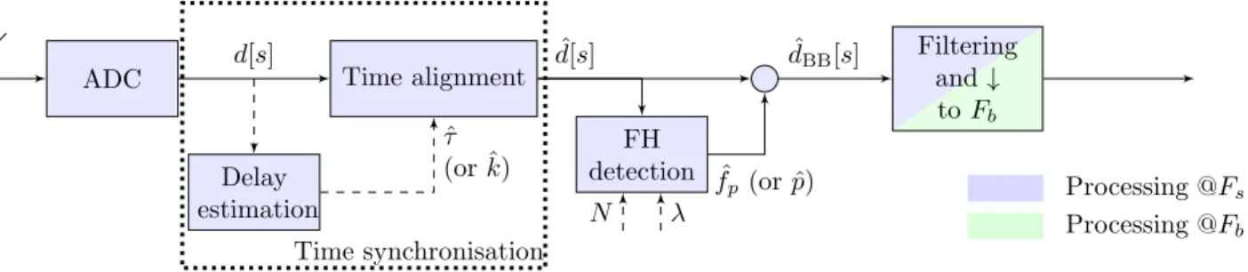
ADC Delay estimation Time alignment d[s] FH detection ˆfp (or ˆp) Filtering and ↓ to Fb ˆ τ (or ˆk) N λ ˆ d[s] dBB[s]ˆ Processing @Fs Processing @Fb Time synchronisation
Fig. 1: Proposed architecture of the interception system.
withfp the associated channel frequency of transmitted sym-bols ofb(t). Assuming that N channels can be used, then
fp= p × Fb= p × Fs
N , p = 0, . . . , N − 1. (2) The same FH indexp is maintained constant for a slot duration Tb and thus is used for several consecutive symbols and λ = TbFs
N is denoted the so-called repetition factor. In the following, the received signal d(t) is delayed by τ and is supposed to only be impaired by an Additive White Gaussian Noise (AWGN) of variance σ2
n and is therefore expressed as d(t) = x(t − τ ) + n(t). (3) It is to note that in our work, we assume that the hop sequence (i.e. fp, ∀p) and the transmission delay τ are unknown. The purpose is thus to propose a system capable to recover these parameters to retrieve the baseband message of bandwidthFb.
The proposed solution is described in Fig. 1. This solu-tion can cope with any FH system and is not restricted to TRANSEC case. It will be for instance directly applied to a Bluetooth case in Section V. This method particularly targets systems with very low slot duration (low value of λ), more difficult to tackle.
The architecture is split into different blocks. The delay estimation block that aims to find the delayτ . This processing has only to be done at the beginning of the operation as the estimated parameter τ is not likely to change.ˆ
The time alignment block aims to shift the incoming buffers to match the FH hop, based on the delay estimation ˆτ . The block provides a synchronised input ˆd[s] sampled at Fs of sizeλN associated to an unknown FH carrier frequency fpto estimate.
The FH detector estimates which channel is used. This de-tector requires two parameters associated to the HF sequence generation: N and λ. In this paper, we will assume that these parameters are known by the receiver, as it can be fixed by a standard (e.g for Bluetooth N = 80 and λ = 625). If these parameters are unknown (for instance TRANSEC case), an additional identification block has to be added and investigation toward blind FH identification methods will be remained for future studies.
III. FHDETECTOR
A. FH detection algorithm
To deal with the large bandwidth, the interception method is supposed to be implemented in a high performance SDR that embeds both hardware and software computational resources. The blue stages of Fig. 1 operate at the higher rate (Fs) and should therefore be implemented in the hardware resource, whereas the green stage operates at lower rate and can be implemented in the software resource. The Analog-to-Digital Converter (ADC) from the SDR device samples the signal at the maximum FH rate (i.e. atFs).
The FH detector estimates which channel is used. The detector is based on the instantaneous periodogram, averaged by the repetition factorλ. This can be efficiently implemented by means of Fast Fourier Transform (FFT) ifN is a power of 2. Considering the input ˆd[s], the associated estimated channel indexp is expressed asˆ ˆ p = arg max p∈[0;N −1] (λ−1 X l=0 N −1 X m=0 ˆ d[lN + m]e−j2πmp N 2) . (4)
Then the chosen index (linked to the central frequency by ˆ
fp = pFˆ s
N ) is used in the de-rotor that shifts the modulated channel into baseband (circle operator in Fig. 1):
ˆ
dBB[s] = ˆd[s]e−j2πs ˆFsfp. (5)
The filtering stage lowers the rate of the detected signal from Fs to Fb. If the correct FH channel has been chosen, and assuming an ideal filtering operation, the resulting signal is TRANSEC messageb(t).
The proposed structure aims to recover the FH signal while initially being sampled at the full bandwidth (at Fs). It requires a perfect time-frequency localisation. To that goal, the frequency estimation is averaged by a factor λ and its accuracy is therefore enhanced. The time synchronisation accuracy required to ensure a proper decoding is evaluated in the next section.
B. Simulation results
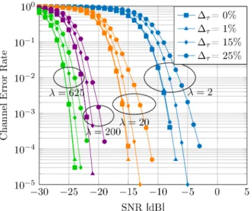
The performance of the detector is evaluated in terms of Channel Error Rate (CER), defined as the probability that the estimated channel index p differs from the effective channelˆ index p. Fig. 2 shows the CER versus the Signal-to-Noise Ratio (SNR) defined from (3) asσ2
Fig. 2: Channel Error Rate vs SNR for various λ and delay errors ∆τ.
of the mixed signal defined in (1). This CER is computed for various values of λ and different synchronisation errors ∆τ. The time synchronisation error is defined as the delay error normalized with the burst duration, i.e.:
∆τ =|τ − ˆτ |
Tb . (6)
The simulation parameters are N = 80, Fs = 80 MHz and Fb = 1 MHz. The value of λ is associated to slot duration from2 µs (i.e very short, λ = 2 in purple) to 200 µs (λ = 200 in blue). We have also depicted the case λ = 625 (in green) which corresponds to the Bluetooth case. It shows that the detector is more resistant to the noise for high values of λ, as the noise is averaged in (4). Fig. 2 shows that the required fine synchronisation is linked to the slot duration. Indeed, in case of synchronisation mismatch, some of the inputs of the periodogram would be associated to the previous or to the next slot. In the meantime, one can say that a synchronisation error lower than 15% of the slot duration leads to a small performance penalty. This metric is fruitful to build a simple yet functional synchronisation stage.
IV. TIME SYNCHRONISATION
A. Proposed approach
The previous section has demonstrated the necessity to propose an efficient synchronisation method, capable to cope with a wide range of burst duration (i.e.λ). The purpose of this section is to describe the synchronisation method. As shown in Fig. 1, this algorithm is placed upstream the FH detector and is only used at the beginning of the interception process as the synchronisation delayτ is assumed to remain constant. It takes the complex baseband samples as input and outputs the estimation delay τ . To achieve a fast synchronisationˆ algorithm (running at Fs), a limited complexity is required
and, thus, methods using maximum likelihood [11], wavelet transform [12] or machine learning [13] can not be used. The proposed algorithm relies on Fourier transform to detect the signal hop with a high time resolution.
The first approach is to use the FFT [14] as used by the FH detector. Its size is equal to the number of channels N (with eventually zero padding to achieve a required power-of-2). The time accuracy is quite low as the resolution is directly linked to the FFT size. The detector will not be able to detect a hop with an accuracy smaller than N samples (in the best case, without noise). This time resolution can be problematic when the burst duration is very short (i.e. small values of λ are common in TRANSEC scenario). In order to increase the time accuracy, the proposed approach relies on a sliding Discrete Fourier Transform (sDFT). It computes a new spectral transform for each incoming sample. To lower the complexity overhead of the sliding approach, a sDFT is used instead of a sliding FFT (sFFT) as it reuses the previous outputs (while a sFFT recalculates the full transform for each sample) in an adaptive manner. Moreover, the adaptive calculation does not require N to be a power-of-2 as with FFT radix based implementation.
From the raw output of the sDFT, additional post-processing is required to extract a delay estimation. The full algorithm is described in the next part. The synchronisation step has a higher complexity than the FH detector. However, the detector has to be used for the whole interception process (in a real time manner) while the delay estimation block has only to be used once, at the start of the interception (and real time is not fully required).
B. Time synchronisation algorithm
Based on the expression of the received signal in (3), the purpose is to findˆτ . As the received signal d[s] is sampled at
Algorithm 1: Delay estimation
// Evaluate the bin index of current channel used for each sample fors = [1 : λN × L] do S ← |sDF T (d[s])|2 V [s] ← arg max(S) end ¯ V [s] = 1 α× Pα−1 l=0 V [s + l]
// Evaluate the shift in the bin index, generate the associated pool and fix detected outliers
M [s] = | ¯V [s] − ¯V [s − 1]|
C0← Find each end of non-zero area in M ; C = Correct outliers (C0);
// Evaluate synchronisation time
C ← sort(C, ascend); ˆ
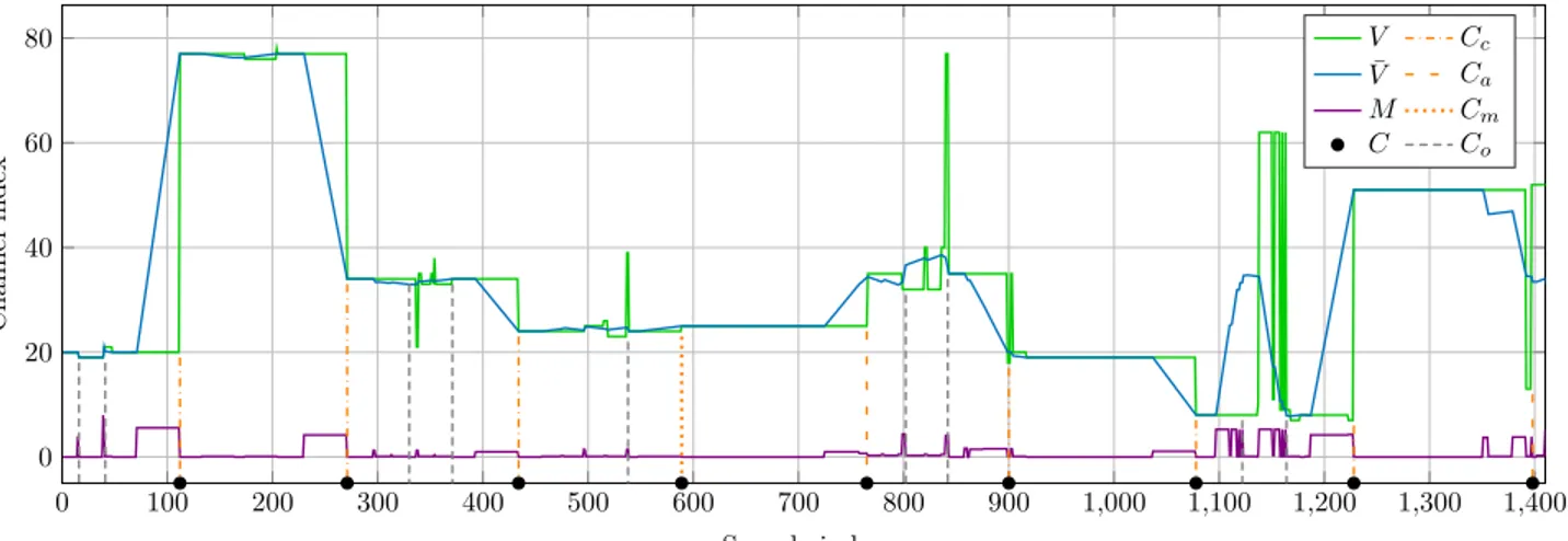
0 100 200 300 400 500 600 700 800 900 1,000 1,100 1,200 1,300 1,400 0 20 40 60 80 Sample index C h a n n el in d ex V Cc ¯ V Ca M Cm C Co
Fig. 3: Chronogram of the various delay estimation steps.
1/Ts (with s the sample index), we want to find the sample delay indexk defined by:
k = ⌊τ × Fs⌋ . (7) The delay estimation step will process L × λN samples of the signal d[s] where L is the number of slots used for the synchronisation. Estimating the synchronisation delayτ (or aˆ synchronisation index ˆk = ⌊ˆτ × Fs⌋) can be done by detecting each hop. Indeed, a hop occurs whens verifies:
s = l × (λN ) + k, ∀l ∈ [0; L − 1], (8) and d[s] is expected to face at most L hops. The proposed algorithm estimates the used channel with a high time accuracy and deduces the synchronisation delay ˆk. This value will then be used by the time alignment block.
The algorithm is sequential and is divided into three main stages described in Algorithm 1. The first stage intends to extract the used channel for each incoming sample. The second stage estimates the hop locations and removes noise artefacts. Finally, the last stage gathers all the hop indexes and estimates the fine time delay estimation ˆk. An illustrative chronogram of the different algorithm variables is depicted on Fig. 3. In this simulation, the parameters are N = 80 and λ = 2 (short burst duration as it corresponds to the worst case scenario of Fig. 2), leading to a hop duration ofλN = 160 samples. The sample delay index is set to k = 110 and L = 9 bursts are used for the delay estimation.
As discussed in Section IV-A, the first step applies the sDFT and associates each sample with the channel with maximum energy in V [s] (i.e. for each sample, the position of the maximum of the sDFT) depicted in green on Fig. 3. As this row estimation can strongly be affected by the additive noise,
¯
V [s], the sliding average of V [s] with a depth α, is computed (blue curve with α = λN
4 ). A hop is defined as a variation in the channel index and can be primarily obtained from the instantaneous derivative M [s] = | ¯V [s] − ¯V [s − 1]| (violet curve). If the channel index remains constant, the derivative is equal to zero. Thus a hop can be defined as the end of
a non-zero area of M [s]. It should be pointed out that we have area (several consecutive terms of M [s] different from zero) instead of peaks as the derivative is computed from ¯V , the sliding average ofV . The obtained hop locations are then gathered in a pool C0. There are however some cases where hops are not detected properly, and some additional processing has to be done.
The next step is thus to correct outliers data to transform the initial pool C0 into the new pool C. Data contained in the pool can be of two types, correctCc or outlier. Moreover, there can be three types of outliers. i)Capresence of too close hops with respect to the expected duration expressed in (8). These hops will then be aggregated to form a single hop in the pool (orange dashed lines). ii)Cmabsence of a hop which is either due to the successive use of two nearby channels drown in noise or to the re-use of the same channel. In this case, the missing end hop is generated in the pool (orange dotted lines). iii)Co presence of a hop out of the hop grid: this can be due to impulsive noise or reception of a third party signal. In both cases these hops will be discarded from the pool (black dashed lines).
Fig. 3 clearly shows that both the sliding average (transition from green to blue curves which removes most unwanted artifacts as for instance around sample 350) and the outlier correction improve the detection. The outliersCa andCohave been successfully detected and extracted and the missing hop Cmhave been generated. At the end, the hop position can be extracted in the poolC = Cc∪ Ca∪ Cm (black circles).
The final step consists in arranging the hop positions inC in chronological (i.e. ascend) order. As the elements inC should follow (8), a linear regression is carried out to obtain the delay estimation ˆk as the Y-intercept. Finally, this value is used by the time alignment block to obtain the signal used in the FH detector in (4) with:
ˆ
0 10 20 30 40 50 60 0
10 20 30
Number of slots used for synchronisation L
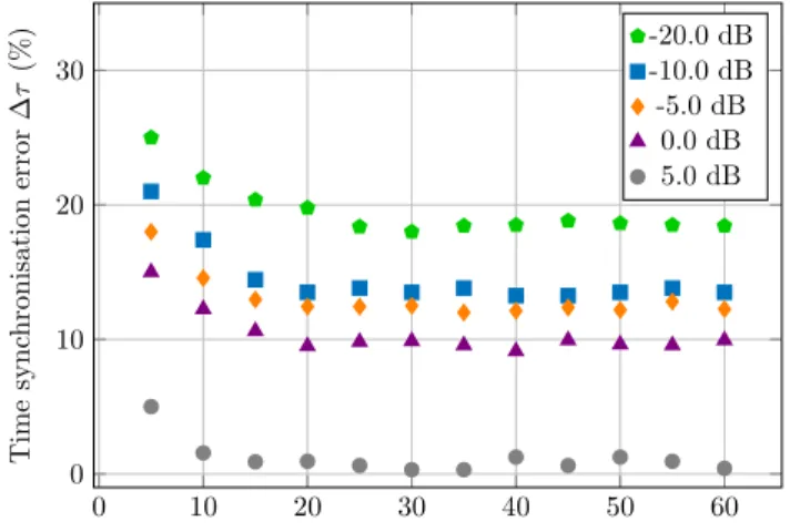
T im e sy n ch ro n is a tio n er ro r ∆ τ (% ) -20.0 dB -10.0 dB -5.0 dB 0.0 dB 5.0 dB
Fig. 4: Timing error of delay detection.
C. Simulation results
The performance of the algorithm is evaluated by simulation on a TRANSEC-like signal with short burst duration. The simulation parameters are the same as for the FH detector: N = 80, Fs= 80 MHz, Fb= 1 MHz and the slot duration is equal toTs= 20µs (λ = 2). As it has been done in Section III-B, the performance is assessed in terms of synchronisation error defined in (6).
Fig. 4 shows the synchronisation performance according to L, the number of slots used to estimate the time delay. Performance are given for different SNR. Results show that synchronization is possible with only 5 hops. Besides, the accuracy is improved until 20 hops where a floor is observed. As the complexity of this processing increases with the number of slots used, we point out that the value of 20 used slots is a good trade-off between synchronization accuracy and computation time. The synchronisation error is at this stage below to the target of 15% defined in Section III-B (see Fig. 2). It should also be noted that these results can easily be extended to higher value of λ with comparable results.
V. BLUETOOTH LISTENING
A. Experimental bench
The proposed method can handle any kind of FH signal with a wide range of burst durations and bandwidths. In this section, our algorithm is evaluated in a real Bluetooth interception scenario. Bluetooth systems are the most commercially avail-able devices that use FH. Targeting Bluetooth eases to validate the two proposed processing blocks (i.e. synchronisation and FH detection) because the parameters needed for our method are known with Bluetooth standard (burst duration, number of channels and carrier frequency).
The interception bench is depicted on Fig. 5. A Bluetooth audio streaming link is set between a laptop and headphones. The interception is performed with an Ettus X310 SDR with an omni-directional antenna, located near the laptop at one meter from the headphones. With this setup, the SDR receives different power levels from the headphones and the laptop. As
Fig. 5: Experimental setup.
this SDR is capable to sample a 100 MHz bandwidth, the full Bluetooth band (80 MHz) is sampled with a 20MHz roll-off at the edge of the useful band. Data from the SDR is then buffered and processed by a laptop using an Intel core I7-8850H. The whole interception system is implemented in Julia language [15] using UHD drivers for Ettus X310 monitoring.
B. Channel index extraction
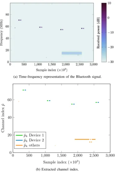
Fig. 6 gives the results from a30 ms recording (correspond-ing to3.106 samples). Fig. 6a shows a time-frequency repre-sentation of the raw data sampled by the SDR while Fig. 6b gives the extracted channel index provided by the proposed channel detection algorithm. The time synchronisation step has been done beforehand this recording. In Fig. 6a, four Bluetooth exchanges can be seen, starting at samples 300, 1050, 1800 and 2550 (×103). The transmission of the different devices can be clearly distinguished. For each exchange, we can firstly see a burst from the laptop with a power of about 0 dBm, followed by a burst from the headphones with a −10 dBm power. The SDR measures a higher power for the laptop than for the headphones, the laptop being closer to the SDR than the headphones. In addition to these two devices, other traces are visible in the spectrum with a low power (below−20 dBm): a long burst emission (probably Bluetooth 3.0 High Speed) is visible from samples 1860 to 2550 (×103) and an exchange between two other Bluetooth devices at sample 2360 (×103). The whole interception process is then applied on the received signal. In addition, a straightforward separation of the signals from each device is made based on their received power and burst duration.
Results are given in Fig. 6b where laptop traffic is shown in green, headphone traffic in blue and the others are shown in orange. The current channel is detected properly, in accordance to Fig. 6a. Only one channel is detected at once, as can be seen between samples 1860 to 2550 (×103), which means we are able to discriminate useful information from noise and even to distinguish the devices from each other. From the channel indexp, a real time narrowband baseband signal canˆ be obtained from (5). As the processed bandwidth is drastically reduced, this clearly paves the way for fast useful information extraction.
(a) Time-frequency representation of the Bluetooth signal. 0 500 1,000 1,500 2,000 2,500 3,000 0 20 40 60 Sample index (×103) C h a n n el in d ex ˆp ˆ pk Device 1 ˆ pk Device 2 ˆ pk others
(b) Extracted channel index.
Fig. 6: Bluetooth interception results.
VI. CONCLUSIONS& FUTUREWORKS
This paper focused on the recovering of the hop sequence into frequency hopping signals. In this paper, we focused on TRANSEC systems, which are based on frequency hopping with a high number of hops per second over a wide bandwidth. A new frequency hopping interception scheme has been pro-posed with low complexity and capable to estimate the used channel even with a very low slot duration. We have demon-strated that the required time synchronisation can be relaxed to 15% of the slot duration to correctly estimate the used channel and this synchronisation precision can be achieved after only 20 hops. Finally, the method has been validated by listening to a commercial Bluetooth devices and blindly detecting its frequency hops. Next steps will be to improve the algorithmic part by estimating both the number of channel and the burst duration, and to enhance the implementation part with FPGA acceleration.
ACKNOWLEDGEMENT
This study is supported by the Pˆole d’Excellence Cyber.
REFERENCES
[1] P. Fraga-Lamas, L. Castedo-Ribas, A. Morales-M´endez, and J. M. Camas-Albar, “Evolving military broadband wireless communication systems: Wimax, lte and wlan,” in Interna-tional Conference on Military Communications and Informa-tion Systems (ICMCIS), 2016, pp. 1–8.
[2] F. L. Coman, K. M. Malarski, M. N. Petersen, and S. Ruepp, “Security issues in internet of things: Vulnerability analysis of lorawan, sigfox and nb-iot,” in Global IoT Summit (GIoTS), 2019, pp. 1–6.
[3] Y.-S. Shiu, S. Y. Chang, H.-C. Wu, S. C.-H. Huang, and H.-H. Chen, “Physical layer security in wireless networks: A tutorial,” IEEE Wireless Communications, vol. 18, no. 2, 2011.
[4] A. A. Abidi, “The path to the software-defined radio receiver,” IEEE Journal of Solid-State Circuits, vol. 42, no. 5, pp. 954– 966, 2007.
[5] G. Camurati, S. Poeplau, M. Muench, T.Hayes, and A. Francillon, “Screaming Channels: When Electromagnetic Side Channels Meet Radio Transceivers,” in Proc. ACM conference on Computer and communications security (CCS), Oct. 2018. [6] L.-L. Yang and L. Hanzo, “Software-Defined-Radio-assisted adaptive broadband frequency hopping multicarrier DS-CDMA,” IEEE Communications Magazine, vol. 40, no. 3, pp. 174–183, 2002.
[7] J. J. Lehtomaki, “Maximum based detection of slow frequency hopping signals,” IEEE Communications Letters, vol. 7, no. 5, pp. 201–203, 2003.
[8] A. Valyrakis, E. E. Tsakonas, N. D. Sidiropoulos, and A. Swami, “Stochastic modeling and particle filtering algorithms for tracking a frequency-hopped signal,” IEEE Transactions on Signal Processing, vol. 57, no. 8, pp. 3108–3118, 2009. [9] J. S. Aziz, A. A. AL-Shalchi, A. K. Al-Kateeb, and F. N.
Pavlidou, “Parameter estimation of frequency-hopping (fh-ss) signals using modified autocorrelation techniques,” in Inter-national Conference on Communication Technology, 2006, pp. 1–4.
[10] O. Berder, C. Bouder, and G. Burel, “Identification of Fre-quency Hopping Communications,” in Problems in Modern Applied Mathematics. Published by: WSES, 2000, pp. 259– 264.
[11] C. C. Ko, W. Zhi, and F. Chin, “ML-based frequency esti-mation and synchronization of frequency hopping signals,” IEEE Transactions on Signal Processing, vol. 53, no. 2, pp. 403–410, 2005.
[12] M. Sirotiya and A. Banerjee, “Detection and estimation of frequency hopping signals using wavelet transform,” in UK-India-IDRC International Workshop on Cognitive Wireless Systems (UKIWCWS), 2010, pp. 1–5.
[13] Y. Zhang, W. Yang, and Y. Cheng, “Sparsity analysis of fh-bpsk signals via k-svd dictionary learning,” in IEEE Inter-national Conference on Computer Communication and the Internet (ICCCI), 2016, pp. 310–315.
[14] H. Sorensen and C. Burrus, “Efficient computation of the short-time fast fourier transform,” in International Conference on Acoustics, Speech, and Signal Processing, 1988, 1894– 1897 vol.3.
[15] J. Bezanson, A. Edelman, S. Karpinski, and V. B. Shah, “Julia: A fresh approach to numerical computing,” SIAM review, vol. 59, no. 1, pp. 65–98, 2017.