A DIGITAL RADIO MODEM FOR THE
MOBILE ROBOT PROJECT
by
Carl Martin etrzak, Jr.
Submitted to the department of
Electrical Engineering and Computer Science in Partial Fulfillment of the
Requirements of the Degree of Bachelor of Science
in Electrical Engineering at the
MASSACHUSETTS INSTITUTE OF TECHNOLOGY
June 1985
0
Carl Martin Pietrzak, Jr. 1985The author hereby grants to M.I.T. permission to reproduce and to distribute copies of this thesis document in whole or in part.
Signature Redacted
Signature of Author IIIs,
Department of Electrical Engineering and Compuo;K Science
ay 2 9, 1985
Signature Redacted
Professor Rodney A. Brooks
Signature Redacted
Thesis supervisor Accepted byProfessor Leonard A. Gould
ARCHIVES Department Committee Chairman
MASSAC I 10TUn
DEC
111985
A DIGITAL RADIO MODEM FOR THE
MOBILE ROBOT PROJECT by
Carl Martin Pietrzak, Jr.
Submitted to the Department of
Electrical Engineering and Computer Science on May 29, 1985 in partial fulfillment of the requirements for the Degree of Bachelor of Science in
Electrical Engineering
ABSTRACT
Using four Motorola MX340 hand-held radios, a 12 Kilobit/ sec. radio modem was constructed. It is intended to be
flexible and rugged enough to be used in any project at the AI Lab requiring such a device. A surrounding system
including antennas, duplexers, and interface circuits was designed to utilize this modem in the Mobile Robot Project. The modem will provide a better environment for the
development of the robot system by ensuring fast and reliable communications with a LISP Machine. The LISP Machine was appropriately modified to interface with the modem.
Thesis Supervisor: Dr. Rodney A. Brooks
ACKNOWLEDGEMENTS
I would like to thank Prof. Brooks for giving me the
opportunity to complete the work I began on this modem through UROP by advising this thesis. He shows a degree of support and enthusiasm toward me and the other students working on the Mobile Robot Project that is uncommon in the department of EECS; it was a pleasure working for him.
I would like to thank my student coworkers for their assistance with this thesis. Ed Kim provided an excellent sounding board for my RF designs, John-Paul Mattia and Sathya Narayanan helped me with the LISP Machine modifications and programming, and Anita Flynn helped me find equipment and other facilities around the AI Lab.
I am grateful to Bill Chichairo of Lincoln Labs for his analysis of the radios and the duplexers, and to Craig Rogers for running the scanner test.
I am especially grateful to Motorola, Incorporated for the donation of the radios, without which nothing could have been done. I appreciate the assistance I was given by Sue Thomson, John Kuzma, and Doug Mach to achieve the donation. I
am also grateful to Eric Ziolko, Al Wilson, and Paul Bocci for their help as technical consultants. Each provided valuable information towards the modification of the radios and their implementation in the modem system.
technical drawings, machining of the copper boxes, and for all those things that cannot be defined on paper and for those which would be to numerous to list.
TABLE OF CONTENTS
I. INTRODUCTION 9
II. THE RADIOS 11
A. Why Use MX300's? 11
B. Further Literature 13
III.FROM WALKIE-TALKIES TO MODEM 15
A. Modifications 15
B. System Structure 16
C. Other Issues 17
IV. INTERFACING THE MODEM TO ROBOT SYSTEM HARDWARE 18
A. Line Levels 18
B. Synchronization 18
C. Constraints on the Data Sent through the Modem 19
D. CADR Modification 22 E. Robot Interface 22 V. RF ISSUES 24 A. Isolation 24 B. Antennas 26 C. Interference 27
VI. SOFTWARE ISSUES 28
A. Timing Constraints 28
B. Full Duplex vs. Half Duplex 29
C. Splatter Filters and Linear Coding of Data 30 D. Error Correction Codes 30
VII. CONCLUDING REMARKS 32
APPENDIX A: MX340 SPECIFICATIONS 33
APPENDIX B: LISP PROGRAMS 35
APPENDIX C: FULL DUPLEX PSEUDO-CODE 38
LIST OF FIGURES
Number and Title page
1. DVP Transmitter Block Diagram 41
2. DVP Receiver Block Diagram 41
3. Controls on top of MX340's 42
4. Connection Pad Signal Locations 44
5. Data Links 45
6. Splatter Filter Effects 46
7. CADR I/O Board Modifications 47
8. Handshake Timing Test 48
9. Duplex Operating Curves 49
10. Isolation vs. Antenna Separation 50
11. RF Isolation System 51
12. Explosion Diagram of Copper Box 52
13. Robot Antenna Assembly 54
14. Spectrum Analysis of MX340's (Wide View) 55 15. Spectrum Analysis of MX340's (Narrow View) 56
LIST OF TABLES
Number and Title page
1. MX340 Channel Frequencies 43
2. Parts List for Fig.12 53
INTRODUCTION
The Mobile Robot Project under the direction of Professor Rodney Brooks differs from other robot projects in several ways, one of which is its goal of developing a robot which operates in the real world. To accomplish this goal, the robot must operate using robust, real-time software and control
systems. Addressing the software and computer architecture issues is the primary concern of this project. Prof. Brooks proposes solutions to several of these problems in Working Paper 265, but this paper mainly builds a framework in which the evolution of software and system structure will occur. To provide a better environment for system development Prof.
Brooks decided to simulate computers on-board the Robot with a dedicated CADR and connect the CADR to the robot via some
communications link. The construction of such a link is the topic of this thesis.
I first undertook this project through a UROP titled Robotics and Radio. In the interest of continuity of
information, the results of this UROP are described in addition to the work which was conducted afterwards specifically for this thesis.
To meet the goals of the robot project I decided to construct a high-speed radio modem. A radio link allows the robot to communicate with its host computer from any location
within the radios' range. This digital radio modem was
constructed with four goals in mind: 1) To provide reliable communication 2) at the highest possible speed 3) using
hardware that is simple to use by people not very familiar with radios 4) and easy to adapt for use in other systems at the AI Lab.
THE RADIOS
Why Use MX300's?
No commercially available radio modems exist that exceed 2400BPS data rates for a reasonable price. However, while working for Motorola, Inc. through the VI-A program, I became familiar with the MX300 series DVP (Digital Voice Protection) hand held radios. MX300 series radios are highly advanced FM
"Handie-Talkies which can operate in either a standard (clear) or private (coded) mode. Clear mode operation employs standard narrow band FM transmitting and receiving techniques. Of
greater interest, however, is the digital circuitry used in DVP coded mode.
Before modification, the DVP section of the radios'
transmitters could be described by the block diagram in Fig.1. The CVSD (continuously variable slope delta) digitization
changes an analog voice wave into a string of l's and O's. The voice wave is sampled at 12 Kilobits per second. Digitizing the voice wave permits easy processing of the information.
Specifically, these radios employ a public key encryption algorithm to create a high security link to other radios.
Encryption is performed in a separate hybrid, whose pinouts are easily accessible. The output bit stream of the encryption
hybrid is fed to the modulator. Modulated output is filtered to remove the tremendous band splattering caused by the
impulse-like transitions in the digital signal, and then amplified and radiated.
The receiver section uses the same digital components as the transmitters though the RF circuitry is naturally
particular to receivers, as shown in Fig.2.
Because of thir digital circuitry and speed of data transmission, these radios are especially well suited to communicate with computers. Recognizing this fact, Ed Kim a
fellow VI-A and UROP student, and I negotiated with Motorola for the donation of six of these radios. Motorola obliged and we received six, 2 watt, UHF, MX340 hand-held radios and
various accessories including ni-cad batteries and antennas. Specifications of the radios are provided in Appendix A.
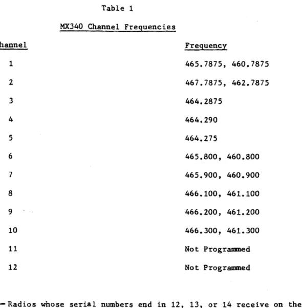
The radios have a minimum number of controls to allow ease of operations. The location and setting of these controls are shown in Fig.3. The Volume/On/Off and Channel Select knobs are self explanatory. A frequency listing for the channels is
provided in Table 1. Note that channels 3,4,5,11, and 12 are currently unusable in the modem system. These channel
frequencies as well as the others, can be reprogrammed by a Motorola Service Center if desired. The red Transmit Light is
illuminated when the radio is transmitting. The antenna jack normally connects the antenna to the radio, but is bypassed in the modem system, as will be described later. The squelch is a variable threshold that will enable audio output only if a
sufficiently strong signal is received. This feature is used by radio operators to avoid constantly listening to background
static while listening for messages directed to them. The squelch is functional only whin the receiver is operated in clear mode. In coded mode, the receiver relies on a squelch that is fixed internally. Since the AI Lab contains an
especially RF noisy environment, and the received signals from our modem will be strong, the receivers will be operated in clear mode and the squelch threshold will be set at a high value. The headphone jack allows the attachment of external headphones. This feature is not relevant to the modem. The last control on top of the radio is the mode switch. The markings are somewhat obscure and should be explained. The position marked "0" places the radio in "clear" mode. In this mode the
radios operate the same as any commercial FM walkie-talkie, using standard FM voice transmission and reception. The
position marked "4 " enables the PL (Private Line) circuitry. The radio still operates in clear mode but also transmits a
sub-audio tone with each voice transmission. In this mode the receiver will not unsquelch (enable audio output) unless this sub-audio tone is received. The audio output is also subject to the squelch control. The position marked "0 " enables the
radio's DVP and related digital circuitry. In this "coded mode" the variable squelch control is disabled and only a
sufficiently strong digital signal will unsquelch the radio.
Further Literature
This chapter provides a brief overview of the MX300 series radios and their operation. More detailed information,
including schematics and alignment procedures, can be found in Motorola's "MX300-S Series Handie-Talkie" Portable Radios with
Digital Voice Protection service manual, and MX300 Series
FROM WALKIE-TALKIES TO MODEM
Modifications
Figs.1 and 2 suggest a simple way of changing the radios from walkie-talkies to parts of a modem: cut the signal path from encryption to modulation on the transmitter and from limiting to decryption on the receiver. This modification
turned out to be very easy. In all Motorola radios, most useful signal lines are accessible via "I points" and other well
marked solder connections. All of these lines in the MX340's are available on the connection pad of Modu-Flex Circuit
NLE9340A, which resembles the back side of a 38 pin dip, though it is not. Modification amounted to simply soldering wires to these connections and connecting them to the computer's
hardware through some simple interface circuits.
The flex circuit connection pad is located at the bottom of the radio on the circuit board side. Connection No.1 is at the top right corner of the pad and No.38 is below it. Fig.4 shows the location of the modification connection on the pad.
CSI is the chip select for the encryption/decryption hybrid. Grounding CSI with a jumper effectively makes the cut described above. Normally, the encryption hybrid drives CTO with its output bit stream and is driven by CTI, the bit stream recovered by the radio's receive circuitry. Deselecting the hybrid allows computer streams to be inserted and extracted via
lines soldered to CTO and CTI, respectively. CTO and CTI are TTL compatable, though communication with them must occur synchronously using CLK as the synchronizing clock.
137 can be used to remotely toggle between receive and transmit. In the mobile robot system, one radio will be dedicated to transmitting and one to receiving at each location. This line can therefore be used to save power by turning the transmitter on and off. It can also be used as an
"Acknowledge" or "Request to Send" hand shake line. Turning the transmitter on involves grounding 137 (the PTT line, as it
shall be called). Less than 0.5 mA must be drained. Setting I37/PT to high impedance will disable the transmitter. 136 is another useful line, unsquelch or UNSQ. This line goes low when a sufficiently strong signal is detected opening the squelch. UNSQ provides a "someone is talking to you" signal and when used together with PTT, completes a handshake.
System Structure
The system developed using the appropriately modified MX340 redios is a 12 Kilobit per second, full-duplex, radio modem. Each site, either the robot or the CADR, maintains two radios, one dedicated to transmitting and one to receiving. Two radio links are set up, one "HI" frequency and one "LO"
frequency. Fig.5 illustrates the arrangement. The robot's transmitter transmits on a frequency 5MHz below that on which the CADR's radio transmits. The robot's receiver listens on the CADR's transmit frequency and the CADR's receiver listens on
the robot's transmit frequency. These two radio links provide full duplex (simulteneous transmit and receive) operation.
Other Issues
The modem has been developed at the system level. The rest of this thesis concerns itself with specifying the modem at a
lower level. Connection to computer hardware, software, and RF issues will be discussed.
INTERFACING THE MODEM TO THE ROBOT SYSTEM HARDWARE
Line Levels
The modem, which consists of a transmitter and a receiver, provides six signal lines which must be connected to external computer hardware. The lines and their voltage levels are listed below:
RXDAT/TXDAT Ov low, 5v high
RXC/TXC Ov low, 8v high
PTT drain < 0.5mA to assert
UNSQ Ov low, 5v high
All signals except the clocks TXC and RXC are TTL
compatible. The clock lines must be buffered with a CMOS 14049 inverting buffer. An inverting buffer is necessary as opposed to a non-inverting one, since the Robot and CADR USART chips require TXCLK and RXCLK.
Synchronization
To transfer data to and from the radios, external hardware must be synchronized to the radios' clocks. Each radio contains a 12 KHz clock for its internal digital circuitry and the
computer must synchronize to each separately. Both the CADR and Robot employ the 2651 UART for their serial I/O. This chip has full duplex capability through the use of separate transmitter and receiver sections and their respective external clock
radios are well within the chip's external clock specifications.
Constraints on the Data Sent through the Modem
The radios are, in a broad sense, transparent to the data sent through them. Protocol such as stop and start bits and parity are unnecessary as far as the radios are concerned; they will send whatever is given to them. However, the modem is an AC-coupled data link. The transmitter splatter filter removes DC components to reduce output bandwidth. As a result, setting the TXD line high or low for many clock cycles, as is the usual idle condition on a hard wire link, is meaningless. The
transmitter filter will cause some arbitrary default condition to be sent and as a result of its capacitors being fully
charged or discharged, will react sluggishly to a sudden
transmission of data. A character sent after setting TXD low or high for, say, 1000 clock cycles will not go through the filter and thus not be recovered at the receiver. To prevent this condition, the idle pattern on the TXD line should be a square wave. The line may be set low or high for a short time on the order of 10 clock cycles, signaling that data is about to be transmitted, but some fairly high frequency square wave should be placed on TXD between packets of information. 6KHz is of course the highest frequency square wave (and is the letter
"U" in Ascii, incidently) that can be sent but the wave could just as well be 1 KHz. Indeed, different frequency square waves may be used to inform a distant station of local status
conditions. Such possibilities will be discussed later in this paper.
Even using square waves between data packets, may not cure errors caused by the splatter filter. The time constants in this filter were optimized at Motorola for use with encrypted data. This means that the data must have a fairly even
distribution of l's and O's. Actual 1 and 0 evenness versus error rate tests were not performed, but I discussed the issue with Motorola engineers and ran a rough test.
The test set-up and results are shown in Fig.6. the
transmitter's RF was fed directly into the receivers through an attenuator to eliminate environmental interference. The Lisp machine was loaded with the programs SerialMod and TestSerial whose listing are provided in Appendix B. Evaluating:
(forever-sent-stream mobot serial (stream 'UUUUU)) asserted a 6 KHz square wave, on TXDAT and an oscilloscope
proved that the wave appeared on RXDAT with no errors. Changing the second argument to (stream 'TTTTT) creates a non-random continuous wave to be sent. Ascii for T is 01010100. The scope revealed some errors on RXDAT, about one occurrence every
second. It is expected that these are burst rather than single errors. Both the noticeable length of time of error on the scope and an understanding of of the cause of the errors lead me to this conclusion. The scope was triggered by TXDAT so trigger loss did not cause the delay. Still worse results were obtained when sending a stream of A's whose Ascii code is
tenth of a second or so after the A's were asserted at TXDAT. The recovered wave then degraded as shown in Fig.6.
The immediate solution which comes to mind is to use the encryption already provided within the radios and make "the cut" between the CVSD and encryption in Figs.1 and 2. This solution is undesirable, however, because of the nature of the code. The code uses several maximal-length number generators to produce a non-linear, public key code. This code is self
synchronizing and needs no preambles. While such a code provides a high degree of security, synchronization is not
instantaneous. The resulting trade-off is error multiplication. One error in the text produces 32 errors at the destination. The Robot operates in a noisy environment and requires a more reliable data link. Using this code is out of the question.
However, sending an even number of l's and O's on the average is not too difficult. Data, by its very nature, should be fairly even within 1000 bit blocks. It is worth while to attempt a system run without taking any measures to even out signals sent through the modem. If further encoding is
necessary, a simple linear code should provide an even enough distribution of l's and O's. One example:
append 00 if number l's > number O's 01 if number l's = number O's 11 if number l's < number O's
Such a code maps eight bits into ten. If encoding is performed in hardware, 9600 baud transfers can be maintained.
One simple hardware implementation uses two EPROMs. The Ascii character would be presented at the EPROM's address lines. The content of that address would be the 10 bit code which would be fed to the UART.
A surer and simpler fix would employ Manchester encoding. Manchester encoding maps a 1 into a 10, and a 0 into a 01.
Speed of data transfer would drop by a factor of two, but reliable transfer of data would be assured.
CADR Modification
Interfacing the radios to the CADR is a relatively
painless procedure. A direct connect to the CADR's serial port is not possible because of the +12v to -12v RS-232 output
level. The radios must directly access the 2651 USART on the I/O board. The wire connections and their locations on the I/O board are listed in Fig.7. Also listed are the color codes for the wires I have installed on CADR-24. These wires are not intended to be permanent connections, rather temporary test patches. I did not connect PTT to the USART since testing
required me to switch it manually. However, TTL DTR OUT may be a suitable connection. To activate this electrical protocol,
the USART must be initialized as shown in the program
SerialMod.Lisp in Appendix B. A power source is also necessary, of course.
Robot Interface
that for the CADR. However, power is more of an issue on the Robot than at the CADR. The Robot supplies only a finite amount of power from its 8v batteries. The PTT line on the radios was originally installed with this issue in mind. While the
receivers draw very little current (see MX340 specifications in Appendix A), the transmitters each draw an amp and a half.
Robot control of the PTT can help save power by switching the transmitter on and off, instead of operating it at full duty cycle. The radios are nevertheless thermally capable of
RF ISSUES
Isolation
As shown in Fig.5, the modem maintains two radio links 5 MHz apart in frequency. To accomplish this each site contains a transmitter and a receiver operating simultaneously. Even
though 5 MHz may seem like enough separation in frequency for simultaneous operation, it is not. The lower graph in Fig.9 reveals that 43 dB of isolation is required between the transmitter and receiver to prevent the former from lowering the sensitivity of the latter. 46 dB of transmitter noise attenuation is also required.
One way to isolate a receiver and transmitter is to physically separate the radios and their antennas. Required distance of separation can be found from the graphs in Fig.10. The required 50 feet of horizontal separation or 7 feet of vertical separation are both impractical for the Robot's radios.
Since isolation is essential for reliable communication of data and given that a significant amount is needed, I decided not to compromise the system construction regarding this issue. Figs.11 and 12 illustrate measures taken to isolate the radios. Table 2 provides a parts listing for the explosion diagram in Fig.12. Each radio is encased in 40/1000 inch copper boxes. The boxes were formed from a single piece of copper obtained from
the Research Laboratory of Electronics and machined at the
Bld.36 RLE shop. The corners of the box were solder-welded shut with a propane torch obtained from the Tokamak facility also in Bld.36. A torch is necessary not because copper is difficult to
solder, but because the heat conductivity of a solid piece of copper is too great to use an iron.
Copper was chosen over aluminum because of its
solderability, workability and excellent heat dissipation characteristics. Double sided PC board would have been easier
to solder and work with than solid copper, but is not as
mechanically strong.
To prevent RF from traveling on the signal wires, 100pf feed-through capacitors were installed in the box and two
ferrite beads were placed near the capacitor end of the signal wires inside the box. The installation of the capacitors
required drilling holes, tinning the holes and the capacitors with solder, then placing the capacitors in the holes and heating the surrounding copper with a torch. After
installation, the capacitors were tested using the 38-500 lab's capacitance bridge to make sure the torch did not damage them. RF exits the box via a BNC connector which is not soldered to the box, but is connected via two star washers. Double-shielded
504--coax carries the RF to a duplexer. The duplexer consists of four resonant cavities which are tuned to provide a high degree of isolation between the inputs. The duplexers were tested by Bill Chiarchiaro of Lincoln Labs and met
noise suppression and 50 dB of receiver isolation with less than 2 dB of insertion loss. Output RF from the duplexer is fed to the antenna via another length of coax.
The only possible source of RF leakage in this system is from the copper box tops. No measures have been taken to
electromagnetically seal the crack between the box and the cover plate. However, the copper is flexible, and the six sheetmetal screws appear to leave only a few small cracks. I believe 460 MHz is a low enough frequency not to worry about these cracks. If a higher degree of shielding is desired, copper tape should be used to seal the box.
Antennas
The antenna system which I have specified for the robot project is illustrated in Fig.13. This system has not been constructed, but it meets the requirements of both the radio modem and the television transmitter on the robot. An analogous antenna should be constructed at the CADR.
The modem radios have a longer range than the television, and their antenna occupies the less ideal lower position on the mast. It should , however, be clear of all other equipment on
top of the robot. It consists of two sections of brass welding rod which have already been cut. These rods form the two halves of a vertically oriented half-wave dipole antenna. This antenna has superior range and performance with respect to Motorola's
supplied vertical antennas.
directly to a PL259 coax connector. The mounting of the rods deserves more thought, though. The modem and television
antennas must be mounted colinearly to provide isolation. They operate 25 MHz apart, but the more isolation, the better. The antennas are omnidirectional on the plane perpendicular to
them, but their radiation pattern has a null directly above and below them (on the line connecting the two antennas). This fact should be kept in mind if the Robot is operated on a different floor from the CADR. Still, these antennas supplied with two watts of power from the radios should provide satisfactory coverage throughout NE43.
Interference
The MX340 radios emit a very clean signal, even during digital transmissions. A spectrum analysis of the radios was performed at Lincoln Labs and the results are shown from two perspectives in Figs.14 and 15. There is no threat of failing to meet FCC standards. In addition, unwanted interaction
SOFTWARE ISSUES
Timing Constraints
The lack of signal lines and "data transfer ready"
information available to the computer creates a need to install fixed timing constraints in the computers' software. Two times are especially necessary to know:
1. How soon after UNSQ is RXDAT valid?
2. How quickly can a handshake occur?
The test arrangement pictured in Fig.8 was constructed to
measure these times. The analyzer was triggered using the PTT side switch on the transmitter. About 1 ms of contact bounce was detected,--not bad enough to interfere with results. Tests were performed in the evening to avoid on-channel interference. As expected, reaction times were variable. The amount of time
between the assertion of PTT and UNSQ was measured anywhere from 17 ms to 21 ms for the "LO" radios (group 1 in Fig.8). Over 100 tests were performed to allow for radio heating
effects and to set a safe upper bound. Another 100 tests were performed using the "HI" link (group 2 in Fig.8). I found 30 ms
to be a safe reaction time between any transmitter-receiver pair.
These tests were performed with the radios in the same room. Could strength of signal be a factor? A second set of tests were performed, this time with two radios on the 7th floor remotely controlled by two 9th floor radios. This
arrangement is shown in Fig.9. "Ideal" 60 ms transfers did
occur, but not reliably. Several "false starts" occurred in the 60-90 ms time segment; UNSQ would disassert several times
before settling to "assert". No set of false starts endured for a period longer than 20 ms.
Squelch drop timing, the time between the disasserting of
P T and UNSQ, was similarly measured. 140 ms is a safe upper bound on this event. The results reiterated:
1. Time from PTT assert to UNSQ assert across a four radio link where UNSQ at the remote site causes an immediate PTT response = 100 ms.
2. Time for a similar disassertion of PTT and UNSQ =140 ms. 3. Time computer must wait after the first UNSQ is received to be assured a valid UNSQ = 20 ms.
Full Duplex vs.Half Duplex
Initially, the modem will be operated at half duplex (only one site transmits at any given time). Full duplex is more
flexible, however, allowing either the CADR or Robot the
ability to send the other data immediately. While the link does not maintain the required four signal lines for full duplex, DTR, RTS, CTS, DCD, status information can be passed across the
link itself in various ways. Appendix C contains the
pseudo-code for implementing full duplex operation by using different frequency square waves as radio status signals. At the very least, this code demonstrates the ramifications of the time constraints discussed in the previous section.
Splatter Filters and Linear Coding of Data
As already mentioned, some sort of coding scheme may be required to even out the number of l's and O's. This coding need not be performed in hardware and may be more easily done
in software.
Error Correction Codes
This modem operates using an inherently noisy data channel, a radio link. Sources of noise include:
-The surrounding computers
-Splatter filter and receiver front end
-On-channel interference from the surrounding metroplex -Multipathing
The last source deserves explanation. Multipath errors occur when two paths of wave propagation appear. Both paths provide
the same quality of signal transmission, but one, because it is a longer path, delivers a signal that is phase delayed with
respect to the other. These signals interfere and cause errors. At 460 MHz, multipathing is a serious problem. Even people
moving in the vicinity of the radios can act as waveguides, causing multipathing. This problem is further exacerbated by
the motion of the Robot's radios since this motion constantly creates multipaths.
These errors can be dealt with. Multipath and splatter filter effects will tend to cause burst errors; 20-50 bits will be knocked out. These figures were given to me by Motorola
engineers who have studied the problem. The solution is to send "interleaved" data. The procedure is as follows: if 30 bytes of data need to be sent, send the first bit of each of the 30
bytes, then all of the second bits, and so on. If each byte is error encoded with a 2-error code, a 50 bit burst error would cause less than two errors per byte. The error correcting code would absorb these errors and reliable communication would be maintained. Hamming codes are well known error correction codes which can be used on the individual bytes.
The error correction code will also help eliminate sources of random and periodic errors, such as computers and radio
stations causing on-channel interference.
On-channel interference was measured in a one and one half day scanner test. A Bearcat scanner located in Senior house was
set to scan the radios' frequencies and record the number of times its squelch was broken by each channel. The results are listed in Table 3. A significant amount of on-channel
interference exists on all of the radios' duplex channels. (The simplex channels obviously cannot be used in the modem system.) Channel 2 appears to be the least populated and the radios are all set to this channel. However, installation of new
CONCLUDING REMARKS
Though the modem system is still incomplete, the testing which has been performed to date is very encouraging and no unexpected problems have arisen. The actual modem hardware has been completely built and tested, though a lack of antennas and a test set-up representative of Robot to CADR operations
prevent me from saying definitively "it works!" The antenna assembly while not yet constructed, has been designed and most parts obtained. The duplexers must be tuned to the correct frequency. They are currently unusable since they are tuned to amateur radio frequencies. This operation can be performed at Lincoln Labs in an afternoon.
The only information which I have not yet obtained concerns error rates over the link in the Robot's operating environment. I suggest that error counting and other diagnostic programs be run of the CADR to obtain this information. Error rates may be seriously high, but correctly implemented error correcting codes should remedy even the worst of conditions.
Once this testing and construction has been completed, I am confident that the AI Lab will own a very reliable, high performance radio modem.
APPENDIX A
The next page contains a condensed version of the MX340 specifications as listed in Motorola's "MX300-S Series
Handie-Talkie Portable Radios with Digital Voice Protection" service manual. All specifications not relevant to the AI Lab
MX 340 SPECIFICATIONS General Frequency Size Weight Transmitter RF Power Output Frequency Stability Modulation ( 5KHz for 100% modulation at 10 FM Noise Spurios Harmonies Current Drain PL Tone Receiver Frequency Stability Modulation Acceptance Spurious & Image Rejection Current Drain Sensitivity (20dBQ) (12dBSINAD) Selectivity(Adjacent Channel) Intermodulation DVP Digital Circuitry Bit Rate Clock ' 460 MHz Band (UHF) 72mm x 36um x 126mm 17 oz. 2 watts 0.0005% (-30 to +6'C) 16F3 KHz) -45 dB -60/-60dB 1263 mA 2A 0.0005% (-300 to +66C) 7.5 KHz 80 dB 213 mA unsquelched 67 mA squelched 0.5 pV 0.35 p/V -70 dB -70 dB 12 Kilo Bits/Sec 12 KHz
APPENDIX B
The next two pages list the LISP programming used to test the modem. The first page is an excerpt of <ads.cadr>serial.lisp demonstrating the 2651 UART formatting for a CADR. The second page lists the file <ads.cadr>serialmod.lisp which was used to send data through the modem. Only FOREVER-SEND-STRING was used for modem testing. FOREVER-SEND-CHAR did not function properly (reason unknown) and the error counter was never tried. A test similar to the shown error counter should be used for further testing of the modem.
Just load <ads.cadr>serial.qfasl ... actually contains mainly the following.
; Only thing which needs to be changed to run off the external clock. Mode is initialized to
1 stop bit
No Parity
8Bits/Character Async 1X mode
; I think that only the last is needed the rest don't really matter.
;;; Housekeeping methods
(DEFMETHOD (SERIAL-STREAM-MIXIN :INIT) (INIT-PLIST)
(SERIAL-CHECK-EXISTENCE) ;Barf if mach
(LET ((REQUEST-TO-SEND T) ;Parse option
(DATA-TERMINAL-READY T)
(SYNCHRONOUS-MODE NIL))
(LOOP FOR (KWD VAL) ON (CDR INIT-PLIST) BY 'CDDR DO
(SELECTQ KWD
(:REQUEST-TO-SEND (SETQ REQUEST-TO-SEND VAL))
(:DATA-TERMINAL-READY (SETQ DATA-TERMINAL-READY VAL))
(:SYNCHRONOUS-MODE (SETQ SYNCHRONOUS-MODE VAL))))
(%UNIBUS-WRITE 764166 20) ;Reset
(SERIAL-WRITE-COMMAND UART-COMMAND) ;Unreset, ena
ine doesn't have serial I/O port s
ble receiver and transmitter ;; (1db 1010 46400) 115 001001101 lStop Bit.OddNoParity,8bits/char.AsynclXrate
(SERIAL-WRITE-MODE 46400) ;Reset modes, set to external clocks
;; Set up modes which want to be specified first
(SEND SELF ':PUT ':SYNCHRONOUS-MODE SYNCHRONOUS-MODE) (SEND SELF ':PUT ':REQUEST-TO-SEND REQUEST-TO-SEND)
(SEND SELF ':PUT ':DATA-TERMINAL-READY DATA-TERMINAL-READY)
Default to even parity and 7 data bits,
but don't check received parity. This causes the
input stream to return 7-bit characters, to avoid faking out Lisp-machine-oriented programs.
(SEND SELF ':PUT ':NUMBER-OF-STOP-BITS 1) (SEND SELF ':PUT ':PARITY ':EVEN)
(SEND SELF ':PUT ':NUMBER-OF-DATA-BITS 7) (SEND SELF ':PUT-':BAUD 300.)
;; Now do :PUT for any necessary options
(LOOP FOR (KWD VAL) ON (CDR INIT-PLIST) BY 'CDDR
UNLESS (MEMQ KWD '(:REQUEST-TO-SEND :DATA-TERMINAL-READY :SYNCHRONOUS-MODE
:XON-XOFF-PROTOCOL :ASCII-PROTOCOL :BUFFERING-CAPACITY :ASCII-CHARACTERS :FORCE-OUTPUT
:DLE-CHARACTER :SYN1-CHARACTER :SYN2-CHARACTER))
DO (ERRSET (SEND SELF ':PUT KWD VAL) NIL))
(DEFUN MOBOT-STREAM () (SI:MAKE-SERIAL-STREAM :BAUD 300. :NUMBER-OF-DATA-BITS 8. :PARITY NIL :NUMBER-OF-STOP-BITS 1.))
(DEFUN FOREVER-SEND-CHAR (X CHAR)
(DO-FOREVER
(SEND X :TYO CHAR)))
(DEFUN FOREVER-SEND-STRING (X STRING)
(DO-FOREVER
(SEND X :STRING-OUT STRING))) (DEFUN RST (X)
(SEND X :CLEAR-INPUT) (SEND X :RESET)
(SEND X :RESET))
(DEFVAR *NUMBER-OF-ERRORS* ()
(DEFUN TRANSMISSION (MOBOT-STREAM &OPTIONAL (NUMBER-OF-TIMES 1000000.) (CHAR-TO-SEND 'A))
(SETQ NUMBER-OF-ERRORS 0)
(LET ((X 0))
(DOTIMES (I NUMBER-OF-TIMES)
(SEND MOBOT-STREAM :TYO CHAR-TO-SEND) (SETQ X (SEND MOBOT-STREAM :TYI)) (COND ((NOT (= X CHAR-TO-SEND))
APPENDIX C
The following is a Pseudo-Code listing of one method of
implementing full-duplex operation of the modem. Transcribing this program into LISP for use on the CADR and/or Robot may not be practical because of time constraints in processing, but this listing is useful for illustrating the time and data constraints of the modem.
FULL-DUPLEX PSEUDO-CODE
Sending Data: 1. Assert PTT
"RTS" frequency square wave on TXDAT 2. Wait for UNSQ
Read RXDAT -- 4 possabilities: a. Normal "ACK" response b. "RTS" response
c. No response d. False Response
a. Detection: "ACK" frequency square wave maintains on RXDAT 20ms after first detection
Action: Send data on TXDAT
Continue polling RXDAT for "RTS"
b. Detection: "RTS" frequency square wave maintains on RXDAT 20ms after first detection
Action: Send "FULL-DUPLEX" frequency square wave on TXDAT
Wait for data on RXDAT Send data on TXDAT c. Detection: Time Out = 100ms
Action : Disassert PTT
Count = Count + 1 (receiving data must reset) If Count = 4, Error Trap "LOST CONTACT"
else goto 1.
d. Detection: No square wave on RXDAT Action: Wait 100ms for square wave
If no square wave, Count = Count + 1
If Count = 4, Error Trap "Unrecognized Response" else goto 1.
3.* RXDAT changes to "FULL-DUPLEX" frequency square wave. Send "FULL-DUPLEX" square wave to acknowledge and use this wave as the idle wave between data packets.
Send and Receive data
4. Stop Sending -- can occur from two states: a. Half-Duplex b. Full-Duplex a. Send "EOM" (end of message) signal
b. (Send "EOM"?)
Send "ACK" frequency square wave on TXDAT (now in receive only mode)
Receiving Data:
1. UNSQ is asserted
2. Wait for 20ms
3. Is UNSQ still asserted?
a. No: Error Trap "FALSE RECEIVER SIGNAL" b. Yes: continue
4. Assert PTT
Send "ACK" frequency square wave on TXDAT Receive data on RXDAT
5.* To Transmit, send "FULL-DUPLEX" wave on TXDAT
Wait for "FULL-DUPLEX" response Send data on TXDAT
6. Stop Receiving "EOM" is sent Disassert PTT
7.* If "EOM" not sent and "RTS", "FULL-DUPLEX", or data
not detected and UNSQ is not disasserted after 140ms, then Error Trap "RECEIVE SIGNAL LOST, JAMMED OR
Antenna
Microphone
CVSD ... Encryption. Modulation Splatter -.. p
Fig.1 DVP Transmitter Block Diagram
Antenna
Speaker
Tuning Discriminator Limi Decryption CVSD
The controls on each radio should be set as shown below. Antenna Squelch Jack Jck MX300- S Transmit Light Headohone
Channel select, same as all other radios. 1,2,6,7,8,9,10
Mode Switch
Dedicated RX: 0
Dedicated TX:
Volume On/Off On, but at lowest
Volume
set so that noise in the AI Lab environment
will not unsquelch the radio
Fig.3 Controls on top of MX340's
Table 1 MX340 Channel Frequencies Channel Frequency 1 465.7875, 460.7875 2 467.7875, 462.7875 3 464.2875 4 464.290 5 464.275 6 465.800, 460.800 7 465.900, 460.900 8 466.100, 461.100 9 466.200, 461.200 10 466.300, 461.300 11 Not Programmed 12 Not Programmed
-Radios whose serial numbers end in 12, 13, or 14 receive on the higher frequency and transmit on the lower frequency for any given channel.
-Radios whose serial numbers end in 15, 16, or 17 do the reverse.
-All radios receive and transmit on the same frequency when set to
1 2 3 4 5 6 7 8 9 10 CSI ( GND to Radio ) 11 12 13 14 15 16 17 18 38 37 36 35 34 33 CTI ( RX Data, TTL ) 32 31 30 29 28 137 ( FFT ) 27 136 ( Squelch, TTL ) 26 CLK ( 12KHz, 0-8V ) 25 CTO ( TX Data, TTL ) 24 23 22 Bat+ ( 7.5V power) 21 L9 20 GND ( power )
Robot -460 MHz TX- -- - -- - - -- - -Selectable 465 MHz Selectable CADR RX
50 Coax 0 - 12 dB 0 - 120 dB
Attenuator Attenuator
TXD CLK
.-1265
CADR-CADR Continually Sends Receiver RXD
Character U T UUAUU A Ascii 01010101 01010100 01010101,01000001 01000001 Identical, no errors Some errors ( burst ? ) Identical ? Hard to tell Bad ( see below )
Scope waveform when CADR sent stream of A's
TXD: RXD:
Looks like low-pass filtering,
Transmitter Receiver
LK
CH1 D CH3
Scope
CADR USART
Fa
From some I/0 port on CADR
RADIOS TXD PTT Transmitter CLK RXD UNSQ Receiver CLK Wire Color Orange Blue Green Black Brown I CADR Signal I I I I I I I I I TTL Data In I I TTL Data Out I I TTL DCD In I I TXC I I I Radio Connection Received Data Transmit Data UNSQ (= UNSQ) CLK from Trans, CLK from Receiver
(CADR Pin) I/O Board
I I I I I A14-15 A12-14 A12-7 A13-14 A14-8
Fig.7 CADR I/0 Board Modification TTL DATA OUT
TXC
TTL DATA IN
DCD
PTT ( TX#1 )
UNSQ ( RX#2 ) PTT TX#2
UNSQ TX#1
Measure with a logic analyzer,
1) time from PTT TX#1 to UNSQ RX#2
2) time from PTT TX#2 to UNSQ TX#1
3) total time, PTT TX#1 to UNSQ TX#1
Fig.8 Handshake Timing Test
Fig 9
DUPLEX OPERATING CURVES
The curves indicate the amount of attenuation (isolation) required between a "typical" transmitter (50 watt) and re-ceiver to prevent greater than 1 dB reduction in a 12 dB SINAD ratio, due to: (1) transmitter noise and (2) rere-ceiver desensitization. As an example,a 150 MHz duplex station - with a 100 watt transmitter and 5 MHz separation between transmit and receive frequencies - would require approximately 51 dB attenuation of transmitter noise at the receive frequency, and approximately 48 dB receiver desensitization isolation (receiver isolation from the transmitter carrier frequency).
CAUTION: These curves are typical curves and should not be used when accuracy is desired. They are meant to serve
only as a guide For exact requirements of a specific duplex station, contact the manufacturer of the radio equipment.
150 MHz DUPLEX STATIONS
30-30
70-_
FOR Tx POWER OF:
25 watts-subtract 3 dB II 60 50 watts-no correction - 1 . 100 watts-add 3 dB 250 watts-add 7 dB 350 watts-add 8 dB 50 404 I 1 .1 .3 .4 .5 . . 9 2 4.9 8 9 1 MHz FREQUENCY SEPARATION - MHz 450 MHz DUPLEX STATIONS 00 _ 90-80_ 70
-FOR Tx POWER OF: It X
25 watts-subtract 3 dB I__J 50 watts-no correction 100 watts-add 3 dB 250 watts-add 7 dB 350 watts-add 8dB T 43 4 .5 .6 . 2 3 6 7 8 9 s-,i8 9 r5- k -~~ 122-Fr -97r'VC M6dE a ffei A fhr tv 6-ee Ioy/f o z 0 1-z 1 CD z 0 I-zU '71 / x -1 1 10 VAHz 10 AHz 1 MHz
Fig.10
ISOLATION VS. ANTENNA SEPARATION
VERTICAL SEPARATION 70-80 0-20-4 10. E 2 3 4 5 6 7 1 s 20 2 30 40 0 60 70 E 90;zSl W/ill aive A25J8
ANTENNA SPACING IN FEET
(MEASURED BETWEEN ANTENNA CENTERS)
Above curves are based on the use of half-wave dipole antennas. The curves will also provide acceptable results for gain type antennas if (1) the spacing is measured between the physical centers of the antennas and if (2) one antenna is
mounted directly above the other (collinear), with no horizontal offset. No correction factor is required for the antenna gains. Note: The values indicated by the curves are approximate values because of coupling which exists between the antenna and tower. Increasing the antenna spacing beyond that shown by these curves may not always provide addition-al isolation because of antenna-tower coupling.
z 0 0 Cn HORIZONTAL SEPARATION 900 80- 70- 600--- - ;0z 500 3000 210 2___1 4-932-4 -20 30 40 501;0000 1 0 6 0 0020 0040 6000 10 1,000
ANTENNA SPACING IN FEET
These curves are based on the use of half-wave dipole antennas. The curves will also provide acceptable results for gain
type antennas if (1) the indicated isolation is reduced by the sum of the antenna gains and if (2) the spacing between
-7 0 Ci, ''I 100' I v'/av/-10,.000 100
Copper Shield +7.5V
ULM
TXDATITi
CLK PTT +7 .5V -K GND Q RXDAT CLK UNSQ Feed-thru1 Capacitor~i~1~
TX
i TXRF FI) I, -- GND J ND] R x wj Antenna Ground Plane Duplexer RXRF~1
Isolation System Fig.11 RFTable 2
PARTS LIST for Fig.12
1. 6 #8 sheetmetal screws
2. Top copper plate
3. Foam
4. Radio
5. Foam Side and Bottom Pads
6. Connection Pad (Source of Signals)
7. Signal Wires
8. Ferrite Beads (2 per wire)
9. Loeation 'df RF- Out, an Radio 10. Double Shielded Coax (50.a)
11. Nut - Solder Lug - Star Washer
12. Copper Box
13. Feed Through Capacitors (100pF or 475pF)
Mast (Fiberglass whip,i.e. fishing pole) UHF (PL259) Male Connector TV Transmissi Line Modem Transmission Line Some type of antenna mount I TV Antenna ~150mm Radio Modem Antenna 155umm TV Transmitter Camera Assembly ROBOT I
REF -10.
0
dB/
I
I
4-CA rt k 4NAL
SPAN
97. 1 kHz
dBm
ATTEN
10 dB
10
CL I-bREF -10.
0
/1L10
CENTER
0
MHz
SPAN 39. 2 kHz
dBm
ATTEN
10 dB
dB/
(b I-' wI .0-0 0bTable 3
1 days Scanner Test 4/30 - 5/2 1985
Channel Frequency 1 465.7875 460.7875 2 467.7875 462.7875 3 464.2875 4 464.290 5 464.275 6 465.800 460.800 7 465.900 460.900 8 466.100 461.100 9 466.200 461.200 10 466.300 461.300 # of times scanner unsauelched 10 82 38 60 29 15 99+ 38 86 10 91 67 99+ 10 99+ 11 99+