EcoGRAFI
2nd International Conference on Bio-based Building Materials &
1st Conference on ECOlogical valorisation of GRAnular and FIbrous materials
June 21th - 23th 2017
Clermont-Ferrand, France
EVALUATION OF SHEAR STRENGTH PARAMETERS OF BIO-BASED
CONCRETES BY MEANS OF TRIAXIAL COMPRESSION
M. Chabannes1,2, F. Becquart1,2*, E. Garcia-Diaz3, N-E. Abriak1,2, L. Clerc3 1IMT Lille Douai, LGCgE-GCE, F-59508 Douai, France
2 Université de Lille, F-59000 Lille, France 3 Mines Alès, C2MA, F-30319 Alès, France
*Corresponding author; e-mail: frederic.becquart@imt-lille-douai.fr
Abstract
Recent decades have witnessed the emergence of plant-based building materials that combine crop residues with lime binders. This return to old building methods resulted in the development of hemp concretes. These ones are often used as infill materials manually tamped in timber stud walls. Precast blocks can also be manufactured by static loading or vibro-compaction of the freshly-mixed material. Such a process leads to improved compressive strength, rigidity and ductility. In either case, the structural design practice of wood frame walls associated with hemp concrete does not assume any contribution of the plant-based material whereas the latter may contribute towards the racking strength of the walls. In this context, it is necessary to study the shear behaviour of bio-based concretes since it is currently unknown. This work is intended to evaluate the shear strength of two different bio-based concretes by means of triaxial compression. Hemp shives and whole rice husks were mixed with a lime-based binder according to the same mix proportioning and mixes were vibro-compacted in cylindrical forms. Then, samples were cured at 23°C and 65%RH before being tested under uniaxial and triaxial compression. The triaxial test was performed after 60 days of hardening on unsaturated specimens under drained conditions at atmospheric pressure and for growing effective confining pressure (from 25 to 150 kPa). The results made it possible to estimate the shear strength parameters (peak friction angle and cohesion) of plant-based concretes. The predominant influence of the aggregate type on the friction angle was underlined and leads to a first appropriate analysis of the relationship between the composition of the material (plant aggregates cemented with a binder) and its shear strength parameters. The shear strength of plant-based concretes was found to be significant and should be considered for the design practice of building envelopes.
Keywords:
Hemp concrete; Rice husk concrete; Vibro-compaction; Triaxial test; Shear strength parameters
1 INTRODUCTION
Hemp concrete walls constitute relevant alternatives to traditional building envelopes. Their carbon impact is low owing to carbon sequestration during hemp growth and carbonation of the lime-based binder during the hardening of the material. Lime and Hemp Concretes (LHC) include a high volume fraction of hemp shives in such a way as to ensure interesting hygrothermal and acoustical properties.
In most cases, LHC is manually tamped into a wooden framework (cast on-site). With a binder-to-aggregate mass ratio (B/A) of 2 and a bulk density lower than 500 kg.m-3 after 1 or 2 months of curing, the compressive
strength of LHC does not exceed 0.5 MPa. Therefore, it is considered as a filling material associated with the load-bearing stud walls.
Using precast blocks is another option for hemp-lime construction. It is known that the mechanical behaviour of LHC is strongly impacted by the casting process. Compaction of freshly-mixed LHC under static loading has been investigated by some authors [Nguyen 2010, Tronet 2016]. After hardening, LHC exhibits improved compressive strength, rigidity and ductility (large strain hardening area). This is attributed to the reduction of macroscopic intergranular voids. In the work of Dinh [Dinh 2014], LHC was compacted by means of vibro-compression. With this method used for granular soils, packing of fresh concrete results from combined effect of axial loading and vibration. With a B/A of 2.3 and a bulk density of 650 kg.m-3, a compressive strength of
2.1 MPa was achieved for vibro-compacted LHC after 1 month of curing.
Whether it is cast in-situ or in the form of blocks, LHC is only regarded as an insulating material. As a matter
of fact, the design practice of timber studwork frames with hemp-lime does not assume any contribution of the plant-based material. However, in view of their properties, it makes sense to consider that plant-based concretes (with hemp shives or other crop residues) could contribute to the mechanical performance of the structure. In particular, some authors [Munoz 2013 and Gross 2014] have shown that LHC provides in-plane racking strength to the studwork frame. According to them, the mechanical behaviour of a timber frame with LHC infill is enhanced compared to that with diagonal bracing. The studwork frame in conjunction with LHC exhibits higher stiffness, racking strength and strain capacity before failure. Gross and Walker studied the racking strength of a studwork encapsulated with low density LHC (320 kg.m-3). They concluded that even
with a low strength (compressive strength was about 0.4 MPa after 5 months of curing), manually tamped LHC improves the racking strength of timber studwork frames. In this context, it seems necessary to study the shear behaviour of plant-based concretes since it is currently unknown.
This work is intended to evaluate the shear strength parameters of two different plant-based concretes by means of triaxial compression. The first one is hemp-based (LHC) and the second one is rice husk-hemp-based (LRC: Lime and Rice husk Concrete). The latter has been the subject of previous works [Chabannes 2015]. The experimental campaign includes unconfined and triaxial compression of vibro-compacted samples after 60 days of curing. The effect of confining pressure on peak shear strength, Young’s modulus and ductility is discussed depending on the type of aggregate used.
2 MATERIALS AND METHODS
2.1 Raw materials
Plant aggregates
Two different crop by-products were used in this study: • Defibered hemp shiv (Technichanvre®, France).
• Raw rice husk (Biosud, France)
The total void ratio of plant aggregates is linked to their intergranular porosity but also to the porosity within the particles. Bulk density, particle density (including the internal porosity) and true density (i.e. that of the solid phase) are necessary to access the porosities. These properties are reported in Tab. 1. It is seen that the apparent density of rice husk is more than twice that of hemp shiv. This results in a lower internal porosity but a higher intergranular porosity for rice husk. The total porosity is finally the same for bulk aggregates. As regards the particle size distribution, the length of hemp shives is 2–25 mm whereas that of rice husk is
5–8 mm. Hemp shives show a significant dispersion in the length distribution. By contrast, the size distribution of rice husk is nearly monodisperse [Chabannes 2015].
Lime-based binder
The lime-based binder Tradical® PF70 was used. This
binder is a formulated lime that consists of hydrated lime (80% by vol.) with hydraulic binder and pozzolanic admixtures. Its specific density is 2450 kg.m-3 [Tronet
2016].
2.2 Manufacturing and curing of specimens
Mix design
Mix details are given in Tab. 2. Despite the different apparent density of the two aggregates, it was decided to aim same mix proportions and a same target fresh density for LHC and LRC. The compaction intensity to cast LRC will be necessary lower to reach the design density of 975 kg.m-3. Plant particles and one-third the
amount of water (i.e. prewetting water) were mixed during 5 minutes. Then, the binder was introduced and 2 minutes later, the remainder of water was added.
Tab. 2 : Mix proportioning for LHC and LRC
B/A W/B A B W FD
[-] kg.m-3
2.3 0.8 190 435 350 975
A: Aggregates, B: Binder, W: water FD: Fresh density
Manufacturing of specimens
A vibro-compression device (VCEC, MLPC®) was used
to cast plant-based concretes. The fresh mixes were vibro-compacted in cylindrical Φ10×20cm3 specimens.
The frequency of the pneumatic vibrator was 250 Hz. The pneumatic cylinder was moved down in order to apply an axial compression (through the piston) and vibration in a perpendicular plane to the compression axis was applied simultaneously. This combined action helps to reach the desired fresh density by reducing the volume of voids between the aggregates due to the rearrangement of the granular skeleton.
The vibro-compression was stopped when the moving platen was in contact with the mould. After this stage, the material was unloaded.
Curing conditions
After the compaction process, specimens were firstly cured in their moulds during 24 hours. Thereafter, lids were removed and specimens were put into a climatic enclosure at 23°C and 65±5%RH before being fully demoulded after 48 hours. Plant-based concretes were cured under these conditions during 60 days. (Fig. 1).
Tab. 1: Densities and porosities
Physical properties Notation Hemp shiv Rice husk
g.cm-3
Bulk density ρB 0.1 0.09
Apparent density (particle) ρA 0.26 0.65
True density (solid) ρT 1.47 1.48
%
Open porosity within the particle ηO = 1 - ρA⁄ ρT 82 56
Intergranular porosity ηI = 1 - ρB⁄ ρA 62 86
Fig. 5 : Plant-based concretes during the curing period Preparation of specimens
The upper surface of the specimens was domed and thus not suitable for mechanical testing. Therefore, a surfacing was performed with high alumina cement paste. The lower surface was rectified for specimens dedicated to unconfined compression but left intact for triaxial tests in order to ensure drainage.
2.3 Unconfined compression test
Uniaxial compression was conducted with a standard testing machine (Instron press) with a maximum load capacity of 150 kN. The loading rate was 5 mm.min-1
and the load was applied with a spherical seat on the upper plate. A loading/disloading cycle was performed at 2% strain so that to determine the secant modulus
(ECYC) on the loading phase. Strength measurements
were made after 60 days of curing.
2.4 Triaxial shear test
Equipment and experimental conditions
The shear behaviour of plant-based concretes (LHC and LRC) was investigated with a conventional triaxial apparatus (GDS Instruments Ltd). The triaxial test was carried out under drained conditions at air pressure on unsaturated specimens and after 60 days of curing. Several effective confining pressures (p’0 = 25 kPa, 50
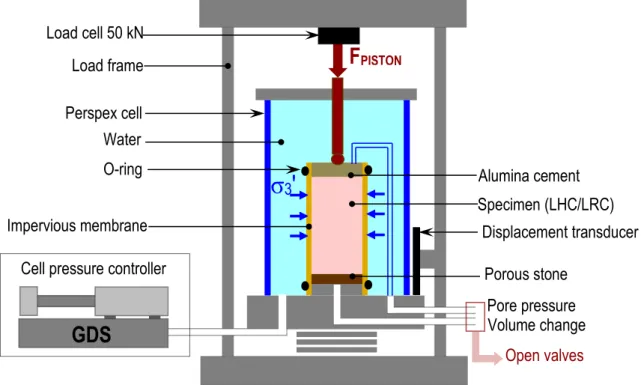
kPa, 100 kPa, 150 kPa) were applied and 3 or even 4 specimens were tested for each confining pressure. Fig. 2 shows a schematic representation of the triaxial test and the experimental conditions used to study the shearing of plant-based concretes. The equipment is composed of a load frame with a measuring device of the axial force (load cell of 50 kN with high accuracy of measurement), a triaxial cell that comes to be fixed on a speed-controlled platen with a piston that transmits the axial load to the concrete sample, a displacement transducer located on the moving platen (to measure the axial strain) and a cell pressure controller to set the confining pressure (σ3') in the cell (Fig. 2). All the data (load cell, axial strain and cell pressure) were collected by acquisition software.
Fig. 2. Schematic representation of the triaxial shear test on plant-based concretes
Specimens were put within an impervious membrane and sealing was preserved thanks to rubber O-rings (see Fig. 3a). The air drainage of the specimens was ensured by a porous stone positioned between their bottom and the moving platen (Fig. 2). In the present investigation dealing with the shearing of plant-based concretes, the drainage of unsaturated specimens at air pressure was performed by holding the valves open in order to simulate the actual configuration of a wall with a plant-based concrete (Fig. 2).
The cell was filled with tap water and pressurized to increase the confining pressure. The final assembly at the end of the set-up (water-filled cell in contact with
the load cell) is shown in Fig. 3b. Once the desired confinement achieved, the specimen was loaded axially with a constant confining pressure.
Displacement-controlled tests were conducted with a velocity fixed at 0.4 mm.min-1. The loading/disloading
cycle was performed at 2% strain in order to estimate the secant modulus.
Evaluation of shear strength parameters
In a conventional triaxial test, principal stresses are σ1', σ2' and σ3' with σ2' = σ3'. The mean effective
pressure (noted σm') is defined as follows (1):
Displacement transducer
Volume change
Pore pressure
Porous stone
Open valves
Impervious membrane
Alumina cement
Specimen (LHC/LRC)
σ
3
'
O-ring
Cell pressure controller
GDS
Load frame
Load cell 50 kN
F
PISTONPerspex cell
Water
σm' = σ1' + 2σ3 3' (1)
with σ1', the axial stress and σ3', the confining stress. Hence, the deviatoric stress (q = σ1'– σ3') is expressed
as follows (2):
σm' = q3 + σ3' (2)
Fig. 3 : (a) specimen with the impervious membrane and O-rings (b) Final assembly with the specimen
under confining pressure
The stress ratio represents the mobilized stresses for a given loading path. It can be determined for the peak deviatoric stress but also for higher rates of strain. It actually corresponds to the slope of the failure line in the (q – σm') diagram (M’ = q/σm'). It is then possible to
calculate the friction angle (φ) by the following relation (3):
φ = arcsin (M'+6)3M' (3) Thereafter, the cohesion (C) is expressed as follows (4):
C = C(φ) × (sinφM' ) (4) where C(φ) is the intercept of the linear regression in the (q – σm’) diagram, φ is the friction angle previously
calculated and M is the stress ratio.
3 RESULTS AND DISCUSSION
3.1 Porosity and density of plant-based concretes at the hardened state
The inter-particles porosity into the hardened concrete was calculated according to the following equation (5):
ηIP = (MA⁄ ) + [(MρA B × t)/ρSP]
VM
(5) where MA is the mass of plant aggregates introduced
in the mould, ρA is the apparent density of the particles,
MB is the mass of binder, t is the hydration degree of
the lime-based binder, taken as 1.1 [Tronet 2016], ρSP
is the specific density of the PF70 binder and VM is the
volume of the mould (1.39 L).
The total porosity (including voids within the particles) was calculated in the same manner by replacing the apparent density by the true density of the particles.
The results are reported in Tab. 3. The inter-particles porosity of LRC remains considerably higher than that of LHC. However, the total porosity of both plant-based concretes is close due to the high porosity within hemp shives. Since mix proportions are the same for LHC and LRC, the compactness of concretes (i.e. their void ratio) will be one of the key parameters for the shear behaviour.
Tab. 3: Porosities of plant-based concretes
Plant-based concrete Notationa %porosity
LHC ηIP 7.2
ηTOT 67.6
LRC ηIP 51.3
ηTOT 66.9
aηIP: inter-particles porosity, ηTOT: total porosity
The bulk density of specimens after 60 days of curing at 23°C and 65%RH is reported in Tab. 4. It is around 700 kg.m-3 for LHC and a bit higher for LRC.
Tab. 4: Bulk density expressed in kg.m-3
Plant-based concrete MVa Σb
LHC 697 4
LRC 727 6
aMV: Mean value, bΣ: Standard deviation
3.2 Density gradient
LHC/LRC specimens were sawn into 3 cylinders (n°1 for the upper part, n°3 for the lower part and n°2 for the mid cylinder) to evaluate the density gradient along their length due to the vibro-compaction process. The patterns are reported in Fig. 4.
Fig. 4: Deviation from average density of specimens
LHC clearly shows a significant density gradient. The deviation from the average density rises up to 7% in the upper part of the cylinder (Fig. 4). This is due to the compaction process in a single layer which generates friction along the walls of the moulds. By contrast, the density gradient of LRC can be considered as nearly non-existent. This is attributed to the lower compaction energy used to reach the target fresh density owing to the higher particle density of rice husk. As a result, the
③ ② ① 0 25 50 75 100 125 150 175 200 -10 -8 -6 -4 -2 0 2 4 6 8 10 Hei g h t (m m )
Deviation from average density (%) LHC LRC
frictional forces during the compaction process of LRC are significantly lower.
3.3 Unconfined compression
The results obtained from the unconfined compression are presented in Fig. 5. The stress-strain curve of LHC shows a more ductile behaviour. This confirms that the granular skeleton of hemp aggregates was much more compacted than that of rice husks. The closing of the inter-particles porosity of LHC in the fresh state results in the compression of a dense packing of shives with a high strain capacity at the hardened state (see Tab. 3). Moreover, a compressive strength of 2.47 ± 0.23 MPa is achieved for LHC whereas that of LRC is only 1.46 ± 0.18 MPa despite identical mix proportions. This can be attributed to the high inter-particles porosity in LRC and to the features of rice husks which provide a poor rearrangement of particles (narrow size distribution). A previous research had already highlighted the lower compressive strength of LRC compared to a manually tamped LHC [Chabannes 2015]. It had been attributed to the bonding strength between the lime-based binder and the aggregates. In fact, the granular stacking of plant aggregates has also to be considered.
0
2
4
6
8
10
0.0
0.5
1.0
1.5
2.0
2.5
LRC
Stress (MPa)
Rate of strain (%)
LHC
Fig. 5: Stress-Strain curves of specimens tested after 60 days of curing
Young’s modulus (ECYC) is thereafter reported in Tab.
5. As for compressive strength, it is lower for LRC.
Tab. 5: Young’s modulus of plant-based concretes
Plant-based concrete ECYC
LHC 236 ± 28
LRC 175 ± 30
3.4 Triaxial compression
Shear strength parameters
Mean values of the peak deviatoric stress (qP) for each
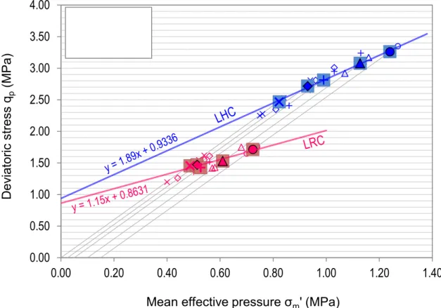
confining pressure (hence increased mean effective pressure) are plotted in Fig. 6 (qP – σm' diagram). An
increase in the peak deviatoric stress with increasing confining pressure is noted. This increase is greater for LHC (qP = 2.7 MPa for p’0 = 25 kPa and qP = 3.3 MPa
for p’0 = 150 kPa). It should be noted that the loading
capacity of LRC under shearing becomes sensitive to confinement for p’0 = 100 kPa.
The failure lines of bio-based concretes under shearing are given by a linear regression of the peak values (qP,
σm'). The peak friction angle (φP) and the cohesion (C)
are determined with equations (3) and (4) exposed before and reported in Tab. 6.
Tab. 6: Shear strength parameters (peak friction angle and cohesion)
Plant-based concrete φP(°) C(kPa)
LHC 46 355
LRC 29 362
Firstly, the peak friction angle of LHC (46°) is found to be higher than that of LRC (29°). However, both plant-based concretes show a same cohesion which is about 0.36 MPa (see Tab. 6). Based on the model used for ordinary concrete or even sands and clays reinforced by cement grouting [Zingg 2016 and Maalej 2007], the friction angle is more willingly related to the granular skeleton (i.e. the interlocking of the plant aggregates) whereas the cohesion is rather due to cementation and bonding between the binder and the aggregates. From this standpoint, a close link between the strength of the lime-based binder and the cohesion is assumed. The binder content (B/A = 2.3) and the W/B mass ratio are the same for both types of concrete. This is probably the reason why their failure lines cross each other at the intercept. For instance, Maalej et al. [Maalej 2007] have shown that cohesion is proportional to the volume fraction of cement in grouted sands. With regard to the peak friction angle, several parameters need to be taken into consideration. One might think that the latter is negatively affected by the high inter-granular void ratio of LRC (reported in Tab. 3). Moreover, particle size distribution has also a great effect on the friction angle. The size range of hemp shives is assumed to provide a better aggregate packing thus contributing to the shear strength of LHC. The very different shape of the particles (i.e. thin semi-ellipsoidal husk versus thick parallelepipedic shiv), their rigidity and their surface properties (like roughness) are also inherent features which could benefit to the friction angle of LHC. To the best of our knowledge, no studies have been made about the frictional properties of unbound hemp shives and rice husks. For instance, the study of Aloufi and Santamarina deals with the mechanical behaviour of rice grains under triaxial compression [Aloufi 1995]. However, some authors reported the effective friction angle of woodchips measured with the direct shear box test. One may say that morphology, size grading and rigidity of woodchips can be considered as close to those of hemp shives. The difference lies in the bulk density (from 200 to 300 kg.m-3 regarding woodchips
[Wu 2011]) and the internal porosity. Stasiak et al. [Stasiak 2015] report an effective friction angle of 42° whereas the values of Wu et al. [Wu 2011] are in the range of 44° to 54° depending on moisture content and particle size distribution. These results correspond to the internal friction angle of unbound woodchips and should be compared to the friction angle calculated at large strains in the triaxial test (i.e. when the binder does not provide any more cohesion).
Fig. 6: Peak shear strength of plant-based concretes in q–σm’ coordinate system
The critical state friction angle is an intrinsic variable that is not dependent on the initial state and the stress path. It is often used to describe the shear strength of soils. In theory, it can be determined when the stress ratio (q/σm') is constant while shear strain continues to
increase. Unfortunately, the samples do not reach the critical state within the strain limits of the test due to their high ductility. The peak is reached for high strains and the post-peak strain softening never ends up. This lead us into the issue of the high compressibility of these materials compared to those based on mineral aggregates. Investigations could be performed on the bulk modulus of plant-based concretes. In addition, it should be noted that, in spite of the great deformability of the plant aggregates, membrane perforation was identified at the end of some tests at a confinement of 150 kPa (with a strain over than 20%).
Deviatoric behaviour and failure mode
For the vast majority of specimens (whether for LHC or LRC), one observes a significant evolution towards a deviatoric behaviour (deviatoric stress vs. axial strain) with a stronger ductility when the confining pressure increases. The effect of confining pressure on the rate of strain at failure (peak shear strength) is analysed in Fig. 7. For LHC, the strain capacity at failure rises from 6% (unconfined compression) to 19% (p’0 = 150 kPa).
Fig. 7 shows that strain capacity of LHC is higher than that of LRC. However, the increase in this rate of strain at peak stress with rising confining pressures is of the same size for both concretes. The increase in ductility due to the confinement occurs predominantly beyond a confining pressure of 50 kPa for LRC.
As regards LHC, for high confining pressures, some specimens exhibit a more brittle behaviour (lower rate of strain at failure and higher elastic modulus than the
other ones). These specimens correspond to outliers in Fig. 7 and show a failure mode with a localized shear band (FM1 in Fig. 8a). However, this kind of failure only concerns a very small number of LHC specimens. Actually, most of them rather show localized bulging and crushing in their lower part (FM2 in Fig. 8b). The shear failure surface is thus practically invisible. For all the specimens that show this kind of failure, the strain capacity is very important when the confining pressure is high (Fig. 7).
Fig. 7: Effect of confining pressure on the rate of strain at failure
0.00
0.50
1.00
1.50
2.00
2.50
3.00
3.50
4.00
0.00
0.20
0.40
0.60
0.80
1.00
1.20
1.40
Dev
iat
ori
c st
ress
q
p(M
Pa
)
Mean effective pressure
σ
m' (MPa)
0
5
10
15
20
25
0
25
50
75 100 125 150
Rat e o f s tra in a t fa ilu re (% )Effective confining pressure p’0(kPa) LHC
LHC Outliers LRC LRC Outlier
Fig. 8: Failure patterns of specimens: shear banding (a) & (c), bulging failure (b) & (d)
An interesting outcome of the post-test observations is the failure mode of LRC which corresponds to shear banding for all specimens except for one (over the 12 specimens tested). The associated failure pattern is represented in Fig. 8c. The consistency of this failure mode (FM1) for LRC is higher than that of the bulging mode (FM2) for LHC. Among LRC specimens, the only one that exhibits bulging (Fig. 8d) shows a pronounced strain hardening and a rate of strain at failure of almost 18% (LRC outlier in Fig. 7). This level of ductility is not achieved for other specimens.
In the field of granular materials, when a specimen is subjected to triaxial compression, it fails with either a localized shear plane or a bulging shape. In this study, shear banding is the most consistent failure mode for LRC. It should be noted that the failure occurs across the lower half of the specimens (Fig. 13c). As regards LHC, bulging is more frequently observed but failure probably results from a combination of shear banding (not well defined) and bulging for many specimens. The occurrence of one or another kind of failure mode has to be analysed. According to some authors [Ma 2016 and Kumruzzaman 2012], both failure mode and shear band formation depend on porosity, particle size and shape, specimen density and confining pressure. In the present study, the density gradient of specimens is assumed to be responsible for bulging and crushing in the lower part of LHC specimens since it involves a non-uniform pore distribution into the specimen. The densification of the lower part of the specimen and the high compressibility of hemp shives lead to large strain capacity with localized lateral expansion. This is in line with what has been observed in granular materials for which the contractive response (densification) is typical of a ductile behaviour. The pore distribution in LRC specimens is much more homogeneous as the density can be considered as uniformly distributed (see Fig. 4). This can partially explain the consistency of the shear banding for LRC. In addition, inherent properties of rice husk, particle size distribution and void ratio between
the particles provide a less ductile behaviour to LRC compared to that of LHC. This is already the case for unconfined compression (Fig. 5). Therefore, the peak shear strength is achieved for lower strains (Fig. 7) and a dilative response occurs during the strain softening stage. This response is accompanied by the formation of a shear band.
The occurrence of both failure modes for a same plant-based concrete is much more difficult to explain. It can be related to the level of confining pressure or also test conditions. The bulging in the lower part of specimens could be due to the edge effect induced by alumina cement on the top surfaces (in particular for LRC since the density gradient is not valid).
Young’s modulus
The Young’s modulus is plotted against the confining pressure in Fig. 9.
Since it proves to be sensitive to the failure mode of specimens, the only way to investigate the effect of the confining pressure on ECYC is to consider its values on
a case-by-case basis. As expected, the modulus of the LHC specimens for which shear banding (FM1) clearly occurs is significantly higher than that reported for the other ones. Moreover, some LHC specimens for which shear banding is not necessarily visible also exhibit a high modulus (for p’0 = 25 and 50 kPa). By contrast,
when pure bulging occurs (FM2), a particularly low modulus is measured. Between these two extremes, an intermediate modulus corresponds to a failure that combines both shear banding and bulging (FM1/2 in Fig. 9). Therefore, three groups are represented in Fig. 9. This also applies for LRC even if all specimens are concerned by the FM1 except one. These results show that in the case of non-uniform density along the length of the specimens, the modulus is that of the weaker part of the specimen (with a higher void ratio). For a given failure mode, ECYC seems to vary linearly with p’0
as is the case for granular materials. The modulus of LRC remains lower than that of LHC but this is not surprising in view of the mechanical behaviour of the
LHC
LRC
(a)
(b)
(c)
(d)
BANDING
BULGING
plant-based concretes under unconfined compression. The comparison of the evolution of ECYC should not be
performed between the two bio-based concretes given the poor number of LHC specimens concerned by the FM1 and the rather low correlation coefficient for LRC.
Fig. 9: Effect of confining pressure on ECYC
4 CONCLUSION
This experimental investigation is one of the first, if not the first (using triaxial compression), to deal with the shear behaviour of plant-based concretes. The key findings that emerged from this work are the following: ● The compressive strength of LRC is lower than that of LHC even though a same mix proportioning is used for both plant-based concretes. The packing of rice husks could be enhanced by increasing the rice husk content in the plant-based concrete.
● Under triaxial compression, the strain capacity (i.e. the ductility) of the specimens increases with confining pressure. However, ductility and elastic modulus are strongly impacted by the failure mode of specimens under the shear loading. In most cases, the failure mode of LHC is a combination of bulging localized in the lower part of the specimens and shear banding. When banding prevails on bulging, the mechanical behaviour of LHC is more brittle and the modulus is much higher. LRC exhibits a higher consistency of the failure mode which corresponds to shear banding in virtually all specimens. Therefore, it is assumed that bulging of LHC is mainly due to the non-uniform pore distribution along the length of the specimens.
● Plant-based concretes show a same cohesion (0.36 MPa) but the peak friction angle of LHC (46°) proves to be higher than that of LRC (29°). The cohesion seems to be correlated with the binder strength. Furthermore, this study highlights the predominant influence of the aggregate type on the peak friction angle. Inherent features of plant aggregates (size, shape, roughness, stiffness), inter-granular void ratio and manner that particles are packed probably all have a certain role to play in achieving lower shear strength for LRC. This will be further discussed by studying the relationships
between the mix proportioning and the shear strength of bio-based concretes.
● The strain capacity of plant-based concretes is such that specimens do not reach the critical state within the strain limits of the triaxial test used in the present work. Studying mixes with a lower binder-on-aggregate mass ratio is likely to be an issue since compressibility will further increase.
5 ACKNOWLEDGMENTS
The authors would like to thank Guillaume Potier and Michael D’Helft for their help in the experimental work.
6 REFERENCES
[Nguyen 2010] Nguyen, T.T.; Contribution à l’étude de la formulation et du procédé de fabrication d’éléments de construction en béton de chanvre. Université de Bretagne-Sud, 2010.
[Tronet 2016] Tronet, P.; Lecompte, T.; Picandet, V.; Baley C.; Study of lime hemp concrete (LHC) – Mix design, casting process and mechanical behaviour; Cement and Concrete Composites, 2016, 67, 60-72. [Dinh 2014] Dinh, T.; Contribution au développement du béton de chanvre préfabriqué utilisant un liant pouzzolanique innovant. Université de Toulouse, 2014. [Munoz 2013] Munoz, P. and Pipet, D.; Plant-based concretes in structures: structural aspect-addition of a wooden support to absorb the strain: in Amziane, S.; Arnaud, L.; Bio-aggregate-based building materials, Wiley-ISTE, 2013.
[Gross 2014] Gross, C. and Walker, P.; Racking performance of timber studwork and hemp-lime walling; Construction and Building Materials, 2014, 66, 429-435.
[Chabannes 2015] Chabannes, M.; Formulation et étude des propriétés mécaniques d’agrobétons légers isolants à base de balles de riz et de chènevotte pour l’éco-construction. Université de Montpellier, 2015. [Zingg 2016] Zingg, L.; Briffaut, M.; Baroth, J.; Malecot, Y.; Influence of cement matrix porosity on the triaxial behaviour of concrete; Cement and Concrete Reasearch, 2016, 80, 52-59.
[Maalej 2007] Maalej, Y.; Dormieux, J.; Canou, J.; Dupla J-C.; Strength of a granular medium reinforced by cement grouting. Comptes Rendus Mécanique, Elsevier Masson, 2007, 335 (2), 87-92.
[Wu 2011] Wu, M.R.; Schott, D.L.; Lodewijks, G.; Physical properties of solid biomass; Biomass and bioenergy, 2011, 35, 2093-2105.
[Stasiak 2015] Stasiak, M.; Molenda, M.; Banda, M.; Gondek, E.; Mechanical properties of sawdust and woodchips; Fuel, 2015, 159, 900-908.
[Ma 2016] Ma, G.; Zhou, W.; Chang, X.L.; Ng, T.T. et al.; Formation of shear bands in crushable and irregularly shaped granular materials and the associated microstructural evolution; Powder Technology, 2016, 301, 118-130.
[Kumruzzaman 2012] Kumruzzaman, M.; Yin, J.H.; Stress-strain behaviour of completely decomposed granite in both triaxial and plane strain conditions; Jordan journal of civil engineering, 2012, 6-1.
0 50 100 150 200 250 300 350 0 50 100 150 200 ECY C (M Pa )
Effective confining pressure p’0(kPa)
LHC-FM1 LHC-FM1/2 LHC-FM2 LRC-FM1 LRC-FM2