HAL Id: hal-02106038
https://hal.univ-lorraine.fr/hal-02106038
Submitted on 10 May 2019
HAL is a multi-disciplinary open access
archive for the deposit and dissemination of
sci-entific research documents, whether they are
pub-lished or not. The documents may come from
teaching and research institutions in France or
L’archive ouverte pluridisciplinaire HAL, est
destinée au dépôt et à la diffusion de documents
scientifiques de niveau recherche, publiés ou non,
émanant des établissements d’enseignement et de
recherche français ou étrangers, des laboratoires
Carbonitriding of low alloy steels: Mechanical and
metallurgical responses
Walter Dal’Maz Silva, Jacky Dulcy, Jaafar Ghanbaja, Abdelkrim Redjaimia,
G. Michel, S. Thibault, T. Belmonte
To cite this version:
Walter Dal’Maz Silva, Jacky Dulcy, Jaafar Ghanbaja, Abdelkrim Redjaimia, G. Michel, et al..
Car-bonitriding of low alloy steels: Mechanical and metallurgical responses. Materials Science and
Engi-neering: A, Elsevier, 2017, 693, pp.225-232. �10.1016/j.msea.2017.03.077�. �hal-02106038�
Carbonitriding of low alloy steels: mechanical and metallurgical responses
W. Dal’Maz Silvaa,b,∗, J. Dulcya,∗, J. Ghanbajaa, A. Redjaïmiaa, G. Michelb, S. Thibaultc, T. Belmontea,∗∗
aInstitut Jean Lamour - UMR CNRS-Université de Lorraine 7198, Parc de Saurupt, Nancy 54011, France bInstitut de Recherche Technologique M2P, Metz 57070, France
cSafran Tech, Magny les Hameaux, France
Abstract
Metallurgical and mechanical responses to the introduction of carbon and/or nitrogen have been investigated for alloys 16NiCrMo13 and 23MnCrMo5 through atmospheric pressure carbonitriding, carburizing and austenitic nitriding.
Treatments were performed at 1173 K using CO − H2 and/or NH3 based atmospheres. As-quenched hardness is
studied in terms of solid solution interstitial content, which is estimated from electron probe micro-analyses and thermodynamic simulations. This aims to quantify high-temperature precipitation of nitrides, which is accompanied by consumption of nitrogen in solid solution. Plots of as-quenched hardness versus the square root of the total content expressed in atomic fraction of interstitial elements, i.e. the sum of solution carbon and nitrogen, show the complementary character of these elements in determining the mechanical properties of the as-quenched alloys. Tempering of carbon-nitrogen martensite – for both carbonitriding and austenitic nitriding – led to lower hardness loss when compared to the same total content of interstitial carbon in martensite. Transmission electron microscopy
analyses highlight precipitation of fine Fe16N2zones in the nitrogen-rich depth.
Keywords: hardness measurement, martensite, steel, precipitation
Introduction
Carbonitriding is an austenitic field case hardening process generally conducted from 1073 K to 1173 K [1, 2] through the introduction of carbon and nitrogen into iron, low-carbon low-alloy steels and powder metal-lurgy parts. It is often performed on power transmis-sion parts, such as gears, which are submitted to struc-tural and surface fatigue operating conditions. Aim-ing at the required properties, carbonitrided parts are quenched [3] to outcome the strain energy required by martensite transformation [4]. This leads to a hard and brittle lath martensite microstructure, which is typically tempered prior to application. Thus, the understanding of attainable mechanical properties is based on
carbon-∗Corresponding author ∗∗Principal corresponding author
Email addresses:
walter.dal-maz-silva@univ-lorraine.fr(W. Dal’Maz Silva), jacky.dulcy@univ-lorraine.fr (J. Dulcy), jaafar.ghanbaja@univ-lorraine.fr(J. Ghanbaja), abdelkrim.redjaimia@univ-lorraine.fr(A. Redjaïmia), gregory.michel@irt-m2p.fr(G. Michel),
simon.thibault@safran.fr(S. Thibault),
thierry.belmonte@univ-lorraine.fr(T. Belmonte)
nitrogen martensite behavior. Conversely to nitrogen ef-fects [5, 6], much has been reported about the role of carbon on martensite transformation of steels [7]. For nitrogen martensite, literature remains mostly limited to the Fe-N system, for which metallurgical transforma-tions through tempering and room temperature aging are established [8–15]. Although the as-quenched be-havior of carbon martensite can be readily described in terms of interstitial content [7, 16–18], nitrogen effects are not often reported. It has been proposed that for typ-ical treatment durations, precipitation of nitrides does not reach the equilibrium fractions computed with some of the currently available thermodynamic databases [5]. Thus, elemental partitioning [19] between matrix and nitrides formed during alloy enrichment plays a role on the nature and fractions of possible phases formed during tempering, leading to a series of more com-plex mechanisms which will be discussed throughout the text. Intending to explore metallurgical responses rather than process parameters, which may be found in reference papers [1, 20], this work focuses on carboni-triding as a sequence of carburizing and nicarboni-triding steps, even though simultaneous enrichment in both interstitial elements is the long-term established industrial practice
of atmospheric process. Nitrogen solubility at treatment temperature is drastically reduced by the presence of al-loying elements such as chromium and manganese and precipitation of nitrides takes place already during en-richment. Thus, the effective nitrogen hardening effect is linked to the reminiscent interstitial nitrogen, which also reduces the critical cooling rate for quenching, leading to a more consistent martensite transformation. Experimental studies supported by Thermo-Calc [21] thermodynamic simulations of steels composition af-ter treatments were conducted. Hardening responses to carburizing and austenitic nitriding are compared to carbonitriding results. Diffusion profiles are correlated with local hardness and microstructure. Dictra [21, 22] simulations are used for predicting MN-nitrides precipi-tation along the diffusion profile, thus, incorporating ni-trogen in the as-quenched hardness model [16, 17]. 1. Experimental methods
1.1. Treatment parameters
Metallurgical responses to thermochemical treat-ments – carburizing, austenitic nitriding and car-bonitriding – of alloys given in Tab. 1 are studied. Specimens with dimensions of 40 mm × 14 mm × 4 mm taken from wrought bars are polished up to 1200 grit sandpaper prior to enrichment. Processing is then car-ried out in a vertical flow reactor with diameter of 50 mm and 100 mm isothermal length at the setup tem-perature. Since the studied alloys do not contain inten-tionally added grain growth stabilizers, in order to opti-mize process kinetics without compromising austenitic grain size [23], a temperature of 1173 K is adopted for all treatments. Heating is carried out under inert
atmosphere consisting of N2 − 0.2 H2 with total flow
rate of 500 cm3min−1. A carburizing atmosphere based
on CO − H2, controlled through dew point
measure-ment [24], has been designed to promote carbon surface saturation. Nitrogen enrichment is conducted through an ammonia/cracked ammonia atmosphere. Diffusion steps as well as tempering times and temperatures are given in Tab. 2. After treatment, samples are immedi-ately oil quenched (298 K) and submitted to cryogenic treatment in boiling nitrogen (77 K). Tempering is then conducted under the same atmosphere employed during heating stage.
1.2. Materials characterization
Treated samples are cross-sectioned and epoxy resin hot mounted prior to analysis. Grinding is followed by progressive alumina polishing until particle size below
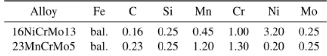
Table 1: Nominal composition of the studied alloys (wt.%).
Alloy Fe C Si Mn Cr Ni Mo 16NiCrMo13 bal. 0.16 0.25 0.45 1.00 3.20 0.25 23MnCrMo5 bal. 0.23 0.25 1.20 1.30 0.20 0.25
0.5µm. Visible-light microscopy (VLM) assessment of
microstructure and mechanical property measurement through Vickers micro-hardness testing under a load of 300 gf (HV0.3) are carried out. Chemical micro-analyses of diffusion profiles are conducted through Jeol JXA-8530F electron probe micro analyzer (EPMA) us-ing the same calibration techniques described by Cat-teau et al. [5]. Identification of both high and low temperature precipitates, i.e. those formed during en-richment and those formed during temper, respectively, is realized through transmission electron microscopy (TEM) using a Jeol ARM-200F equipment operating at 200 kV. High temperature precipitates composition and distributions are identified semi-quantitatively by energy dispersion x-ray spectroscopy (EDS). Precipi-tates structure is identified by electron diffraction. 2. Results
Effects of cryogenic treatment over retained
austen-ite (γr) decomposition after carbonitriding of alloy
16NiCrMo13 are presented in Fig. 1, showing equiva-lent regions before and after cryogenic treatment along with local composition. This representation is proposed
in order to provide understanding of γrcontent in terms
of interstitial elements mass fractions and will later be related to the H-point composition [15]. Quantifica-tion by VLM image analysis in the cross-secQuantifica-tion gives
a fraction of γr around 35% in the region comprised
between the surface and a depth of 200µm. Figure 3
summarizes measured as well as simulated diffusion profiles for all treatment setups. Under the same op-erating conditions, i.e. same nitriding potential [25], surface nitrogen for alloy 16NiCrMo13 did not reach 0.4 wt.% N while alloy 23MnCrMo5 exceeds 0.6 wt.% N. Carbonitrided samples of both materials show the same carbon profile shape but with reasonably lower surface content than the simulated values. A similar surface carbon decrease is observed in nitrided samples, remarkably for alloy 23MnCrMo5 due to its higher ini-tial content, without any accumulation peak toward the core. Experimental composition profiles are then used as input for local equilibrium computations at enrich-ment temperatures using Thermo-Calc [21] database TCFE7. Such simulations provide the total solid
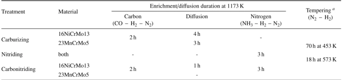
solu-Table 2: Treatment durations for carburizing, austenitic nitriding and carbonitriding.
Treatment Material Enrichment/diffusion duration at 1173 K Temperinga
(N2−H2) Carbon (CO − H2−N2) Diffusion Nitrogen (NH3−H2−N2) Carburizing 16NiCrMo13 2 h 4 h -70 h at 453 K 18 h at 573 K 23MnCrMo5 3 h Nitriding both - - 3 h Carbonitriding 16NiCrMo13 2 h 1 h 3 h 23MnCrMo5
-aNitrided samples were also tempered during 18 h at 673 K.
tion atomic fraction xifor carbon and nitrogen, which
is then used to plot hardness – in the as-quenched and
after cryogenic treatment conditions – versus x0.5
i , the
square root of this quantity, as shown in Fig. 4. This method makes no distinction between treatments since it is resorted to evidence the complementary character of interstitial elements. Three distinct behaviors are de-picted in Fig. 4: (i) a linear dependence of hardness with
xiup to a value of 0.16 (corresponding to around
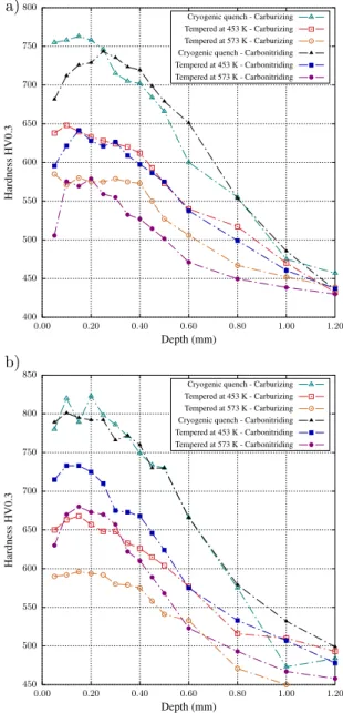
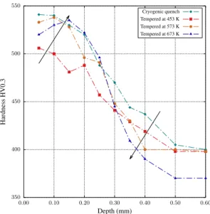
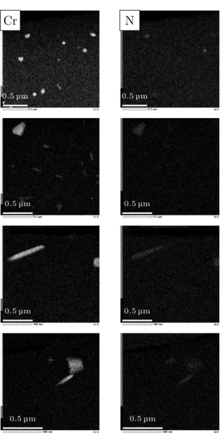
0.55-0.60 wt.% of interstitials) which is followed by (ii) a hardening plateau until around 0.19 (0.90 wt.% of in-terstitials) and then (iii) a strong hardness decrease for higher contents. These points beyond the so-called H-point were obtained from high carbon samples, which were quenched directly after enrichment for illustra-tion purposes and correspond to the microstructure pre-sented in Fig. 1. Next, Fig. 5 shows the tempering be-havior of the cryogenic quenched samples with diffu-sion profiles given in Fig. 3 - except for nitrided sam-ples, which are discussed apart. For alloy 16NiCrMo13 the maximum hardness attained by cryogenic quenching was around 750 HV0.3 while for alloy 23MnCrMo5, hardening reached 800 HV0.3. These start-points are presented together with hardness profiles for samples tempered at both 453 K and 573 K. Hardness profiles for nitrided samples are presented in Fig. 6 to better depict the abnormal tempering effect observed for this treatment: hardness is kept close to the as-quenched level in the nitrogen-rich zone if tempering is carried out above 573 K, while at 453 K hardness decreases as a whole. The reported mechanical responses are then studied by transmission electron microscopy. Figure 7 presents chemical maps of sub-micrometric precipitates observed in a foil taken at 0.2 mm from the treated sur-face of alloy 23MnCrMo5 after carbonitriding. These maps present the main elements found to compose the precipitates, which include nitrogen, chromium, man-ganese and silicon. On the other hand, precipitates
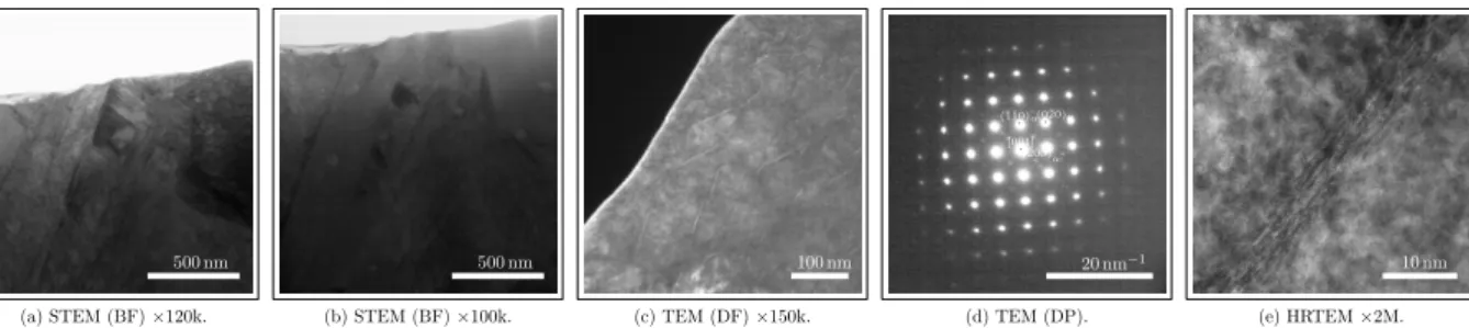
formed at enrichment temperatures during nitriding and carbonitriding for alloy 16NiCrMo13 show only signif-icant amounts of nitrogen and chromium (Fig. 8). Fi-nally, the abnormal behavior observed after tempering nitrided specimens of alloy 16NiCrMo13 is depicted in Fig. 6. It is studied by comparing the reference as-quenched state microstructure (Fig. 9) with the sam-ple tempered at 573 K (Fig. 10), comprising standard transmission micrographs, diffraction patterns (DP) and high resolution microscopy (HRTEM). Although both Fig. 9d and Fig. 10b present similar diffraction patterns
corresponding to Fe16N2precipitates, different sizes and
morphologies are observed. 3. Discussion
Before proceeding with the analyses of diffusion pro-files and their influence over mechanical properties, some knowledge about the equilibrium phases at en-richment temperature (1173 K) is desirable. Thermo-Calc [21] was used for the simulation of pseudo-equilibrium isothermal sections in terms of carbon and nitrogen contents. Using database TCFE7, carbon satu-ration at ∼ 1.0 wt.% is predicted for both alloys, above
which M3C is the equilibrium carbide, as reported for
some of the ternary and quaternary systems closely re-lated to the studied alloys [26–28]. The threshold for precipitation of nitrides is found around 0.10 wt.% N in the absence of carbon and decreased slightly to 0.08 wt.% N at carbon saturation. Since these computa-tions are performed considering all the elements listed in Tab. 1, diagrams tie-lines are not in the calculation plane and thus, these limits for precipitation of carbides and nitrides are just thresholds above which further sol-ubility of interstitials is still possible. To illustrate this, Fig. 2 presents the content of nitrogen in solid solution along with MN nitride volume fraction in terms of total nitrogen content. Increasing the nitrogen content above
200µm 200µm 0.89 %wt C 0.84 %wt C 0.82 %wt C 0.81 %wt C 0.78 %wt C 0.77 %wt C 0.74 %wt C 0.70 %wt C 0.10 %wt N 0.19 %wt N 0.18 %wt N 0.09 %wt N 0.08 %wt N
Figure 1: Visible light micrographs of alloy 16NiCrMo13, surface en-riched with around 0.90 wt.% C and 0.10 wt.% N, after (a) oil quench and (b) cryogenic treatment. Local composition along the profile is shown in figure. Magnification of 200×.
the precipitation threshold leads to increasing the nitro-gen solubility: the alloy behavior approaches the iron-like solubility limit due to the depletion of alloying el-ements from the matrix. Simulations show that up to a certain limit (below 0.5 wt.% N in the range of car-bon contents achieved in the present work), only MN
(M = Cr, Mo) nitrides are present, while higher
con-tents lead to the precipitation of Si3N4, as expected in
the iron-rich corner for the Fe-Si-N system [29]. Pre-cipitation is accompanied by the depletion of alloying elements from the matrix, leading to increased nitro-gen solubility, i.e. the austenitic matrix tends towards the Fe-N system behavior. Due to their size – sub-micrometer scale – and morphology kinetically favored by treatment temperature, these nitrides are incoherent with the matrix and do not represent a dislocation glide barrier.
3.1. Diffusion profiles
Figure 3 presents the intricate behavior of carbon and nitrogen diffusing simultaneously during carbonitriding
0, 000 0, 002 0, 004 0, 006 0, 008 0, 010 0, 012 0, 014 0, 000 0, 002 0, 004 0, 006 0, 008 0, 010 0, 012 0, 0140, 000 0, 002 0, 004 0, 006 0, 008 0, 010 0, 012 0, 014 0, 016 Fraction massique de azote en solution solide γ Fraction massique de nitrures MN
Fraction massique en azote
Nγ-16NiCrMo13 Nγ-23MnCrMo5 MN-16NiCrMo13 MN-23MnCrMo5
Figure 2: Content of nitrogen in solid solution and volume fraction of nitrides in terms of total nitrogen content for alloys 16NiCrMo13 and 23MnCrMo5. Simulations were carried out with Thermo-Calc, database TCFE7.
and austenitic nitriding when compared with the single-phase diffusion of carbon during carburizing. Process-ing conditions led to diffusion profiles in good agree-ment with Dictra [21, 22] simulations for carburizing. On the other hand, carbonitriding is not properly mod-eled simply by constant surface activity boundary con-ditions derived from atmosphere thermodynamics, i.e. saturation activity for carbon and atmosphere nitrogen activity. The carbon maximum observed for both alloys in the carbonitriding simulations around 0.3 mm from the surface is mostly related to repulsion of intersti-tial elements between themselves, i.e. carbon-carbon, nitrogen-nitrogen and nitrogen-carbon negative inter-acting energies, but also by the precipitation of nitrides during enrichment and de-carburizing during nitriding, evidenced by gas chromatography with the formation of methane. Based on the measurement of this hydrocar-bon output, surface reaction rate is estimated and imple-mented as boundary condition for carbon back-flow in order to properly simulate carbonitriding diffusion pro-files. Carbon-carbon repulsion behavior is well known and reported in the literature [30–33]. In order to al-low the simulation of such phenomenon and the inter-actions between alloying elements and interstitials, On-sager [34, 35] linear approach for irreversible thermo-dynamics is taken into account by Dictra [21, 22]. Rea-sonably similar results may be achieved by integrating the time-dependent diffusion equation following the
ap-proach given by Slycke and Ericsson [2] for the Fe-C-N system. This approach takes into account the de-pendencies of the diffusion coefficients with interstitial contents only through a geometric exclusion formalism. This implies that for low alloy steels, interaction ener-gies amongst interstitials are much higher than with al-loying elements, which play a major role only on block-ing diffusion by formation of precipitates. Usblock-ing the composition-independent carbon diffusion coefficient in austenite supplied by Slycke and Ericsson [2], it can be shown, for instance, with a Crank-Nicolson [36] scheme solution of the diffusion equation, that the pre-exponential factor needs to be multiplied by a factor of 1.8-2.0 in order to produce the same mass intake as Dic-tra [21, 22] simulated values. This is in agreement with a discussion by Bhadeshia [30]. It means that C-C in-teractions can almost double the carbon diffusion coef-ficient with respect to its infinite dilution limit, i.e. in absence of carbon.
Measurements of residual ammonia at reactor outlet allow the computation of nitrogen activity around value
aN= 40, by taking atmospheric pressure N2as the
refer-ence state and equilibrium expressions given by Slycke and Ericsson [1]. This value was initially used for estab-lishing the boundary condition for nitriding steps simu-lations, reasonably representing nitrogen profiles for al-loy 23MnCrMo5. Regarding alal-loy 16NiCrMo13, this activity does not allow proper simulation of diffusion profiles, which are best fit by a nitrogen activity in the order of 10. This is probably due to the catalytic effect of nickel favoring the recombination of adsorbed
nitro-gen atoms and formation of N2or other gas phase
prod-ucts. Due to this deviation, nitrogen in solid solution is computed from the actual measured total nitrogen con-tent in order to be incorporated in the hardening model. 3.2. As-quenched hardness
Hardness profiles of as-quenched martensite pre-sented in Fig. 5 agree with typical reported values [7, 18, 37, 38] for plain iron and low-alloy steels. Although this property is dependent on several factors such as marten-site morphology, solid solution hardening and disloca-tion density and mobility [7], its strongest dependence lays on interstitial content, allowing direct comparison amongst iron-based materials [18, 37]. For instance, Hutchinson et al. [18] show that for Fe-1.7Mn-0.23Si-0.12C and Fe-1.7Mn-0.21Cr-0.23Si-0.23C steels, the contribution of base alloying elements represents 10-12% of the yield strength, while grain size corresponds to about 13%, dislocations to 12-13%, martensite struc-ture to 35-39% and interstitial atoms to 61-66%. It is assumed that the authors [18] reasoning was based on
400 450 500 550 600 650 700 750 800 0.00 0.20 0.40 0.60 0.80 1.00 1.20 H ar dn es s H V 0. 3 Depth (mm)
Cryogenic quench - Carburizing Tempered at 453 K - Carburizing Tempered at 573 K - Carburizing Cryogenic quench - Carbonitriding Tempered at 453 K - Carbonitriding Tempered at 573 K - Carbonitriding 450 500 550 600 650 700 750 800 850 0.00 0.20 0.40 0.60 0.80 1.00 1.20 H ar dn es s H V 0. 3 Depth (mm)
Cryogenic quench - Carburizing Tempered at 453 K - Carburizing Tempered at 573 K - Carburizing Cryogenic quench - Carbonitriding Tempered at 453 K - Carbonitriding Tempered at 573 K - Carbonitriding a)
b)
Figure 3: Carbon and nitrogen diffusion profiles: (a) al-loy16NiCrMo13 and (b) alloy 23MnCrMo5. Full lines with same color as dotted lines represent the simulated profiles. Simulations were carried out with Dictra, databases TCFE7 and MOBFE2.
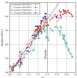
the idea that interstitial atoms behave as if they were solid solution clusters, blocking dislocation movement thanks to precipitates, and thus contributing to strength-ening by a square-root dependence on their content [39]. Results by Morito et al. [40] show a linear dependence of dislocation density on carbon content. Since dis-location forest strengthening is also represented by a square-root law versus dislocation density, this term in the total strengthening also obeys a square-root depen-dence with interstitial content [7, 16–18]. We specu-late that a similar behavior may be attributed to nitrogen in solid solution below what is known as the H-point, i.e. the composition at which BCC to BCT martensite transition occurs, accompanied by retention of austen-ite, since it happens at the same atomic fraction for both carbon and nitrogen [15]. Thus, the relationship pro-posed by Norstrom [17] may be generalized by consid-ering the total mole fraction xi of solid solution carbon and nitrogen, i.e. the amounts of these elements that are not under the form of precipitates. These assump-tions made, the knowledge of actual nitrogen in solid solution is necessary so that this element may be in-troduced in the model. Thermo-Calc [21] was used in the computation of the total interstitial mole fraction at each point where chemical microanalysis has been per-formed. Other contributions, such as depletion of alloy-ing elements from the matrix or changes in martensite structure were considered irrelevant based on the dis-cussion above. Figure 4 presents the plot of hardness versus x0.5
i . Such behavior for both elements seems
log-ical if we consider the dislocation blocking in terms of clusters of interstitials, which must increase with the relative number of interstitial atoms in the structure, since the number of barriers to dislocation movement is the actual variable governing hardness [39]. Fur-thermore, as depicted by Yahia [41], the size of nitro-gen in austenite is only about of 5-7% larger than car-bon, thus, on the average it is expected a close block-ing effect for both elements. An exhaustive study could possibly allow the introduction of a coefficient for rel-ative nitrogen effect, thus refining this model. Two main regions characterize plots in Fig. 4, the first for which hardness increases linearly with increasing
pa-rameter x0.5
i followed by hardening plateau. A straight
line is added in order to highlight the zone where pro-portionality prevails, which has its upper boundary at
x0.5i = 0.16 before cryogenic treatment. This value may
roughly be converted to wC+ wN = 0.0055 (0.55 wt.%),
above which no surface improvement may be achieved with room temperature oil-quench, corresponding to the well-known H-point [15]. A third zone may be
con-sidered for highly enriched zones (above x0.5
i = 0.18) 400 500 600 700 800 900 0.08 0.10 0.12 0.14 0.16 0.18 0.20 0.22 H -p oi nt H ar dn es s H V 0. 3 x0.5 i As-quenched 16NiCrMo13 Cryogenic 16NiCrMo13 As-quenched 23MnCrMo5 Cryogenic 23MnCrMo5
Figure 4: Validity of adopted hardening model below the H-point for alloys 16NiCrMo13 and 23MnCrMo5.
at which hardness drastically decreases due to the fast
growth in the amount of γr[15]. The decomposition of
γr with cryogenic treatment is brought to light for
al-loy 16NiCrMo13 in Fig. 4 by the increase in hardness produced by its transformation into martensite. No such phenomenon has been observed for alloy 23MnCrMo5 since it has not been enriched to high levels of intersti-tials.
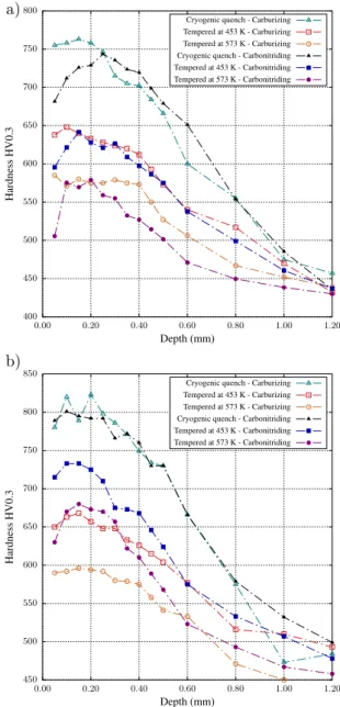
3.3. Tempering effects
While the as-quenched hardness may be explained in terms of interstitial content, tempering produces a se-ries of more complex phenomena leading to hardness decrease, as depicted in Fig. 5 where hardness after cryogenic treatment is chosen as reference state. Hard-ness drop is lower for carbonitriding than for carburiz-ing in the nitrogen rich depth, this effect becarburiz-ing fairly more pronounced for alloy 23MnCrMo5 for both tem-per conditions. Although the starting points for the treatments were identical (around 800 HV0.3 close to the surface), carbonitriding profiles produced hardness about 70 HV0.3 higher in the nitrogen-rich depth than carburizing alone for alloy 23MnCrMo5. Alloy 23Mn-CrMo5 has been enriched up to around 0.8 wt.% N close to the surface, what under equilibrium conditions should decrease the amount of solid solution chromium by less than 0.3 wt.% if one considers only the formation of MN nitrides. One might also expect lower martensite stability in agreement with the results by Grange et al.
also depleting the matrix from manganese, martensite becomes even more unstable. As per Catteau et al. [5], although equilibrium is not reached under the current experimental conditions, it is not far. Thus, tempering is governed by an iron-like matrix, for which the
forma-tion of incoherent Fe16N2is expected [8–14].
Nonethe-less, this precipitates are known to lead to a maximum hardening during room temperature aging and lead to a hardness drop during tempering. It is proposed that the reminiscent alloying elements retard such
coherent-to-incoherent transformation of Fe16N2 observed in plain
iron [42]. Furthermore, it must be emphasized that the
equilibrium nitride under these conditions, Fe4N, has
not been observed, supporting to the aforementioned model.
3.4. Austenitic nitriding
Austenitic nitriding led to a different behavior when compared to both carburizing and carbonitriding. While the introduction of only carbon or a combination of car-bon and nitrogen led to hardness decrease in the whole profile after temper, nitrided samples tend to maintain hardness close to the as-quenched state in the nitrogen rich layer if tempering is carried above a certain tem-perature. Even though the hold time was shorter for higher temperatures (Tab. 2), and according to H pa-rameter giving time-temperature relations for tempering (Hollomon-Jaffe constant assumed equal to 20 [3, 43]), stress relief with hardness drop along the profiles for all conditions was expected with increasing temperature, in contrast with experimental observations. Increasing tempering temperature to 673 K also maintains the hard-ness at the same level (Fig. 6). It is accompanied by the displacement of the hardness maximum toward the core and the hardness loss is more pronounced beyond ni-trogen reach, such as depicted in Fig. 6, what is given by the increased nitrogen mobility and possible coales-cence of precipitates at this temperature. These results imply a secondary precipitation happening during tem-per, which counterbalances hardness loss due to the re-lief of internal stress. It is important to emphasize that hardness decrease is steeper for higher temperatures in zones beyond nitrogen reach, controlled by tempering of carbon-based martensite and confirming the hypoth-esis of precipitation during temper. This behavior may justify the improved hardness retention of carbonitrid-ing over carburizcarbonitrid-ing.
3.5. Transmission electron microscopy
Transmission electron microscopy studies revealed the martensite structure for different treatment
condi-400 450 500 550 600 650 700 750 800 0.00 0.20 0.40 0.60 0.80 1.00 1.20 H ar dn es s H V 0. 3 Depth (mm)
Cryogenic quench - Carburizing Tempered at 453 K - Carburizing Tempered at 573 K - Carburizing Cryogenic quench - Carbonitriding Tempered at 453 K - Carbonitriding Tempered at 573 K - Carbonitriding 450 500 550 600 650 700 750 800 850 0.00 0.20 0.40 0.60 0.80 1.00 1.20 H ar dn es s H V 0. 3 Depth (mm)
Cryogenic quench - Carburizing Tempered at 453 K - Carburizing Tempered at 573 K - Carburizing Cryogenic quench - Carbonitriding Tempered at 453 K - Carbonitriding Tempered at 573 K - Carbonitriding a)
b)
Figure 5: Hardness profiles after oil quenching, cryogenic treatment and tempering for alloys (a) 16NiCrMo13 and (b) 23MnCrMo5.
350 400 450 500 550 0.00 0.10 0.20 0.30 0.40 0.50 0.60 H ar dn es s H V 0. 3 Depth (mm) Cryogenic quench Tempered at 453 K Tempered at 573 K Tempered at 673 K
Figure 6: Micro-hardness profiles after cryogenic treatment and dif-ferent tempering conditions for alloy 16NiCrMo13 nitrided.
tions and stages. Focus has been given on elemen-tal redistribution due to the formation of high tempera-ture nitrides. Austenitic nitriding of alloy 16NiCrMo13 led (Fig. 9) to a lath martensite structure with a typ-ical lath width of 200 nm to 500 nm in a region con-taining about 0.13 wt.% C and around 0.25 wt.% N af-ter quenching and cryogenic treatment. Small amounts of homogeneously distributed sub-micron precipitates formed at enrichment temperature are evidenced by the contrast in these images and confirmed to be MN ni-trides – where M is basically Cr – through the chemi-cal cartographies presented in Fig. 8. Globular as well as stud-like morphologies of MN precipitates were ev-idenced to cover around 1.8-2.5% of the foils cross-sections while Thermo-Calc [21] predicts a volume fraction of 1.0% for the local composition. Once the areas from where chemical cartographies were taken have an average thickness of 80 nm and by assuming that all MN precipitates in the scanned volume are de-tected, a rough estimate of the volume fraction of this component around 0.8-1.0% can be obtained from im-age analyses, close enough to the predicted value and thus local equilibrium. This result provides validation to the assumptions made previously for the analysis of as-quenched hardness. The material presents shearing zones of around 100 nm × 10 nm (Fig. 9c) composed
of Fe16N2 as identified by diffraction pattern shown in
Fig. 9d. Analysis of Fig. 6 provided a base line to the study of tempered samples. For samples tempered at 573 K and above, homogeneous precipitation of a
multitude of small – less then 5 nm Fe16N2particles in
the BCC martensite matrix has been detected. These particles could explain the abnormal tempering behav-ior depicted in Fig. 6, given their size and coherence with the matrix. It is proposed that the depleted alloy matrix behaves as pure Fe but with retarded
precipita-tion of Fe16N2, leading to the observed behavior. This
could be linked to a mass action kinetic limitation due to low nitrogen content, which did not allow the pre-cipitates to reach the stable Fe4N observed for a much higher nitrogen mass fraction even at 433 K by Kaplow et al. [8]. For as-quenched alloy 23MnCrMo5 contain-ing 0.35 wt.% C and 0.80 wt.% N, contrast and chemical maps brought to light a higher amount of high tempera-ture precipitates than for alloy 16NiCrMo5, as expected. These may be classified into spherical/ellipsoidal and cuboid morphologies, such as depicted by the chemi-cal maps shown in Fig. 8. These nitrides have already been reported by Catteau et al. [6], evidencing the pre-cipitation of MN nitrides at grain boundaries of previ-ous austenite and also homogeneprevi-ously distributed in the
matrix of alloy 23MnCrMo5, but no Si3N4(as predicted
by Thermo-Calc [21], database TCFE7) has been found either in the present work or in Catteau et al. [6]. The authors [6] also report the presence of VN, not
iden-tified in the present work, and MnSiN2 (space group
Pna21[29]) formed at relatively lower nitrogen contents
with regards to the present work such as 0.25 wt.%. The
presence of MnSiN2is confirmed in the present study
but not predicted by thermodynamic calculations with the used database.
4. Conclusions
The present work showed that the hardening achieved through carbonitriding of low alloy steels may be pre-dicted in terms of Norstrom [17] model if interstitial atoms are taken into account by mole fractions, allow-ing the inclusion of nitrogen in order to explain the as-quenched hardness. The use of computational ther-modynamics software allowed the estimation of these quantities in austenite, which were considered rele-vant to martensite composition. The maximum hard-ening seems also related to the BCC to BCT struc-tural transformation of martensite, being reflected to a total mass fraction of solid solution interstitials of 0.55 wt.%, the known H-point [15]. Tempering led to a less pronounced hardness drop for carbonitriding than carburizing, evidencing a secondary precipitation mech-anism. This result is also seen from austenitic nitriding, for which a minimum temperature for such precipita-tion was inferred. Transmission electron microscopy
Fe
N
Cr
Mn
Si
2
µm
2
µm
2
µm
2
µm
2
µm
Figure 7: Energy dispersive x-ray maps of nitrides formed during carbonitriding of alloy 23MnCrMo5. Nitrogen content around 0.80 wt.%.
Cr
N
0.5µm 0.5µm
0.5µm 0.5µm
0.5µm 0.5µm
0.5µm 0.5µm
Figure 8: Energy dispersive x-ray maps of nitrides formed during ni-triding of alloy 16NiCrMo13. Nitrogen content around 0.25 wt.%.
analyses showed that a fine homogeneous dispersion
of Fe16N2 is responsible for such comportment. The
presence of alloying elements is probably retarding the coherent to incoherent transformation of these precip-itates, allowing such secondary hardening behavior at around 573 K.
Acknowledgments
The authors are grateful to CNRS and IRT M2P for the financial support. We would also like to acknowl-edge the companies Safran, PSA Peugeot Citroën, Fau-recia, ECM Technologies, Ascometal, Air Liquide, Air-bus Helicopters, Arcelor Mittal, UTC Aerospace Sys-tems and Poclain Hydraulics for the supply of raw ma-terials and financial support through IRT M2P. Special thanks to Mrs. Christine Gendarme from Institut Jean Lamour for the conduction on chemical microanalyses. References
[1] J. Slycke, T. Ericsson, A study of reactions occurring during the carbonitriding process, Journal of Heat Treatment 2 (1981) 3– 19, doi:10.1007/BF02833069.
[2] J. Slycke, T. Ericsson, A study of reactions occurring during the carbonitriding process part II, Journal of Heat Treatment 2 (1981) 97–112, doi:10.1007/BF02833226.
[3] G. E. Totten (Ed.), Steel Heat Treatment: Metallurgy and Tech-nologies, Taylor and Francis, 2006.
[4] A. G. Khachaturyan, Theory of Structural Transformations in Solids, Dover Publications, 1st edn., 1983.
[5] S. D. Catteau, S. Denis, J. Teixeira, J. Dulcy, M. Dehmas, A. Redjaïmia, M. Courteaux, Constituents effects of carbon and nitrogen on isothermal transformations of austenite in a low al-loy steel, 21st Congress IFHTSE .
[6] S. Catteau, H. V. Landeghem, J. Teixeira, J. Dulcy, M. Dehmas, S. Denis, A. Redjaïmia, M. Courteaux, Carbon and nitrogen effects on microstructure and kinetics associated with bainitic transformation in a low-alloyed steel, Journal of Alloys and Compounds 658 (2016) 832 – 838, ISSN 0925-8388, doi: 10.1016/j.jallcom.2015.11.007.
[7] G. Krauss, Martensite in steel: strength and structure, Materials Science and Engineering: A 273 - 275 (0) (1999) 40 – 57, ISSN 0921-5093, doi:10.1016/S0921-5093(99)00288-9.
500 nm (a) STEM (BF)×120k. 500 nm (b) STEM (BF)×100k. 100 nm (c) TEM (DF)×150k. 20 nm−1 · [001] · (¯1¯10)α(0¯·20)α · (200)α” (d) TEM (DP). 10 nm (e) HRTEM×2M.
Figure 9: Micrographs of alloy 16NiCrMo13 nitrided, quenched and submitted to cryogenic treatment: (a) bright field (BF) showing the lath martensite structure, (b) high temperature MN-nitrides, (c) dark field (DF) oriented according to the reflexion indicated in the (d) diffraction pattern (DP) corresponding to the zone and (e) high resolution (HRTEM) detail of the Fe16N2zones.
20 nm (a) HRTEM×800k. 20 nm−1 · [001] · (¯1¯10)α · (0¯20)α · (200)α” (b) TEM (DP).
Figure 10: Same sample as Fig. 9 but after tempering at 573 K: (a) high solution (HRTEM) detail of the Fe16N2nano-precipitates, (b)
SAED oriented according to along [001]α.
[8] R. Kaplow, M. Ron, N. DeCristofaro, Mössbauer effect studies of tempered martensite, Metallurgical Transactions A 14 (6) (1983) 1135–1145, ISSN 0360-2133, doi:10.1007/ BF02670451.
[9] A. Van Gent, F. Van Doorn, E. Mittemeijer, Crystallography and tempering behavior of iron-nitrogen martensite, Metallurgical Transactions A 16 (8) (1985) 1371–1384, ISSN 0360-2133, doi: 10.1007/BF02658670.
[10] E. Mittemeijer, L. Cheng, P. van der Schaaf, C. Brakman, B. Ko-revaar, Analysis of nonisothermal transformation kinetics; tem-pering of iron-carbon and iron-nitrogen martensites, Metallur-gical Transactions A 19 (4) (1988) 925–932, ISSN 0360-2133, doi:10.1007/BF02628377.
[11] L. Cheng, E. Mittemeijer, The tempering of iron-nitrogen martensite; Dilatometric and calorimetric analysis, Metallurgi-cal Transactions A 21 (1) (1990) 13–26, ISSN 0360-2133, doi: 10.1007/BF02656420.
[12] L. Cheng, N. van der Pers, A. Böttger, T. de Keijser, E. Mitte-meijer, Lattice changes of iron-nitrogen martensite on aging at room temperature, Metallurgical Transactions A 21 (11) (1990) 2857–2867, ISSN 0360-2133, doi:10.1007/BF02647206. [13] I. Fall, J.-M. Genin, Mössbauer spectroscopy study of the aging
and tempering of high nitrogen quenched Fe-N alloys: Kinetics of formation of Fe16N2nitride by interstitial ordering in
marten-site, Metallurgical and Materials Transactions A 27 (8) (1996) 2160–2177, ISSN 1073-5623, doi:10.1007/BF02651871. [14] M. Van Genderen, A. Böttger, E. Mittemeijer, Formation of α00
iron nitride in FeN martensite: Nitrogen vacancies, iron-atom displacements, and misfit-strain energy, Metallurgical and
Ma-terials Transactions A 28 (1) (1997) 63–77, ISSN 1073-5623, doi:10.1007/s11661-997-0083-9.
[15] O. D. Sherby, J. Wadsworth, D. R. Lesuer, C. K. Syn, Revisit-ing the Structure of Martensite in Iron-Carbon Steels, Materials Transactions 49 (9) (2008) 2016–2027, doi:10.2320/matertrans. MRA2007338.
[16] M. Cohen, Strengthening Mechanisms in Steel, Materials Trans-actions 9 (Suppl.).
[17] L.-A. Norstrom, On the yield strength of quenched low-carbon martensite, Scandinavian Journal of Metallurgy 5 (1976) 159– 165.
[18] B. Hutchinson, J. Hagström, O. Karlsson, D. Lindell, M. Torn-berg, F. LindTorn-berg, M. Thuvander, Microstructures and hard-ness of as-quenched martensites (0.1–0.5%C), Acta Materialia 59 (14) (2011) 5845 – 5858, ISSN 1359-6454, doi:10.1016/j. actamat.2011.05.061.
[19] G. Ghosh, G. Olson, Simulation of paraequilibrium growth in multicomponent systems, Metallurgical and Materials Transac-tions A 32 (3) (2001) 455–467, ISSN 1073-5623, doi:10.1007/ s11661-001-0062-5.
[20] L. Sproge, J. Ågren, Experimental and theoretical studies of gas consumption in the gas carburizing process, Journal of Heat Treating 6 (1) (1988) 9–19, ISSN 0190-9177, doi:10.1007/ BF02833160.
[21] J.-O. Andersson, T. Helander, L. Höglund, P. Shi, B. Sund-man, Thermo-Calc & Dictra, Computational Tools for Materi-als Science, CALPHAD 26 (2) (2002) 273–312, doi:10.1016/ S0364-5916(02)00037-8.
[22] A. Borgenstam, A. Engström, L. Höglund, J. A. gren, DICTRA, a Tool for Simulation of Diffusional Transformations in Alloys, Journal of Phase Equilibria 21 (3) (2000) 269–280, doi:10.1361/ 105497100770340057.
[23] Y. hui Yang, M. qiu Wang, J. chao Chen, H. Dong, Microstruc-ture and Mechanical Properties of Gear Steels After High Tem-perature Carburization, Journal of Iron and Steel Research, In-ternational 20 (12) (2013) 140 – 145, ISSN 1006-706X, doi: 10.1016/S1006-706X(13)60227-7.
[24] J. Dulcy, M. Gantois, Théorie des traitements thermochimiques – Cémentation. Carburation., Techniques de l’ingénieur Traite-ments thermiques superficiels et thermochimiques base docu-mentaire : TIB501DUO. (ref. article : m1222).
[25] E. Leher, Über das Eisen-Wasserstoff- Ammoniak-Gleichgewicht, Zeitschrift für Elektrochemie 36 (1930) 383–392.
[26] C. Chatfield, M. Hillert, A thermodynamical analysis of the Fe-Mo-c system between 973 and 1273k, Calphad 1 (3) (1977) 201 – 223, ISSN 0364-5916, doi:10.1016/0364-5916(77)90001-3. [27] M. Hillert, M. Waldenström, Isothermal sections of the
Fe-Mn-C system in the temperature range 873K-1373K, Fe-Mn-Calphad 1 (2) (1977) 97 – 132, ISSN 0364-5916, doi:10.1016/0364-5916(77) 90013-X.
[28] M. Hillert, C. Qiu, A thermodynamic assessment of the Fe-Cr-Ni-C system, Metallurgical Transactions A 22 (10) (1991) 2187–2198, ISSN 1543-1940, doi:10.1007/BF02664985. [29] F. Weitzer, J. Schuster, Phase diagrams of the ternary
sys-tems Mn, Fe, Co, Ni–Si–N, Journal of Solid State Chem-istry 70 (2) (1987) 178 – 184, ISSN 0022-4596, doi:10.1016/ 0022-4596(87)90054-5.
[30] H. K. D. H. Bhadeshia, Carbon-carbon interactions in iron, Jour-nal of Materials Science 39 (2004) 3949–3955, doi:10.1023/B: JMSC.0000031476.21217.fa.
[31] K. Oda, H. Fujimura, H. Ino, Local interactions in carbon-carbon and carbon-carbon-M (M: Al, Mn, Ni) atomic pairs in FCC γ-iron, Journal of Physics: Condensed Matter 6 (3) (1994) 679, doi:10.1088/0953-8984/6/3/008.
[32] A. Sozinov, A. Balanyuk, V. Gavriljuk, C–C interaction in iron-base austenite and interpretation of Mössbauer spectra, Acta Materialia 45 (1) (1997) 225 – 232, ISSN 1359-6454, doi: 10.1016/S1359-6454(96)00138-3.
[33] A. Sozinov, A. Balanyuk, V. Gavriljuk, N–N interaction and nitrogen activity in the iron base austenite, Acta Materialia 47 (3) (1999) 927 – 935, ISSN 1359-6454, doi:10.1016/ S1359-6454(98)00394-2.
[34] L. Onsager, Reciprocal relations in irreversible processes. I., Physical Review 37 (1931) 405–426.
[35] L. Onsager, Reciprocal relations in irreversible processes. II., Physical Review 38 (1931) 2265–2279.
[36] J. Crank, P. Nicolson, A practical method for Numerical evalu-ation of solutions of partial differential equations of the heat-conduction type, Advances in Computational Mathematics 6 (1996) 207–226, doi:10.1017/S0305004100023197, reprinted from Proc. Camb. Phil. Soc. 43 (1947) 50-67.
[37] R. Grange, C. Hribal, L. Porter, Hardness of tempered marten-site in carbon and low-alloy steels, Metallurgical Transactions A 8 (11) (1977) 1775–1785, ISSN 0360-2133, doi:10.1007/ BF02646882.
[38] P. Ferro, F. Bonollo, Modelling of the carburizing and quench-ing process applied to caterpillar track bushquench-ings, Modellquench-ing and Simulation in Materials Science and Engineering 22 (2) (2014) 025019, doi:10.1088/0965-0393/22/2/025019.
[39] P. Haasen, Chapter 23 - Mechanical Properties of Solid Solu-tions, in: R. W. C. Haasen (Ed.), Physical Metallurgy (Fourth Edition), North-Holland, Oxford, fourth edition edn., ISBN 978-0-444-89875-3, 2009 – 2073, doi:10.1016/B978-044489875-3/ 50028-4, 1996.
[40] S. Morito, J. Nishikawa, T. Maki, Dislocation Density within Lath Martensite in Fe-C and Fe-Ni Alloys, ISIJ Interna-tional 43 (9) (2003) 1475–1477, doi:10.2355/isijinternational. 43.1475.
[41] M.-S. Yahia, Contribution à l’étude de l’influence de l’azote dans les traitements thermochimiques de surface des aciers en phase austenitique, Ph.D. thesis, Institut National Polytechnique de Lorraine, 1995.
[42] E. J. Mittemeijer, Fundamentals of Materials Science: the microstructure-property relationship using metals as model sys-tems, Springer, doi:10.1007/978-3-642-10500-5, 2011. [43] N. Wan, W. Xiong, J. Suo, Mathematical Model for Tempering
Time Effect on Quenched Steel Based on Hollomon Parameter, Journal of Materials Sciences and Technology 21 (06) 803.