HAL Id: insu-00349577
https://hal-insu.archives-ouvertes.fr/insu-00349577
Submitted on 2 Jul 2009HAL is a multi-disciplinary open access archive for the deposit and dissemination of sci-entific research documents, whether they are pub-lished or not. The documents may come from teaching and research institutions in France or abroad, or from public or private research centers.
L’archive ouverte pluridisciplinaire HAL, est destinée au dépôt et à la diffusion de documents scientifiques de niveau recherche, publiés ou non, émanant des établissements d’enseignement et de recherche français ou étrangers, des laboratoires publics ou privés.
Cathodoluminescence Instrumentation for Analysis of
Martian Sediments
Roger Thomas, Vincent Barbin, Claire Ramboz, Laurent Thierkel, Paul Gille,
Richard Leveille, Karl Ramseyer
To cite this version:
Roger Thomas, Vincent Barbin, Claire Ramboz, Laurent Thierkel, Paul Gille, et al.. Cathodolumines-cence Instrumentation for Analysis of Martian Sediments. CathodoluminesCathodolumines-cence and its Application in the Planetary Sciences, Chapitre 6, Springer Verlag, pp.111-126, 2009, �10.1007/978-3-540-87529-1_6�. �insu-00349577�
Cathodoluminescence instrumentation for analysis of Martian sediments
Roger THOMAS 1, Vincent BARBIN 2,Claire RAMBOZ 3, LaurentTHIERKEL1, Paul GILLE 1, Richard LEVEILLE 4,
Karl RAMSEYER5
1 CNRS LPCE, Laboratoire de Physique et Chimie de l’Environnement, Orléans, France. 2 GEGENAA, EA 3795, Université de Reims Champagne-Ardenne, France.
3 CNRS ISTO, Institut des Sciences de la Terre, Université d’Orléans, OSUC, France. 4 Canadian Space Agency, St-Hubert, Québec, Canada.
5 Univ. Bern, Institute of Geological Sciences, Baltzerstrasse 1+3, 3012 Bern, Switzerland.
Introduction:
The morphologic study of the surface of Mars reveals that liquid water existed during the first few hundred millions of years of the planet's history (e.g. Smith et al., 1999). The flow of water produced extensive erosion in some place, but also large sedimentary basins. With a long enough duration of the presence of liquid water and the oxidation of basalts, the emergence of biological activity may have eventually occurred, as on Earth. The detection of biomarkers at the surface of Mars is one of the main challenges of current and planned planetary exploration missions (e.g. Westall et al., 2000).
Looking for a fossil or present biological activity may be approached by the search for cells, but also by the study of the results of their activity and their interface with the sedimentary environment. Such bio-sedimentations are known among the oldest terrestrial fossils and testify to the earliest terrestrial bioactivity. A discovery of such bio-sedimentations on the Martian surface would be of prime interest for addressing some of the key goals in exobiology.
Cathodoluminescence (CL) is a method relevant to the search for life, as it is in line with these analytical goals of detecting bio-sedimentations (Barbin et al., 1999), and it fits well with robotic facilities usable in modern space missions (Blanc et al., 1999 ; Thomas et al., 2002; Thomas et al., 2005). An established technique, cathodoluminescence is a newcomer to Martian exploration, whereit is expected to contribute to the mineralogical characterisation of sedimentary rocks, to the search for biomarkers revealing past biological activity, and to identify past geochemical conditions (Melezhik et al., 1999 ;Denson et al., 2007). CL is one of the best methods when the growth dynamics, microstructure, and origin of minerals need to be determined, such as with Martian sediments.
CL has become an important standard technique for studying geological materials, offering a wide spectrum of applications (Marshall, 1988; Barker and Kopp, 1991; Barbin and Schvoerer, 1997; Pagel et al., 2000). However, it is in the field of sedimentology and petrography that CL has proved to be especially valuable. The capabilities of CL are very interesting for Martian exploration since no present results provide evidence for the presence of carbonates or biomarkers, while these questions remain of prime importance for elucidating the history of Mars.
Nevertheless it is imperious to design a new concept of CL instrumentation to avoid the critical difficulty imposed by the Martian atmosphere. The introduction of a surface sample
into a vacuum chamber with a pressure compatible with the use of a standard electron gun is mechanically too difficult and would result in an instrument much too heavy for a practical planetary mission. The application of CL as an exploration tool for the Martian environment requires some specific adaptations. On the one hand, electrons can only be produced under vacuum. On the other hand, because the range of 20-25 keV electrons in air is only ≈ 450µm (Gledhill, 1973), which is much smaller than the working distance of a binocular or objectives, CL on Earth is performed with both the electron gun and the sample being placed under vacuum. On Mars by contrast, the range of 20-25 keV electrons is expected to be around a few cm, due to the atmospheric CO2 pressure of ≈ 6 mbar (Gledhill, 1973). In such conditions, the concept of an “electron lamp” can be developed, where the sample is kept at atmospheric pressure and the electron source is located in a separate volume closed by an electron-transparent window maintained in good vacuum condition by a chemical getter. In such a configuration, the sample would be irradiated by electrons while it would stay in the rather high Martian atmospheric pressure. Such a concept is currently under development by the authors.
The topic of this paper is to show preliminary results concerning the design of a CL instrument in compliance with the requirements of an in-situ Martian experiment and with the scientific goals of exobiology.
SCIENTIFIC GOALS
So far, our knowledge of the mineralogy of the rocks and soils of Mars relies firstly upon direct measurements by spacecrafts that have orbited (Mariner 9, the Viking Orbiters, Phobos 2, Mars Global Surveyor, Mars Odyssey, Mars Express, Mars Reconnaissance Orbiter) and landed on Mars (Viking Landers 1 and 2, Mars Pathfinder and Mars Exploration Rovers), and secondly from the detailed mineralogical and geochemical studies of SNC meteorites (e.g. McSween, 1994), and complemented by geochemical modelling (Chevrier and Mathé, 2007). The most abundant minerals on Mars are silicates. Primary igneous silicates in Martian basalts or andesitic basalts are olivine, pyroxene and plagioclase. Only iron-poor olivine is expected to display cathodoluminescence (e.g., Steele, 1985), but pyroxenes (both clinopyroxene and orthopyroxene) and plagioclases emit commonly CL due to Ca-REE substitutions (e.g., Marshall, 1988 ; Ramseyer and Mullis, 2000).
It is worth mentioning at this point that CL is indeed observed in SNC meteorite ALH 84001 from the glass, maskelynite and clinopyroxene. Also note that, besides providing information on the soil mineralogy, CL can reveal important features of the crystal fine structure, such as zoning reflecting changes in growth conditions, or shock effects (e.g. Owen and Anders, 1988 ; Gucsik et al., 2006). Finally, advanced magmatic differentiation processes can account for the presence of CL emitting silica-rich quartzo-feldspathic minerals on the Mars surface (Banfield et al., 2004),
Phyllosilicates, present in SNC meteorites and expected to form by hydrous alteration of basalts, have been mapped in Noachian terranes of Mars by the OMEGA infrared spectrometer on Mars Express (Poulet et al., 2005). Recorded IR spectra point out to smectites with a wide range of Fe-Mg-Al compositions. Of these, the Fe-poor end members (Mg- and Al-rich) could be good candidates for CL emission.
The Mars Pathfinder mission uncovered clues, in the form of pebbles and conglomerates, for probable sedimentary processes occurring in the past and attesting to warmer and wetter early climatic conditions (Smith et al., 1997). More recently, the Mars Exploration Rovers have identified sedimentary minerals (e.g., sulfates, iron oxides, silica) most likely deposited
by liquid water. These findings are in accordance with ample, planetary-scale, geomorphological evidence also suggesting the past presence of liquid water. It is generally recognized that conditions for the origin and evolution of life existed on Mars at the same time it appeared on Earth (e.g., Westall et al., 2000). The record on Mars of such biochemical activity, if any, are to be found in the deposits of old (> 3 Ga) aqueous sedimentary basins or groundwater springs and hydrothermal systems associated with volcanoes or impact craters. However, detection of past hydrothermal activity requires detection of as yet unobserved hydrothermal minerals. CL microscopy as a tool for identifying hydrothermal alteration (such as albitization or myrmekitization; Ramseyer et al., 1992; Garcia et al., 1996) could be of substantial help in this regard. More generally, it is precisely in the study of Martian sedimentary deposits that CL microscopy will prove to be especially effective, revealing for instance zonations in diagenetic carbonates in relation with changes in pH/Eh (among other factors), precipitation rate, salinity and temperature. Last but not least, CL microscopy has a considerable potential in highlighting fossil biogenic structures, either carbonated, siliceous or phosphatic, formed by living organisms, even at the microscopic or sub-microscopic level (Barbin, 2000).
POTENTIAL OF CL FOR IN-SITU STUDY OF MARTIAN SURFACE SAMPLES
We shall now review what is currently achieved with CL microscopy and spectroscopy and see how and with what confidence it can be applied to such issues as Mars mineralogy, geology and exobiology.
i) CL is widely used to determine paragenetic sequences, to unravel the chemical conditions during growth and dissolution of cements (e.g. calcite, quartz), to visualize relict structures overprinted by recrystallization and quantify single phases of cements. CL zonations in magmatic minerals, like feldspars, zircons or apatite may provide important insights in the genetic history of the magmatic body (e.g. Ginibre et al., 2004). CL depends upon the feldspar composition (itself related to the rock composition). For example, the Mn2+ activated CL in calcitic plagioclase (An87 to An97) is yellow, while intermediate plagioclases exhibit a greenish luminescence. We also know that the red emission is sensitive to the anorthite content as the emission peak shifts from 687 to 744 nm for changes in composition from An94 to An38 (e.g., Barbin and Schvoerer, 1997).
ii) CL is a property of the ordered solid. The crystalline state optimises the probability of observable radiative transitions while the vitreous state decreases this probability. In fact, CL emission of glass is correlated to the degree of devitrification, or cristallinity. Both glass and microlthes may present luminescence bands but only micro-crystallites yield CL lines characterstic of elements under strong crystal field (Panzer et al., 2003). Along the same lines, it should be noted that CL is a powerful tool for distinguishing between brittle and ductile deformed minerals and rocks as well as for determining the relationship between different generations of fractures. Microfractures can be detected using CL while unobservable by other methods (e.g., in volcanic quartz ; Boggs and Krinsley, 2006), thus enabling microtectonic studies and determination of detritical quartz provenance. CL is a key method for the study of shocked minerals and impact structures.
iii) CL spectroscopy can detect elements at the trace concentration level. A detection level of 2 ppm for REE’s in anhydrite, for instance, permits the differentiation between different possible origins for this mineral (Baumer et al., 1997) CL spectroscopy also helps in
determining trace element distributions in poly-activated minerals and the Eh conditions of the mineralizing fluid.
iv) CL may be an effective tool to enlighten hydrothermal processes in a basaltic environment. Basalt-derived fluids are particularly enriched in REE (Michard, 1989), which can occasionally precipitate in micro-assemblages of strongly luminescent minerals: apatite, monazite, xenotime, zircon (e.g. Schärer et al., 1999). CL enhances these accessory minerals (Poitrasson et al., 2002) which are easily unnoticed by microscopic observation with a resolution of around 10 µm.
v) CL can help to distinguish biogenic minerals from non-biogenically formed ones. This is highlighted below.
vi)
Most frequently, CL is used to decipher biological rhythms or uncommon events in carbonate shell material (Barbin, 2000 ; Barbin et al., 2008). It has been shown, for instance, that the micritic calcium carbonate microstructure of well-preserved stromatoporoids shows up perfectly under CL microscopy and that CL can help in the identification of poorly preserved stromatoporoids by means of the contrast existing between infilled sediment and skeleton (Kershaw, 1994). In a more general way, biogenic carbonates show smooth CL emission patterns as opposed to the sharp geometrical ones exhibited by their abiogenic counterparts. Smooth patterns reflect biologically controlled growth, whereas sharp ones indicate crystallographically controlled growth. This difference is an easy and efficient mean to answer the question of the origin of a carbonate. We expect similar results for non-carbonated biomineralizations (biogenic siliceous deposits on Mars have been envisioned).
EXPERIMENT OBJECTIVES
In order to design a CL apparatus for exploring the environment of Mars, one has to face the problem that electrons must be produced under vacuum, whatever the chosen production technique is, which is incompatible with the atmospheric pressure of 6 to 8 mbar CO2. On Mars, the introduction of the sample to be studied into a vacuum chamber connected to a pump cannot be envisaged, because such a system would be mechanically too complex and would not fit with the weight and energy constraints of space instrumentation. An alternative concept is an ‘electron lamp’, where the sample and the electron source are separated by a membrane which is both electron-transparent and impervious to atmospheric CO2.
This experimental work is aimed at validating the ‘electron lamp’ concept. It is limited to describing the consequences of adding a membrane in-between the electron source and the sample, and of varying the pressure gradient on both parts of the membrane, on the quality of the electron beam (size, intensity, energy), on the quality of CL images and of CL spectra, including the possible detection of a spectral signal originating from the atmosphere. A key point is choosing which of two membranes (polycarbonates or Si3N4) displays the maximum resistance to a pressure difference of a few bars, and induces a minimum diffusion effect on the electrons with minimum decrease of the beam intensity and energy.
The experimental apparatus is composed of 4 parts: (1) a cold cathode source; (2) a mechanical part, mainly the sample carrier; (3) the membrane mount that separates the parts 1 and 2; (4) the optical device composed of a microscope, a camera, and a UV-VIS spectrometer.
(1) Electron source.
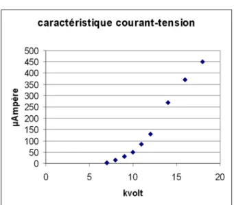
A cold cathode source electron gun (discharge following the Paschen law) provided by OPEA (France) has been chosen for its simplicity and its ability to produce a stable electron beam (intensity-current fluctuations < 1%). The characteristic current-tension relationship of our electron beam, at an Ar pressure of 40 10-3 mbar, is shown in Figure 1. Note however that the flux of electrons activating CL emission on the sample represents less than 10% of the discharge current.
(2) Mechanical mount.
The mount consists of an aluminium chamber connected to a turbomolecular pump. Three angles of incidence are possible: 30°, 45°, 60°.
- it includes the membrane carrier, which acts as an interface between the electron gun and the sample carrier
- it allows microscopic observation of CL
- its large volume allows observation of both standard petrographic thin-sections and pluricentimetric raw rock samples
- it allows pressurization of the sample chamber, so as to observe CL at a CO2 static pressure of several tens of bar.
(3) The membranes and its mount.
This is the critical part under study. The membrane carrier fixes the membrane along the beam path, It must be impervious in a pressure gradient of a few tens of mbar. It must exert minimal mechanical constraints on the membrane and must allow its easy replacement.
The nature of the membrane, namely its density and its constitutive atoms (the lighter, the best), controls the interaction with electrons. Two types of membranes have been tested: - Commercial polycarbonate membranes in use for electron microscopy. They are very easy to mount and un-mount. The one we tested consists of a 100 nm-thick film deposited on a 300µm-mesh Ni grid, to reinforce its resistance to pressure. It is pressed against a rubber o-ring gasket that allows a differential pressure gradient of 1 bar to be sustained.
- 30 to 100nm-thick Si3N4 windows. They are made of 250 µm-thick, 5mm-wide, silicon nitride square films that have been thinned to the desired thickness on a 1,5 mm-wide square area at their center. The membrane is pressed on a rubber o-ring via a steel spring in order to ensure airtightness.
The membrane-to-sample distance is currently of 50 mm, comparable to that of most commercial cold CL devices.
(4) The optical device.
It consists of an Olympus SZ 60 stereozoom with a 6 x zoom lens. It is equipped with a JVC KY-F75U tri-CCD digital camera. The 3 sensors, 12 mm in size, have a resolution of 1360x1024 pixels (1,4 106 pixels, pixel size 7 µm) The characteristic features of images acquired with the stereozoom and the camera are given in Table 1. A Zeiss MM1 spectrometer using a fiber optic coupling is either mechanically mounted on the sample chamber or attached on the stereozoom ocular. It operates in the 0.3–1 mm range with a 3.3 nm spectral resolution.
RESULTS
I MEMBRANE BEHAVIOUR
Commercial polycarbonate membranes.
As soon as the membrane was irradiated, its color changed and the membrane became brittle. In particular, it broke in response to any constraint relaxation due to pressure drop (Plate 1, Fig.1). This kind of membrane therefore, of unique use, is inappropriate to our experimental objectives.
Si3N4 membranes (Plate1, Fig.2)
Mechanical constraints are clearly the limiting-factor for the longevity of Si3N4 membranes, whether they arise from mounting or un-mounting the window, or result from pressure blows. Provided attention is paid to these two critical steps of the experiments (particularly one must ensure smooth pressure variations), longevity of Si3N4 membranes is satisfactory at the scale of laboratory experiments. It is however clearly insufficient for long duration space experiments. The steel spring ensuring airtightness has to be replaced, as it generates excessive constraints on the silicon nitride film. In the following, experiments involving Si3N4 membranes only will be considered.
IIELECTRON BEAM PROPERTIES.
Beam energy loss.
The energy loss due to the intercalation of the membrane on the beam path was calculated using the ESTAR program provided by the National Institute of Standards and Technology. The results, calculated for two membrane thicknesses of 50 and 100 nm, are shown in Table 2. The energy lost by an electron beam along a 50 mm-long path in pressurized CO2 at 10 and 20 mbar has also been considered. The results are shown in Table 3. The predictions show that, for a given beam energy, the energy loss is roughly increased by a factor 2 when the Si3N4 membrane thickness or the CO2 pressure is doubled. Besides, for a given media, the beam energy loss decreases as the beam energy increases. Clearly, the energy loss through the 50 or 100nm-thick Si3N4 membranes appears negligible for beam energies higher than 15keV. Therefore, when the sample is kept under vacuum, the addition of a membrane on the electron gun does not significantly modify the conditions of CL emission. By contrast, the energy loss along a 50mm-long path in CO2 pressurized at 10 and 20 mbar appears critical as it ranges from 10% to 38%, depending on beam energy. Clearly, the optimization of our experimental set-up for the purpose of CL imagery on Mars will necessarily require a minimization of the membrane-to-sample distance.
Angular diffusion of the electron beam.
A preliminary experiment has been performed in order to evaluate the impact of a membrane or of atmospheric CO2 on angular diffusion of the electron beam. The
electron gun being inclined at 60° relative to the normal of the surface sample and the membrane-to-sample distance being fixed at 50mm, the spot has been visualized on strongly CL emitting powdered ZnS. Its diameter has been estimated at 3-4 mm in the sample chamber at 0 mbar CO2 pressure. The beam size increased to >20 mm when a 20 mbar CO2 pressure was maintained in the chamber, with all other conditions being equal. This preliminary experiment points to the fact that angular diffusion will have to be controlled in the future, either actively using an electro-magnetic device or passively within the framework of a new set up with optimized geometry constraints. A larger atmospheric pressure in the chamber or a larger incidence angle of the beam would still enhance angular diffusion.
IIICL IMAGERY AND SPECTROSCOPY
In order to test the effects of putting a membrane at the electron gun exit and/or a CO2 pressure in the sample chamber on CL images, a thin section of basaltic volcanic breccia originating from the Puy de la Vache volcano (Chaîne des Puys, France) has been chosen. The thin section displays 500µm-sized pyroxenes and brecciated plagioclase phenocrysts in a glassy matrix, minor olivine plus accessory minerals.
1. Reference CL image and spectrum. Plate 1, Figure 3 shows a conventional CL
image of the volcanic breccia (no membrane, chamber under vacuum). In order to increase the beam energy at a constant current value, the discharge has been obtained with an Ar pressure less than the commonly used value of ≈ 40 103 mbar (see Figure 1). The discharge current obtained in these conditions is 80 µA. Optimisation of the coupling electron source- sample will be a key point to consider in the context of a space applications where the power supply has to be reduced to a minimum. Plate 1, Figure 3 illustrates the capability of CL to enhance the petrologic features of a basaltic breccia. Two types of phenocrysts, 200 to 500 µm-thick, are easily discriminated by their specific color: fresh plagioclase luminesces in blue to beige whereas altered plagioclase luminesces in yellow. Both phenocrysts are fractured and passively penetrated by the dark glassy matrix along cracks with sharp edges. Fresh plagioclases are corroded by the glass at their periphery whereas altered plagioclase rims luminesce in green. A 110 x 60 µm-wide apatite crystal shows a bright orange CL color. The contour of a 270 µm-long lath of phyllosilicate is underlined by a green CL color. Finally, CL allows 50-100 µm-wide glass beads to be individualized in the matrix, limited by 10µm-large brown CL rims.
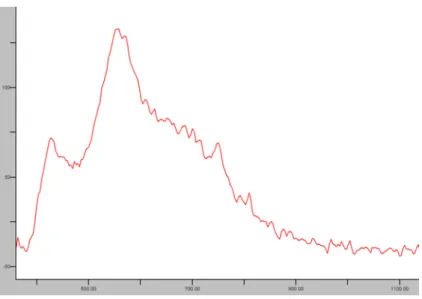
A CL spectrum corresponding to the field imaged is shown in Figure 2. It displays three main bands. The band centered at 550 nm originates from the Mn2+ activator, the band centered at 420 nm probably originates from Eu2+ in plagioclase, the shoulder around 650-700 nm corresponds to Fe3+.
2. CL and spectral degradation due to the membrane. The decrease in luminance
induced by a 50 nm-thick membrane appears obvious on Plate 1, Figure 4. However, the two types of phenocrysts (altered and unaltered plagioclases) and their brecciated texture are still visible and the green luminescent rim around altered plagioclase is observed. The bright orange-luminescent accessory mineral can also be seen.. Only the phyllosilicate lath does not appear any more in the matrix and the glass beads are no
more visible either. Probably, longer exposure times or more sensitive CCD could have compensated for the loss of luminance due to addition of the membrane, but this could not be tested with our present acquisition program. The spectrum obtained with the membrane contains essentially the same spectral information as the spectrum acquired without a membrane, only the emission intensity is decreased by 30%.
3. CL and spectral degradation due to the membrane plus a CO2 atmospheric path. Plate 1, Figures 6 and 7 shows two CL images of a brecciated plagioclase in a basaltic nodule from Puy de la Vache volcano (Chaîne des Puys, France), both acquired with a 50 nm Si3N4 membrane, and with 0 and 20 mbar atmospheric CO2 pressure, respectively. One observes that a drastic decrease in luminescence is induced by the path in pressurized CO2. Note however that the brecciated texture of the plagioclase is still visible. The energy lost by electrons along a 50 mm-long path in CO2 pressurized at 20 mbar was shown previously to amount to ≈ 2.20 keV only (see Table 3). In the case of the experiments shown in Plate 1, Figures 6 and 7, the energy loss along the atmospheric CO2 path was partly compensated by increasing the beam energy from 20 to 22 kV. This experiment reinforces the need for a minimization of the membrane-to-sample distance in a CL device designed for the Mars environment. The CL spectrum obtained from the field imaged on Figure 2, corresponding to a beam path in a 20 mbar CO2 atmosphere, preserves the same spectral information as that obtained in a 0 mbar CO2 atmosphere. The noise is increased as a result of the decrease in luminescence intensity. Note that the possible contribution of a CO2 fluorescence is undetected.
4. Unpolished surface sample. Plate 1, Figure 5 shows the CL image of the raw,
broken (unsawn, unpolished) surface of a piece of basaltic nodule from the Puy de la Vache volcano, at a controlled, martian-like, CO2 pressure of 10 mbar (membrane thickness: 100nm). The rock sample can be only imaged at small magnification, because of the sample roughness. The field imaged in Plate 1, Figure 5 is therefore 4 times larger than the one in Plate 1, Figure 4. This is the reason why the luminance appears to be a less critical parameter in the case of the rock sample CL image. The brecciated plagioclase phenocrysts are still visible by their yellow and pink color, respectively. The dark brown CL-emitting mineral is clinopyroxene. The spatial resolution is however too low, for any further structural detail to be visible.
5. Influence of pressurized CO2 on the quality of CL spectra. CL spectra of the polished surface of a synthetic YAG crystal (a REE-enriched Yttrium Aluminum garnet have been acquired at variable CO2 pressures between 0 to 20 mbar (Figure 5). Figure 5 shows that the spectral information remains essentially the same, whatever the CO2 pressure. Only the noise increases with increasing CO2 pressure, as well as does absorption (see lowered peak maxima).
CONCLUSION PERSPECTIVE OF SHORT-TERM RESEARCH
The concept of an electron lamp as an aid for the spatial exploration of Mars has been validated. However, the duration of life of the Si3N4 membrane has to be increased, particularly by minimizing the mechanical constraints applied on it. The diffusion and the geometrical interface between the membrane, the sample and the microscope were also identified as the most critical points to optimize in the context of spatial exploration. The following aspects should be studied:
- systematic experiments on the angular diffusion taking into account the membrane, the pressure of CO2, the angle of incidence of the electron beam, and the geometry of the interface. The surface of a YAG crystal, whose CL emission is homogeneous and intense, will make it possible to easily visualise the surface irradiated by the electron beam.
- in parallel, theoretical considerations and numerical simulations will be carried out on an electrostatic (or electromagnetic) device with the objective of minimising the consequences of the electron diffusion in a CO2 martian-like atmosphere.
Finally, a 10-20 keV electron beam does not induce any fluorescence in CO2 pressurized at 10 to 20 mbar.
References
Bandfield, J.L., Hamilton, V.E., Christensen, P.R., McSween Jr., H.Y., (2004) Identification of quartzofeldspathic materials on Mars. J. Geophys. Res. 109 (E10009).
Barbin V. (2000) Cathodoluminescence of carbonates shells: biochemical vs diagenetic process. In Pagel M., Barbin V., Blanc Ph. & Ohnenstetter (eds), Cathodoluminescence in Geosciences, Springer Verlag, Chap. 12, p.303-329.
Barbin V. and Schvoerer M. (1997) Cathodoluminescence et géosciences. « Point sur : » C. R. Acad. Sci. Paris., Sciences de la Terre et des Planètes, 325, p. 157-169.
Barbin V, Ramseyer K and Elfman M (2008) Biologic record of added manganese in seawater: a new efficient tool to mark in vivo growth lines in oyster species Crassostrea gigas. International Journal of Earth Sciences (Geol Rundsch) 97:193-199.
Barbin V., Blanc Ph., Klossa B., Lorin Cl. and Thomas R. (1999) Cathodoluminescence : a new approach to the in situ study of martian surface mineralogy. Symposium International : Programme d’exploration de Mars & missions de retour d’échantillons (Paris)., Résumé CNES. Edit.
Barker C.E. and Kopp O.C. (1991) Luminescence microscopy and spectroscopy: qualitative and quantitative applications, SEPM Short Course 25 (Tulsa, OK, 194 pp.).
Baumer, A., Blanc, Ph., Cesbron, F., Ohnenstetter, D. (1997) Cathodoluminescence of synthetic (doped with rare-earth) and natural anhydrites. Chemical Geology 138, 73-80.
Blanc Ph., Thomas R., Klossa B., Lorin C. and Barbin V. (1999) Designing a cathodoluminescence equipment for mars exploration. Symposium International : Programme d’exploration de Mars & missions de retour d’échantillons (Paris)., Résumé CNES. Edit. Boggs S. and Krinsley D. (2006) Application of Cathodoluminescence Imaging to the Study of Sedimentary Rocks. Cambridge University press, 165p.
Chevrier, V. and Mathé P.E. (2007) Mineralogy and evolution of the surface of Mars: A review. Planerary and Space Science 55, pp. 289-314.
Denson J., Ivey D.M. Sears D.W.G, Gucsikand A. ,Vidéki R.and Keck W.M (2007)
Cathodoluminescence and its application for biosignature analysis of Mn-containing biogenic minerals: a review Lunar and Planetary Science 38, 1009
Chevrier V. and Mathe, P.E.(2007) Mineralogy and evolution of the surface of Mars: A review. Planetary and Space Science 55, 289–314.
Garcia D., Pascal M.L., Roux J. (1996) Hydrothermal replacement of feldspars in igneous enclaves of the Velay granite and the genesis of myrmekites. European Journal of Mineralogy, 8 p. 703-717.
Ginibre C., Wörner G., Kronz, A. (2004) Structure and dynamics of the Laacher See magma chamber (Eifel, Germany) from major and trace element zoning in sanidine: A cathodoluminescence and electron microprobe study. Journal of Petrology, 45, 2197-2223. Gledhill, J. A. (1973) The range-energy relation for 0.1-600 keV electrons. J. Phys. A: Math. Nucl. Gen. 6, 1420-1428
Gucsik A., Nishido H., Ninagawa K., Okumura, T , Wilcox J.Z., Urguiles E., Götze J.,. Bérczi S., Kereszturi Á. Hargitai, H., Polgári M. and Nagy S., (2006) Cathodoluminescence and its applications in the planetary sciences: a review. Lunar and Planetary Science 37.
Kershaw S. (1994) Cathodoluminescence of Silurian stromatoporoids from Gotland, Sweden. Cour. Forsch. Inst. Senckenberg, 172: 307-318, Frankfurt am Main.
McSween, H.Y Jr. (1994) What we have learned about Mars from SNC meteorites. Meteoritics 29, pp. 757–779.
Marshall, D.J. (1988) Cathodoluminescence of geological materials. Unwin-Hyman, Boston, Mass.
Melezhik V. A., Fallick A. E, Medvedev P.V. and Makarikhin V. V. (1999) Extreme 13Ccarb enrichment in ca. 2.0 Ga magnesite–stromatolite–dolomite–‘red beds’ association in a global context: a case for the world-wide signal enhanced by a local environment. Earth-Science Reviews, v. 48, Issues 1-2, Pages 71-120.
Michard, A. (1989) Rare earth systematics in hydrothermal fluids. Geochim. Cosmochim. Acta 53, 745-750
Owen M. R.and Anders M. H. (1988)Evidence from cathodoluminescence for non-volcanic origin of shocked quartz at the Cretaceous/Tertiary boundary. Nature 334, 145 - 147
Pagel M., Barbin V., Blanc Ph. and Ohnenstetter (2000) Cathodoluminescence in Geosciences : an overview and perspectives. In Pagel M., Barbin V., Blanc Ph. & Ohnenstetter (eds), Cathodoluminescence in Geosciences, Springer Verlag, Chap.1, p.1-21.
Panczer G.,Ollierb N., Champagnon B., Gaft M., Boudeulle M., Moine B. (2003) New development in time-resolved micro-photoluminescence spectroscopy of heterogeneous natural and synthetic inorganic materials. Optical Journal 23, 253-257
Poitrasson F., Hanchar J. M., Schaltegger U. (2002) The current state and future of accessory mineral research. Chem.l Geol.191, 3-24.
Poulet, F., Bibring, J.-P., Mustard, J.F., Gendrin, A., Mangold, N., Langevin, Y., Arvidson, R.E., Gondet, B., Gomez, C., the OMEGATeam, (2005) Phyllosilicates on Mars and implications for the early Mars history. Nature 481, 623–627.
Ramseyer K., Boles J.C. and Lichtner P.C. (1992) Mechanism of plagioclase albitization. Journal of Sedimentary Petrology, 62, 349-356.
Ramseyer K and Mullis J. (2000) Geological application of cathodoluminescence of silicates in Pagel M., Barbin V., Blanc Ph. & Ohnenstetter (eds), Cathodoluminescence in Geosciences, Springer Verlag, Chap. 7, p.177-192.
Schärer, U., de Parseval, P., Polvé, M., de Saint Blanquat, M. (1999) Formation of the Trimouns talc-chlorite deposit (Pyrenees) from persistent hydrothermal activity between 112 and 97 Ma. Terra Nova, 11, 30-37.
Smith P. H., Bell J. F III, Bridges, Britt D. T., Gaddis L.,Greeley R., Keller H. U., Herkenhoff K. E., Jaumann R.,Johnson J. R., Kirk R. L., Lemmon J. , Maki J. N., Malin M. C., Murchie S. L., Oberst, Parker T. J., Reid R. J., Sablotny R., Soderblom L. A., Stoker C., Sullivan R., Thomas N.,Tomasko M. G., Ward W., Wegryn E. (1997) Results from the Mars Pathfinder Camera. Science 278, 1758-1764.
Smith D.E., Zuber M. T., Solomon S. C., Phillips R. J., Head J. W., Garvin J. B., Banerdt W. B., Muhleman D. O., Pettengill G. H., Neumann G. A., Lemoine F. G., Abshire J. B., Aharonson O., Brown C. D., Hauck S. A., Ivanov A. B., McGovern P. J., Zwally H J., Duxbury T. C., (1999) The global topography of Mars and implications for surface evolution, Science, 284, 1495-1503.
Steele I. M., Smith J. V., Skirius C. (1985). Cathodoluminescence zoning and minor elements in forsterites from the Murchison (C2) and Allende (C3V) carbonaceous chondrites . Nature, 313, no6000, pp. 294-297
Thomas R., Gille P. and Barbin V. (2002) Detection of past biological activity in martian sediments under cathodoluminescence. Word-File for ESA-SP Exo/Astrobiology meeting in Graz. European Space Agency, (Special Publication) ESA SP, Issue 518, pp.563-564.
Thomas R., Barbin V., Gille P., Léveillé R., MacGibbon J., Miko L., Ramboz C. and Westall F (2005) 5th Canadian Space Exploration Workshop, Longueuil, Quebec. "Cathodoluminescence instrumentation for planetary probes”.
Westall F., Brack A., Hofmann B., Horneck G., Kurat G., Maxwell J., Ori G.G., Pillinger C., Raulin F., Thomas N., Fitton B., Clancy P. (2000) An ESA study for the search for life on Mars. Planetary and Space Science, 48: 181-202.
Acknowledgments
This paper received financial support from CNES (R et T Lampe à électrons, analyse de sédiments martiens par cathodoluminescence’ 2003). The authors are grateful to F. Westall, E. Vergès, L. Perdereau and X. Drothiere for their technical help and support.
1
2
3 4
5
Magnification X 1 X 6 Size of the imaged field (mm2
x mm) 10 x 7 1.6 x 1
Pixel size in the object plane (µm) 7 1.2
Table 1: Characteristic features of images acquired with our optical setup a JVC KYF75U tri-CCD digital camera and with an Olympus SZ60 stereozoom
Membrane thickness (nm) 50 100
Beam energy (keV) 10 15 20 10 15 20 Energy loss (eV) 284 (2.8) 210 (1.4) 169 (0.9) 569 (5.7) 419 (2.8) 338 (1.7)
Table 2: Energy lost by an electron beam passing through a 50 or 100nm-thick Si3N4 membrane.
CO2 pressure (mbar) 10 20
Beam energy (keV) 10 15 20 10 15 20 Energy loss (eV) 1920 (19) 1410 (9.4) 1130 (5.7) 3810 (38) 2790 (19) 2230 (11)
Table 3: Energy lost by an electron beam along a 50mm- path in pressurized CO2. Numbers between are energy losses in %.
Fig.1: Tension-current relationship of an OPEA cathodyne cold cathode instrument at an Ar pressure of 40 10-3 mbar
Fig. 2: CL spectral response corresponding to an area of ≈ 2.5 x 2 mm. The conditions are 17 keV, 80 µA, Ar pressure of < 40 10-3 mbar and 0 mbar CO2 pressure as used for Fig. 3 on Plate 1
Fig. 3: CL spectral response corresponding to an area of ≈ 2.5 x 2 mm through a 50 nm-thick Si3N4 window. The conditions are 17 keV, 80 µA, Ar pressure of 40 10-3 mbar and 0 mbar CO2 pressure as used for Fig. 4 on Plate 1
Fig. 4: CL spectral response corresponding to an area of ≈ 2.5 x 2 mm through a 50 nm-thick Si3N4 window at a distance of 50 mm. The conditions are 22 keV, 220 µA, and 20 mbar CO2 pressure as used for Fig. 6 on Plate 1
Fig. 5: CL spectra of the polished surface of a synthetic YAG crystal acquired at CO2 pressures between 0 to 20 mbar.
PLATE 1
Plate 1, Fig. 1: Microphotograph of the Polycarbonate membrane window on a Ni grid after rupture. The size of an individual membrane is 400 x 400 µm.
Plate 1, Fig. 2: Microphotograph of the Si3N4 membrane window after rupture. The window is 1.5 x 1.5 mm in size.
Plate 1, Fig. 3: CL image of a basaltic breccia (Puy de la Vache, Chaîne des Puys, France). Beam conditions: 17 kV, 80 µA, Ar pressure < 40 10-3 mbar. Size of the imaged field: 2.5 x 2 mm. Exposure duration: 4s. (raw image without any treatment).
Plate 1, Fig. 4: CL image of a basaltic breccia with a 50 nm-thick Si3N4 window placed at the electron gun exit (Puy de la Vache, Chaîne des Puys, France). Beam conditions: Ar pressure of 40 10-3 mbar, 17 kV, 80 µA. 0 CO2 pressure in the chamber. Size of the imaged field: 2.5 x 2 mm. Exposure duration: 4s.
Plate 1, Fig. 5: CL image of the raw (unsawn, unpolished) surface of a piece of basaltic nodule from the Puy de la Vache volcano, at a controlled, martian-like, CO2 pressurize of 10 mbar (membrane thickness: 100nm). Beam conditions: 17 kV, 120 µA. Size of the imaged field: 10 x 8 mm. Exposure duration time: 4s.
Plate 1, Fig. 6: Effect of a CO2 pressure on the CL image of a brecciated plagioclase (Puy de la Vache volcano, Chaîne des Puys, France). For both microphotographs, a 50 nm-thick Si3N4 window is placed at the electron gun exit and the beam path length is 50 mm. Beam path in an Ar pressure of 40 10-3 mbar, 0 mbar CO2 pressure, beam conditions: 20 kV, 110 µA. Size of the imaged field: 2.5 x 2 mm.
Plate 1, Fig. 7: Effect of a CO2 pressure on the CL image of a brecciated plagioclase (Puy de la Vache volcano, Chaîne des Puys, France). For both microphotographs, a 50 nm-thick Si3N4 window is placed at the electron gun exit and the beam path length is 50 mm. Beam path in 20 mbar CO2 pressure, beam conditions : 22 kV, 220 µA. Size of the imaged field : 2.5 x 2 mm. Exposure duration time: 4s.