Publisher’s version / Version de l'éditeur:
Vous avez des questions? Nous pouvons vous aider. Pour communiquer directement avec un auteur, consultez la Questions? Contact the NRC Publications Archive team at
[email protected]. If you wish to email the authors directly, please see the first page of the publication for their contact information.
https://publications-cnrc.canada.ca/fra/droits
L’accès à ce site Web et l’utilisation de son contenu sont assujettis aux conditions présentées dans le site LISEZ CES CONDITIONS ATTENTIVEMENT AVANT D’UTILISER CE SITE WEB.
Student Report (National Research Council of Canada. Institute for Ocean Technology); no. SR-2005-23, 2005
READ THESE TERMS AND CONDITIONS CAREFULLY BEFORE USING THIS WEBSITE.
https://nrc-publications.canada.ca/eng/copyright
NRC Publications Archive Record / Notice des Archives des publications du CNRC :
https://nrc-publications.canada.ca/eng/view/object/?id=97555e26-baaa-489e-ad62-df1d9a8f1cd5 https://publications-cnrc.canada.ca/fra/voir/objet/?id=97555e26-baaa-489e-ad62-df1d9a8f1cd5
NRC Publications Archive
Archives des publications du CNRC
For the publisher’s version, please access the DOI link below./ Pour consulter la version de l’éditeur, utilisez le lien DOI ci-dessous.
https://doi.org/10.4224/8894901
Access and use of this website and the material on it are subject to the Terms and Conditions set forth at
Design of the IOT wave suppressor
DOCUMENTATION PAGE
REPORT NUMBER SR-2005-23
NRC REPORT NUMBER DATE
December 2005 REPORT SECURITY CLASSIFICATION
Unclassified
DISTRIBUTION Unlimited TITLE
Design of The IOT Wave Suppressor
AUTHOR(S)
Jeswin Jeyasurya
CORPORATE AUTHOR(S)/PERFORMING AGENCY(S)
Institute for Ocean Technology, National Research Council, St. John’s, NL PUBLICATION
N\A
SPONSORING AGENCY(S) IOT
IOT PROJECT NUMBER 42_2104_16 NRC FILE NUMBER KEY WORDS Wave Suppressor, CPF PAGES iii,14, App. A,B FIGS. 9 TABLES SUMMARY
The Institute for Ocean Technology specializes in researching and testing models of ships. The Department of National Defence has contracted IOT to develop a stern appendage that will reduce hydrodynamic resistance on the Halifax Class frigate. This appendage will also improve speed and propeller cavitation performance, and reduce the stern wave. The model used for testing contains sensitive electrical equipment which is vulnerable to forces induced by the stern wave impacting the model at the end of high-speed runs. There is also a risk of the stern wave washing over the transom and causing further damage to equipment. Researchers at the Institute have proposed a method to solve these problems through the development of a device called the Wave
Suppressor. This device would be used to dissipate the wave energy, and thereby reduce the impact force of the wave on the stern of the model and prevent the stern wave from washing over the transom.
This report details the design considerations used in the development of the proposed mechanism and describes its various components. It covers the design criteria that the Wave Suppressor must meet, and how the Wave Suppressor fulfills these requirements. The report first sets the design criteria and then proceeds to describe the Suppressor’s connection to the tow tank carriage, the design factors involved in ensuring the wave will be fully suppressed, and the control of the suppressor. It also includes calculations that were used in the design process and provides assembly drawings of the wave suppressor.
ADDRESS National Research Council Institute for Ocean Technology Arctic Avenue, P. O. Box 12093 St. John's, NL A1B 3T5
National Research Council Conseil national de recherches Canada Canada Institute for Ocean Institut des technologies
Technology océaniques
DESIGN OF THE IOT WAVE SUPPRESSOR
SR-2005-23
Jeswin Jeyasurya
SUMMARY
The Institute for Ocean Technology specializes in researching and testing models of
ships. The Department of National Defence has contracted IOT to develop a stern
appendage that will reduce hydrodynamic resistance on the Halifax Class frigate. This
appendage will also improve speed and propeller cavitation performance, and reduce the
stern wave. The model used for testing contains sensitive electrical equipment which is
vulnerable to forces induced by the stern wave impacting the model at the end of
high-speed runs. There is also a risk of the stern wave washing over the transom and causing
further damage to equipment. Researchers at the Institute have proposed a method to
solve these problems through the development of a device called the Wave Suppressor.
This device would be used to dissipate the wave energy, and thereby reduce the impact
force of the wave on the stern of the model and prevent the stern wave from washing over
the transom.
This report details the design considerations used in the development of the proposed
mechanism and describes its various components. It covers the design criteria that the
Wave Suppressor must meet, and how the Wave Suppressor fulfills these requirements.
The report first sets the design criteria and then proceeds to describe the Suppressor’s
connection to the tow tank carriage, the design factors involved in ensuring the wave will
be fully suppressed, and the control of the suppressor. It also includes calculations that
TABLE OF CONTENTS
1.0 INTRODUCTION……….1 2.0 FACILITY DESCRIPTION………..2 3.0 SUPPRESSOR COMPONENTS………..4 4.0 DESIGN CRITERIA……….4 5.0 SUPPRESSOR DESIGN………...5 5.1 Design overview………55.2 Suppressor and Carriage Interface……….6
5.2.1 Location, Compatibility, and Attachment………6
5.2.2 Pull Point Compatibility………..7
5.3 Wave Suppression Design Factors………9
5.3.1 Hinge Design………...9
5.3.2 Frame Design……….10
5.4 Suppressor Control………...11
5.4.1 Suppressor Deployment……….11
5.4.2 Suppressor Stopping………..12
6.0 SUPPRESSOR AS-BUILT MODIFICATIONS……….13
7.0 REFERENCES………14
APPENDIX A: Design Calculations
TABLE OF FIGURES
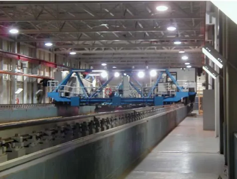
Figure 1. Tow Tank and Carriage………2
Figure 2: Illustration of Model and Carriage with raised Wave Suppressor…....…...…3
Figure 3: Illustration of Model and Carriage with lowered Wave Suppressor………....…3
Figure 4. Illustration of Wave Suppressor ………..6
Figure 5. Illustration of Suppressor and Carriage interface ………7
Figure 6. Illustration of mounted Suppressor with Pull Point Apparatus in place………..8
Figure 7. Illustration of Suppressor Cross-section ………11
Figure 8. Illustration of deployed Wave Suppressor with chains……….….12
Figure 9. Picture of Installed Suppressor and Model Stern………...…13
1.0 INTRODUCTION
The Institute for Ocean Technology - National Research Council has been contracted by
the Department of National Defence to carry out research in the development of a stern
appendage for the Halifax Class frigate. This research has been driven by a concern
regarding escalating fuel prices. Once it is developed, the stern appendage will reduce
hydrodynamic resistance on the vessel, which will increase the fuel efficiency and reduce
operating costs. The institute will perform tests in the towing tank facility to determine
which stern flap arrangement will provide the least amount of hydrodynamic resistance.
At the end of high velocity runs (maximum test speed is 4.4 m/s), the wave following the
model will slam into its stern with a large amount of force. This force can cause damage
to sensitive electrical equipment. There is also a possibility that the stern wave will wash
over the transom and cause further damage to equipment. In order to solve these
problems, a device has been developed to dissipate the energy of the wave before it
reaches the stern of the model. This device, called the Wave Suppressor, is a hinged
two-piece frame with expanded metal mesh on the bottom half. Near the end of each
high-speed run, the suppressor is manually deployed into the water with the expanded metal on
the bottom half dissipating the energy of the wave before it reaches the stern. This report
2.0 FACILITY DESCRIPTION
The testing facility for the Halifax Class frigate is the IOT Clearwater Towing Tank. The
vessel will be attached to a carriage that will run down the tank at various speeds, up to a
maximum of 4.4 m/s. The experiments will be performed in calm water, without the use
of the wave-making device. The model used for testing is 9 m in length with a flat
transom stern.
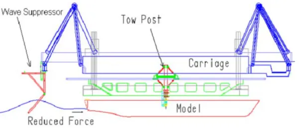
The diagrams below show a side view of the testing configuration. The model is attached
to the carriage using a Tow Post. When the model reaches the end of the run, the
following wave keeps travelling until it hits the stern. The suppressor will reduce the
impact force and ensure that the wave will not wash over the stern.
Figure 2: Illustration of Model and Carriage with raised Wave Suppressor
3.0 SUPPRESSOR COMPONENTS
The wave suppressor consists of the following components:
• Hollow Structural Steel Frame. 2”x 2” and 3”x 2” cross section • Expanded Metal Sheets, 45 Percent Porosity
• Angle Steel, 5”x 3” and 2”x 2” cross section • Fabricated Steel Clamps
• Fabricated Steel Support Bracket • Steel Chain
4.0 DESIGN CRITERIA
The underlying principle of the wave suppressor was to design a steel hinged frame
covered with expanded metal mesh. The frame would be dropped at the end of the run
and held at an angle to dissipate the wave energy before it reached the stern of the model.
In designing this frame, the following design criteria had to be met.
• Suppressor attachment and compatibility
o The suppressor must be able to attach to both the east and west ends of the
carriage.
o The suppressor must be designed to accommodate an existing Pull Point
Apparatus, which will create an obstruction, since it is also centered on the
west end of the carriage.
• Suppressor Design
o The suppressor must have hinges that are able to withstand the force of the
wave.
o The suppressor must be able to dissipate the energy of the stern wave
o The suppressor must be designed to handle a max wave height of 12”
o When the suppressor is fully deployed it must form a 45° angle to the
water surface and the end of the frame should be at a depth of 15.75”.
o The suppressor must be 80” in width.
• The suppressor must be designed for rapid manual deployment.
5.0 SUPPRESSOR DESIGN
5.1 Design Overview
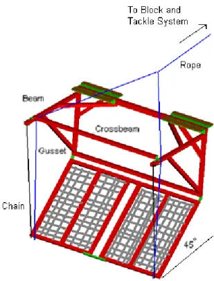
The wave suppressor was designed as a two-piece frame, hinged in the middle. The top
piece will be clamped to the carriage and the bottom piece free to drop into the water.
The frame consists of 2 “x 2” steel box tube with support gussets to prevent bending from
forces that arise when the frame is deployed. There are two beams on either end of the
used to stop the suppressor when it is deployed. Ropes attached to the bottom frame are
used to raise the suppressor. The bottom frame also has multiple layers of expanded
metal sheets bolted onto it.
Figure 4. Illustration of Wave Suppressor
5.2 Suppressor and Carriage Interface
5.2.1 Location, Compatibility, and Attachment
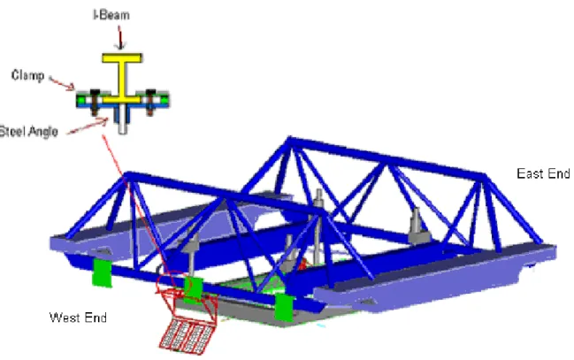
It was determined that the best location for attaching the suppressor to the carriage is to
clamp it to the underside of an I-Beam running beneath the west end of the carriage. A
special clamp has been fabricated to clamp the steel angle on the Suppressor to the
I-Beam. Another I-Beam runs beneath the east end of the carriage, hence this method of
clamp and steel angle together will provide the clamping force when the bolts are
tightened. Calculations were performed to ensure that the clamping force of the bolt is
large enough to hold the suppressor to the carriage without any chance of failure. These
calculations can be seen in Appendix A.
Figure 5. Illustration of Suppressor and Carriage interface
5.2.2 Pull Point Compatibility
The suppressor was designed to avoid interference with the existing pull point apparatus.
The pull point apparatus is 3″ wide at its widest point and extends vertically, centered on
Figure 6. Illustration of mounted Suppressor with Pull Point Apparatus in place
To prevent interference with the Pull Point Apparatus, the bottom half of the suppressor
was designed as a two-piece frame with a 5″ gap in the middle. Because the Pull Point
Apparatus is 3″ wide at its widest point, the five-inch gap will leave an inch of clearance
on either side. This gap is along the whole length of the frame but can be made smaller
by closing the gap using expanded metal sheets. This option will only be utilized if it is
determined that a significant amount of wave energy is passing through the gap. In
addition a support bracket has been fabricated to connect the bottom of the two pieces
together (see figure 6). This will reduce the effects of any twisting moments on the
5.3 Wave Suppression Design Factors
5.3.1 Hinge Design
The hinge was designed to be a simple pin connection connecting the top and bottom
frames together. It was necessary to ensure that the steel bolts used in the hinge will have
enough strength to resist the various shearing forces acting on it. These include forces
caused by the weight of the suppressor, the force of the wave impact, and hydrostatic
pressure forces. The weight of the suppressor was determined by summing the weights
of the individual components. The force of the wave impact was found using the
momentum equation. Ft = mV Where: F = Force (N) t = time (s) m = mass (kg) V = velocity (m/s)
The hydrostatic force was found using the hydrostatic pressure equation
F = PA
Where: F = Force (N) P = Pressure (kPa)
A = Cross-sectional area (m^2)
As a prerequisite to performing these calculations, the maximum height and volume of
the wave over the suppressor had to be determined. Detailed calculations can be found in
5.3.2 Frame Design
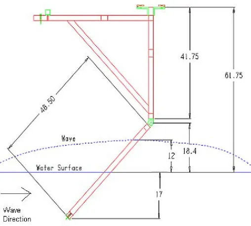
The lengths of both the top and bottom pieces of the frame were determined using two
design requirements. The first requirement was that the suppressor should handle a
maximum wave height of 12″. This means that before it is deployed (bottom frame
parallel to water surface), the suppressor should allow up to a 12” high wave to pass
beneath it. The second requirement was that the depth of the suppressor should be at
least 15.75″ below the water surface when fully deployed (at a 45° angle to water
surface). To satisfy the first requirement, the top piece had a designed length of 41.75″.
Since the I-beam is at a fixed height of 61.75″ above the water, when the suppressor is
attached there will be a gap larger than the minimum 12″ of clearance required, ensuring
there is no wave interference. The bottom piece has a length of 48.5″. This length
satisfies the second design requirement by ensuring that when fully deployed, the
suppressor will have a depth greater than the required 15.75″ below the water surface.
The frame width is 80” as initially specified. This width is sufficient as the model is 37″
in width. Two to four layers of expanded metal mesh will be bolted onto the edge of the
frame, depending on how many layers are needed to adequately dissipate the wave
energy. This will be decided after the Wave Suppressor is tested in the towing tank.
Each layer of expanded metal consists of two 48″ by 37.5″ sheets, as this will leave 5″ of
clearance space for the Pull Point Device. See Figure 7, Illustration of Suppressor
Figure 7. Illustration of Suppressor Cross-section
5.4 Suppressor Control
5.4.1 Suppressor Deployment:
The suppressor was designed to be deployed using a block and tackle system. Ropes will
be connected from the ends of the bottom frame to a block and tackle system on the
carriage. The purpose of this system is to reduce the amount of force required to raise the
suppressor. A jam cleat will be used to hold and release the rope when it is ready to be
5.4.2 Suppressor Stopping
The design criteria of the wave suppressor specified that when fully deployed, it should
be at a 45 degree angle to the water surface. This is so that the wave will ride up the
suppressor rather than directly impact it. To satisfy this criterion, two beams were place
on the top corners of the suppressor that extend out in front of it. Chains have been
attached to each of these beams with the other ends of the chains attaching to the ends of
the bottom frame. The length of the chain has been predetermined so that when the
suppressor is released, it will stop at a 45° angle to the water surface. The metal links in
the chain are strong enough to withstand the impact, and gussets have been placed
underneath each beam to prevent bending from the impact force. In addition a crossbeam
has been added to provide support in the transverse direction (see figure 8).
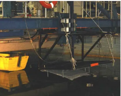
6.0 Suppressor As-Built Modifications
Figure 9. Picture of Installed Suppressor and Model Stern
During the installation of the suppressor a number of small modifications were made to
the original design. A section had to be cut out of the center of the top of the frame,
between the pieces of steel angle. This modification was made to avoid interference with
a gusset on the I-beam that was creating an obstruction. In addition, the chain was
attached to I-bolts on the carriage rather to the ends of the corner beams as originally
planned. This was done so that the carriage rather than the suppressor would absorb the
impact force. The suppressor was too heavy to raise manually so an electric winch was
used to raise it. The suppressor can still be quickly released using the jam cleat. Finally,
to adequately dissipate the wave energy and reduce the force and height of the wave
impacting the model.
7.0 REFERENCES
Shigley, J.E., Mischke, C.R. (1989). Mechanical Engineering Design 5th edition . United
States of America: McGraw-Hill, Inc.
ASME/ANSI B18.3-1986, Socket Cap, Shoulder, and Set Screws (Inch Series). New
APPENDIX A
Design Calculations
Design Calculations
All Calculations were performed in metric except for calculations involving loads on bolts, which are performed in British Standard.
-
Wave Volume over suppressor calculations
General wave profile equation
Z = H/2*sin (kx - wt)
Z & x – wave profile coordinates H – Amplitude of wave
k – wave number w – frequency (radians) t – time
GEDAP Program WAVE (Version 1.20) generated a table of values of wave parameters for 7 m deep water (towing tank is 7 m deep)
Parameters were selected based on which set of values matched closest the following criteria
- Max wave speed is 4.4 m/s - Wave length is greater than 9 m - Max Amplitude (H) is 0.6 m
The set of values that matched closest to the initial criteria include these other values.
w = 2.0942 rad/s k = .22897 m^-1 Period = 3 s
Phase Velocity = 4.6649 m/s Wave Length = 13.995 m
Wave Profile Equation (with values substituted)
Z = 0.3*sin (0.44897x – 2.0942t)
The wave profile and the wave suppresser profile view were graphed in Matlab using the following equations
Z = x
Wave Profile
Z = 0.3*sin (0.44897x – 2.0942t) +0.4
t = 2.35 was substituted into the above equation. Using Matlab it was determined that this was the time at which the maximum amount of water was over the suppressor.
Graph of Wave Profile and Wave suppressor
Integrating in the grey shaded area, it was determined that the area of water over the suppressor was 0.2438 m^2
In addition the graph shows that the length of suppressor underwater is 0.81384 m, and the depth to which it extends is 0.6925 m.
The Mass of water was found using the width of the suppressor (2 m), the calculated area (0.2438 m^2), and the density of water (1000 kg/m^3).
m = Width*Area*Density m = 2*.2438*1000
m = 487.6 kg
Wave Impact Equation:
F = mV/t
M = Mass of wave
V = Phase velocity of wave t = ½ wave period
F = 487.6*4.6649/1.5
The wave impact force is 1516 N
Hydrostatic Pressure Calculations
For these calculations it is assumed that the wave suppressor is a solid plate. This will result in the absolute maximum pressure being calculated
P = density*gravity*height
Density = 1000 kg/m^3 Gravity = 9.8m/s^2 Height = 0.6925/2
The height (distance to center of gravity of plate) is half of the depth to which the wave suppressor extends.
P = 1000*9.8*0.3463 P = 3393.25 Pa
P = F/A F = P*A
A = Area of suppressor under water
F = 3395.25*(2*0.81384) = 5523.2 N
The hydrostatic force is 5523.2 N
Center of Pressure Calculations
Ixx = 1/12*base*length Ixx = 1/12*2*0.81384 Ixx = 0.089839
Yc = Length/2 (center of gravity of plate under water) = 0.81384/2
= 0.40692 m
Yp = Center of pressure of suppressor Yp = Yc + Ixx/ (Area*Yc)
= 0.40692 + 0.089839/(1.62768*0.40692)
Yp = 0.54256 m
Gravitational Force Calculations
Weight of bottom frame.
Expanded Metal, 45 % porosity, 16.5 kg/ layer. 4 Layers, 66 kg
Hollow Structural Steel, 34 kg
Total 100 kg
Gravitational force = 100*9.81 = 981 kg
Using this information, that is the wave impact force, the hydrostatic pressure force, the gravitational force and location of these forces, the forces on the hinges and the stopping chain can be determined.
Hinge and Chain Forces
Known: Fi = 1516 N Fp= 5523.2 N Fg ~1000 N Unknown:
Ft - Tension force on chain
Fhy, Fhz - y and z components of hinge force
∑Fy = 0
∑Fz = 0
2Fhz – Fg – Fp*sin(45) + 2*Ft*cos(8.7) = 0 (2)
∑Mx = 0
-(2*Ft*cos(8.7))*0.88 – (2*Ft*sin(8.7))*0.88 +Fg*cos(45)*0.625
+ Fi*0.575 + Fp*0.813 = 0 (3)
Ft = 2901 N
Substitute in to Equation (1) and (2)
Fhy = -3013 N
Fhz = -416 N
Total hinge force = Sqrt(Fhy^2 +Fhz^2)
Fh = 3041N Fh = 684 lb
Minimum tensile strength - 7/16” coarse thread bolt = 19 100 lb (ASME/ANSI B18.3-1986, p. 146)
Max shear load on bolt is 0.4*min tensile strength (Shigley, Mischke, 1989, p.12)
For 7/16” bolt, max shear = 19100* 0.4 = 7640 lb
Shear force on hinge bolt = 684 lb << 7640 lb
Vertical Clamping Force Calculations
Forces on half of the frame
Fc = clamping force of bolt
Ftz = Ft*cos(8.7) = 2901*cos(8.7) = 2867.6 N Fty = Ft*sin(8.7) = 2901*sin(8.7) = 438.8 N
Fhz = 416 N Fhy = 3013 N Fg1 = (3.77kg)*9.81 = 37 N Fg2 = (7.65kg)*9.81 = 75 N Fg3 = (7.14kg)*9.81 = 70 N Fg4 = (11.72 kg)*9.81 = 115 N Fg5 = (11.72 kg)*9.81 = 115 N ∑Mx = 0 Fc*9 = Ftz*52 + Fty*3 + Fg1*48.5 + Fg2*30 + Fg3*23 + Fg4*4.5 + Fg5*4.5 + Fhy*43.25 – Fhz*4.5
Fc = 31595 N Fc = 7102.8 lb
The clamping force of the bolts must be greater than 7102.8 lb. This force is distributed over three bolts.
Clamping force (force) required per bolt:
7102.8/3 = 2367.6 lb
This force can also be seen as the tensile load on the bolt
Max tensile load on bolt is the proof load
½” bolt proof load = 19800 lb (ASME/ANSI B18.3-1986, p. 146)
2367.6 lb << 19800 lb