HAL Id: hal-02909553
https://hal.archives-ouvertes.fr/hal-02909553
Submitted on 30 Jul 2020HAL is a multi-disciplinary open access archive for the deposit and dissemination of sci-entific research documents, whether they are pub-lished or not. The documents may come from teaching and research institutions in France or abroad, or from public or private research centers.
L’archive ouverte pluridisciplinaire HAL, est destinée au dépôt et à la diffusion de documents scientifiques de niveau recherche, publiés ou non, émanant des établissements d’enseignement et de recherche français ou étrangers, des laboratoires publics ou privés.
Electric and antiferromagnetic chiral textures at
multiferroic domain walls
J.-Y. Chauleau, T. Chirac, S. Fusil, Vincent Garcia, W. Akhtar, J. Tranchida,
P. Thibaudeau, I. Gross, C. Blouzon, A. Finco, et al.
To cite this version:
J.-Y. Chauleau, T. Chirac, S. Fusil, Vincent Garcia, W. Akhtar, et al.. Electric and antiferromagnetic chiral textures at multiferroic domain walls. Nature Materials, Nature Publishing Group, 2020, 19, pp.386-390. �10.1038/s41563-019-0516-z�. �hal-02909553�
1
Electric and antiferromagnetic chiral textures at multiferroic domain walls
12
J.-Y. Chauleau1,2, T. Chirac1, S. Fusil3,8, V. Garcia3, W. Akhtar4, J. Tranchida5§, P. Thibaudeau5, I. Gross4, 3
C. Blouzon1, A. Finco4, M. Bibes3, B. Dkhil6, D.D. Khalyavin7, P. Manuel7, V. Jacques4, N. Jaouen2, M. 4
Viret1* 5
6
1SPEC, CEA, CNRS, Université Paris-Saclay, 91191 Gif-sur-Yvette, France.
7
2Synchrotron SOLEIL, 91192 Gif-sur-Yvette, France
8
3Unité Mixte de Physique, CNRS, Thales, Univ. Paris-Sud, Université Paris-Saclay, 91767 Palaiseau,
9
France
10
4Laboratoire Charles Coulomb, Université de Montpellier and CNRS, 34095 Montpellier, France
11
5CEA – DAM le Ripault, BP 16, 37260 Monts, France
12
6Laboratoire Structures, Propriétés et Modélisation des Solides, CentraleSupélec, Université Paris
13
Saclay, CNRS UMR8580, F-91190 Gif-Sur-Yvette, France
14
7ISIS Facility, STFC, Rutherford Appleton Laboratory, Didcot OX11 0QX, UK
15
8 Université d’Evry, Université Paris-Saclay, Evry, France
16 17
§ : now at ‘Multiscale Science Department, Sandia National Laboratories, P.O. Box 5800, MS1322, 87185
18
Albuquerque, NM, United States’
19 20
* e-mail: michel.viret@cea.fr
21
Chirality, a foundational concept throughout science, may arise at ferromagnetic domain walls1
22
and in related objects such as skyrmions2. However, chiral textures should also exist in other types
23
of ferroics such as antiferromagnets for which theory predicts that they should move faster for
24
lower power3, and ferroelectrics where they should be extremely small and possess unusual
25
topologies4,5. Here we report the concomitant observation of antiferromagnetic and electric chiral
26
textures at domain walls in the room-temperature ferroelectric antiferromagnet BiFeO3.
27
Combining reciprocal and real-space characterization techniques, we reveal the presence of
28
periodic chiral antiferromagnetic objects along the domain walls as well as a priori energetically
29
unfavorable chiral ferroelectric domain walls. We discuss the mechanisms underlying their
30
formation and their relevance for electrically controlled topological oxide electronics and
31
spintronics.
32 33
Metallic ferromagnets have been the elemental bricks of spintronics for the last three decades and 34
continue to hold promises on the basis of non-collinear chiral spin textures such as skyrmions. These 35
topologically protected objects are envisioned to be the future of magnetic data storage thanks to 36
their specific stability, dynamics, and scalability2. In parallel, antiferromagnets (AFs) are emerging as a 37
new paradigm for spintronics6. They are intrinsically stable (being insensitive to spurious magnetic
38
fields), scalable (no cross talk between neighbouring memory cells), and fast (switching frequencies 39
in the THz regime). The opportunity of gathering the best of these two worlds and realize 40
“antiferromagnetic skyrmions” is then tremendously appealing but faces at least two major 41
challenges. The first one is to achieve antiferromagnetic chirality and the second one is to identify 42
appropriate control stimuli to create, annihilate and move these chiral objects. 43
On one hand, chirality may naturally emerge at domain walls. The antiferromagnetic domain wall 44
structure is a virtually uncharted territory but this is where translational symmetry is broken and spin 45
rotation favoured. On the other hand, AF manipulation is hampered by the intrinsic lack of net 46
magnetization, which prevents a straightforward magnetic actuation. This fundamental issue may be 47
2
addressed by different strategies. One of them relies on the generation of spin-transfer torque, 48
mediated by spin currents, to act on the antiferromagnetic order. Antiferromagnetic switching was 49
indeed recently demonstrated in specific non-centrosymmetric and conducting AFs such as CuMnAs7. 50
However, the vast majority of AFs are insulating, which allows for low operation power and long spin 51
wave propagation length, although spin-transfer torque remains to be explored in these compounds. 52
An alternative pathway could be to resort to materials known as multiferroics in which 53
antiferromagnetism coexists with ferroelectricity. Some multiferroics also exhibit a magnetoelectric 54
coupling between these orders, allowed in materials of certain symmetry classes introduced more 55
than half a century ago8,9. In addition, multiferroic domain walls (DWs) may exhibit singular 56
properties such as enhanced conductivity10 associated with their ferroelectric (FE) order, in line with 57
other exotic properties found in related ferroelastic or antiferroelectric materials11,12. The ability to 58
write, erase and control domain walls in such systems is the cornerstone of “the material is the 59
machine” concept13. Extending it to spintronics would offer opportunities unachievable with 60
conventional magnetic materials. 61
In this study, we focus on bismuth ferrite14 BiFeO3 (BFO), the most prototypical multiferroic and one
62
of the very few known materials presenting spin and dipole ordered phases well above room 63
temperature. In addition to possessing a very large remanent electric polarization (100 µC/cm2), BFO 64
is a G-type antiferromagnet forced to rotate in a long-range (64 nm in the bulk) chiral cycloid because 65
of the presence of magnetoelectric coupling between the two orders. The competition between 66
symmetric and asymmetric exchange energies make the spins rotate in the plane defined by the 67
electric polarization and the propagation vector, with an additional small periodic ferromagnetic 68
canting of the moments in the transverse direction, in a spin density wave fashion (i.e. non-chiral). 69
Interestingly, an AF skyrmion lattice is just the ‘multi-q’ version of the simple cycloid of bulk BFO, but 70
this state is not stabilized in the bulk because no energy term plays a role equivalent to the magnetic 71
field for ferromagnetic skyrmions. Our strategy here is to force a multi-q state using the frustration 72
induced on the magnetic and ferroelectric orders by a high-density network of ferroelectric stripe 73
domains. We use soft resonant elastic X-ray scattering (REXS), neutron scattering, piezoresponse 74
force microscopy (PFM) and scanning nitrogen-vacancy (NV) magnetometry to observe periodic 75
magnetic chiral objects stabilized at multiferroic domain walls showing ferroelectric chirality. These 76
observations are also backed by spin dynamic simulations. 77
78
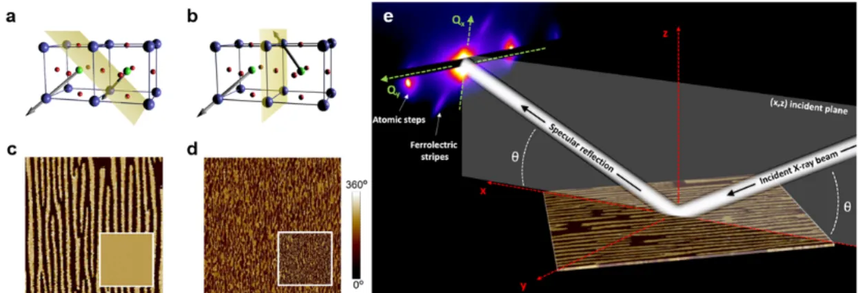
Figure 1: Self-organized ferroelectric patterns and principle of the resonant X-ray diffraction experiments. 79
Schematics of a, the 71° domain wall in the BiFeO3 / SrRuO3 // DyScO3 epitaxial heterostructure and b, the 109°
80
domain wall in BiFeO3 / La0.7Sr0.3MnO3 // DyScO3 formed by alternating ferroelectric polarization variants. The
81
dark blue, red, and light green spheres stand for bismuth, oxygen, and iron ions, respectively and the light
82
yellow planes represent the orientation of ferroelectric domain walls. The grey arrows represent electrical
83
polarizations. In-plane piezoresponse force microscopy images (4 × 4 µm2
) of c, the 71° and d, the 109°
84
ferroelectric stripe patterns. Insets: corresponding out-of-plane PFM images. e, Sketch of the resonant elastic
3
X-ray scattering experiment in reflectivity geometry with Qx and Qy the directions in reciprocal space defined
86
relative to the incident X-ray beam.
87 88
Two sets of BFO epitaxial layers have been grown by pulsed laser deposition on DyScO3 substrates
89
with buffer layers of either SrRuO3 or La0.7Sr0.3MnO3 (Methods). Because BFO has a rhombohedral
90
symmetry (with a slight monoclinic distortion), 8 ferroelectric variants are possible along the {111} 91
directions in the pseudo-cubic lattice. Mastering growth modes has allowed us to reduce the number 92
of variants leading in some cases to highly ordered ferroelectric patterns. Our two representative 93
samples are composed of ferroelectric stripes as characterized by (vectorial) PFM measurements 94
(Fig. 1c,d). The first one has strong alternating contrast in the in-plane image and flat out-of-plane 95
contrast (Fig. 1c) demonstrating that the stripes correspond to 71° FE domains (Fig. 1a) with a 96
periodicity of about 210 nm. The stripes are less ordered in the second sample with dominant 109° 97
FE domain walls (Fig. 1b) as shown in the two PFM images (Fig. 1d) with a 200 nm characteristic 98
length scale. 99
100
Figure 2: Chiral ferroelectric structures at domain walls. Dichroic patterns demonstrating that chirality is 101
associated to electrical polarization in a, 71° and c, 109° domain walls. Insets: corresponding diffraction
102
patterns around the O K edge (530 eV). In a, two pairs of diffraction spots result from the atomic steps of the
103
substrate (2) and the periodic 71° FE structures (1). In c, three pairs of spots are caused by atomic steps (1) and
104
109° FE structures (2 & 3). Schematics of polarization (black arrows) leading to chiral arrangements for b, 71°
105
and d, 109° domain walls.
4
REXS measurements were performed at the synchrotron Soleil on the SEXTANTS beamline in 107
reflectivity geometry (Methods). In the soft energy range, the technique allows accessing complex 108
charge, magnetic and orbital orders with nanometre spatial resolution. The diffracted intensity of a 109
spatially modulated order in reciprocal space for a scattering vector Q is given by 110
( ) ∝ |∑ ·exp( ∙ )| where is the scattering amplitude of a single atom at position . This 111
scattering amplitude is a sum of several contributions, among which some resonant terms are 112
substantially enhanced when the energy of incoming photons reaches absorption edges. They also 113
strongly depend on polarization states of incoming and scattered photons. For electron dipole 114
transitions and in the approximation of a cylindrical symmetry for the considered atoms, the 115
resonant scattering amplitude REXS can be expanded in a sum of 3 main components15–17: 116
RES= ( ̂ ∙ ̂ ) − ( ̂ × ̂ ) ∙ + ( ̂ ∙ )( ̂ ∙ )
where ̂ and ̂′ are the polarization states in the Jones formalism of the incident and diffracted 117
beams, respectively, , the local magnetization unit vector and , , , the photon-energy-118
dependent resonance factors for, respectively, the monopole, magnetic dipole and quadrupole parts 119
of the scattering amplitude. Interestingly, the second term of the right-hand-side, analogous to 120
circular dichroism in absorption, is sensitive to m whereas the last term, analogous to linear 121
dichroism in absorption, is sensitive to m2 and therefore ideal to probe non-collinear 122
antiferromagnetic orders. In lower symmetry lattices such as in ferroelectrics, parity-odd electric 123
dipoles do not directly contribute in the electron-dipole approximation. However, the orbital 124
deformations associated to the electric polarization via spin-orbit coupling can be probed through 125
the quadrupole part of the scattering amplitude in a more general case18 than the work of Hannon15. 126
The diffraction patterns at the O K edge of Fig. 2a,c indeed provide information about the ordering of 127
the orbital quadrupole moments reflecting the ferroelectric stripe networks. For the 71° domain 128
walls, the diffraction peaks (‘1’ in Fig. 2a) correspond to a ferroelectric stripe pattern with a period of 129
218 nm ± 20 nm, as well as more intense ‘parasitic’ peaks (‘2’ in Fig. 2a at 49°) generated by the 130
atomic steps stemming from the miscut of the substrate. This is fully consistent with atomic- and 131
piezoforce- microscopy measurements (Methods and Supplementary Fig. 1). The case of the 109° 132
sample is slightly subtler (Fig. 2c) as three populations can be identified. The intense round spots 133
come from the atomic steps (‘1’ in Fig. 2c), while the two weaker ones (‘2’ & ‘3’ in Fig. 2c) come from 134
the ferroelectric patterns. These correspond to two different period directions: the main (vertical) 135
stripe structure and some less visible oblique terminations. Interestingly, these diffraction spots 136
exhibit a clear circular dichroism (Fig. 2a,c), which disappears off-resonance (the full energy 137
dependence is detailed in Supplementary Fig. 3). This dichroism happens for both systems and 138
reaches 30 % for the main family of spots of the 109° DWs and 2% for the 71° DWs. The smaller 139
dichroism of the latter is mainly due to the measuring angle, imposed by the blinding from the 140
diffracted spots of the regular atomic steps at other angles. 141
Although X-rays cannot directly access electrical polarization in the electron-dipole approximation, 142
they can however indirectly be sensitive to chiral polar arrangements19,18. The dichroism at the O K 143
edge therefore indicates the presence of chirality in the ferroelectric order. This is only possible if the 144
polarization does not vanish at the domain walls, which are non-Ising like, in agreement with recent 145
reports20. This also imposes a homochiral FE winding (Fig. 2b,d), inconsistent with a zigzag winding of 146
DWs linking in the simplest way, the polarizations on each side. It is easy to imagine how this is 147
possible for 109° DWs as going from say the P3+ polarization direction of the first domain to the P4- of
148
the second rotating via P3- or via P4+ are energetically degenerate (Fig. 2d). Thus, although we do not
149
know what forces such a state, our measurements indicate that the two windings alternate: via P3- in
150
one set of DWs and via P4+ for the neighbours, thus imposing a net chirality. Note that a slight
151
dichroism is also visible at the Fe L edge (not shown), which finds a similar explanation as recently 152
developed by Lovesey and van der Laan18 and therefore corroborate the polar chirality in our 153
systems. The case of the 71° DWs is more puzzling as a homochiral state imposes every second wall 154
to wind in a ‘long angle’. For instance, when P directly rotates from P4- to P3- in one DW, it then goes
5
from P3- to P3+ then P4+ to reach P4- in the neighbouring one (Fig. 2b). This is obviously higher in
156
energy than the direct P3- to P4- route and singles out the nature of this set of walls. Note here that
157
P3+ and P4+ regions are not visible in the PFM images implying that they are narrow, but their
158
presence makes the whole FE structure chiral. 159
160
Figure 3: Non-collinear magnetic structure in ferroelectric domains by neutron and resonant X-ray scattering. 161
a, X-ray diffraction at the Fe L edge (707.5 eV) for the 71° periodic ferroelectric patterns. The four main spots 162
(pointed by blue and yellow arrows) visible in a stem from the two families of cycloids sketched in c and
163
correspond to a cycloidal period of about 80 nm. b, Neutron scattering measurements (integrated intensity and
164
2D in inset) show the splitting of the Bragg peaks confirming the cycloidal order. Open circles are experimental
165
data and solid lines are fits assuming a bulk-like spin cycloid with a period of 80 nm. c, Sketch of the two
166
cycloids (one in each polarization domain) propagating in BiFeO3. Pi and Qi stand for the polarization vector of
167
the domains and the wavevector of the cycloids, respectively.
168 169
Turning now to the magnetic order, the (circularly polarized) X-ray wavelength is tuned to the Fe L 170
edge (Methods and Supplementary Fig. 2). The measured REXS diffraction patterns are now 171
completely different, as four peaks appear in a square pattern as shown in Fig. 3a for the 71° FE 172
stripe sample. These should be viewed as paired symmetrically with respect to the specular beam 173
(thus in diagonal). They stem from two cycloidal families, one in each ferroelectric domain, with their 174
propagation vector in the film plane and perpendicular to the local polarizations. This is also 175
confirmed by time of flight neutron diffraction measurements (Fig. 3b, see Methods and 176
Supplementary Fig. 5). Thus, only one out of the three symmetry allowed cycloidal families is present 177
in each polarization domain (Fig. 3c), as the monoclinic distortion lowers further the initial 3-fold 178
symmetry. The period is found to be 80 ± 8 nm, a little greater than the bulk period (64 nm). A closer 179
examination of the elongated shape of the diffraction peaks indicates that they are actually 180
composed of two spots, which stem from a splitting of the cycloidal AF peaks due to the modulation 181
caused by the FE stripe pattern. Polarized X-rays and neutrons have the further capability to locate 182
the spins direction, as previously demonstrated in BFO21,22,23. To our knowledge, the extra ability of 183
both techniques to study the chiral nature of the AF arrangements has not been applied to BFO thin 184
films. With their ultra-high intensity, synchrotron X-rays are the ideal probe of chirality in thin films. 185
This was previously demonstrated in ferromagnets by analysing circular dichroism, i.e. the intensity 186
difference between right and left polarized X-rays24. The magnetic scattering term used to measure 187
ferromagnetic chirality is − ( ̂ × ̂ ) ∙ . Here, we extend this type of analysis to antiferromagnetic 188
chiralities through the ( ̂ ∙ )( ̂ ∙ ) term, giving rise to diffraction peaks located at 2qcycloid in
189
reciprocal space. Similarly, the dichroic plot of Fig. 4a for the 71° sample shows that +q and –q spots 190
have opposite dichroism, indicating that the antiferromagnetic cycloids are chiral. This change of sign 191
also reverses after an azimuthal sample rotation of 180° (Methods and Supplementary Fig. 4), which 192
is consistent with a winding uniquely linked to the direction of P in each ferroelectric domain as 193
expected theoretically25 and measured in the bulk23. We point out here that this feature cannot be 194
due to the (non-chiral) periodic magnetic uncompensation, which would appear at qcycloid in
195
reciprocal space. 196
6 197
Figure 4: Chiral magnetic textures at ferroelectric domain walls seen in reciprocal and real spaces. a, Intensity 198
difference between left and right X-ray polarizations for the two-cycloid system showing opposite dichroism for
199
each set of diffraction spots taken as a signature of chirality. b, Scanning NV magnetometry image of the stray
200
field 60 nm above the sample confirming in real space the two cycloidal populations and the rectangular array
201
of bubbles at ferroelectric domain walls. c-d, Magnetic simulations using an atomistic code and showing the
202
cycloidal arrangements in (a four-atom-thick slab of) the FE stripe domains, as well as their stitching at the
203
walls (d). Every second wall, the polarization (black arrows) rotates along a long winding consistent with the
204
chirality measured for the FE order. The stray field extracted from the simulations (c) shows excellent
205
agreement with NV magnetometry in b.
206
In addition, the diffraction pattern of Fig. 4a comprises some extra features in the form of spots 207
spreading along horizontal lines. These are representative of periodic structures generated by the FE 208
stripes. Indeed, the two pairs of bright spots have a horizontal separation corresponding to the FE 209
stripes’ period of about 220 nm and a vertical separation giving 120 nm in real-space, close to the 210
length of the cycloids projected onto the DWs (√2 × 80 nm). Therefore, this pattern results from the 211
merging of the cycloids at the periodic domain walls. Importantly, its dichroic character indicates that 212
the structures are chiral. Moreover, the weaker middle spots have an intensity inconsistent with the 213
individual diffraction of two periodically striped cycloidal families. We thus attribute their presence 214
to the diffraction of a chiral rectangular pattern stemming from the stitching of the cycloids. 215
To corroborate the presence of these chiral objects, we have combined REXS with real-space imaging 216
by means of scanning NV magnetometry (Methods)26,27. Fig. 4b shows a magnetic image in a sample 217
with 71° DWs grown under the exact same conditions. In addition to a vertical periodicity 218
corresponding to the cycloids in different domains, regular bright spots are visible along one domain 219
7
wall out of two. They are therefore related to the different cycloidal windings. It is worth noting that 220
in the simplest case of the short angle rotation of the ferroelectric polarization, the AF cycloid 221
stitching can be straightforwardly almost continuous. In that case, the discontinuity in magnetization 222
is minimum and the stray field should be close to that in the domain. On the other hand, for a wall 223
with the FE polarization rotating along the long angle (as sketched in Fig. 2b), a frustration appears 224
and the stitching is more complex. Interestingly, the measured hot spots on the scanning NV 225
magnetometry image can be considered as the embryos of multi-q topological objects, especially as 226
the dichroic diffraction patterns evidence their chirality. In order to better illustrate this DW effect, 227
we have carried out numerical simulations using a dynamical atomistic magnetic simulations code28. 228
We minimized the convergence time by dividing all distances by 10 and correspondingly multiplying 229
by 10 the magnetoelectric interactions. This scaling does not affect the qualitative topography of the 230
calculated magnetic configuration (Methods and Supplementary Fig. 6). The underlying striped FE 231
state is taken with a 1-nm slab of a reversed polarization inserted every second wall to account for 232
the ‘reverse winding’. Fig. 4d shows the obtained spin arrangement where AF cycloids are clearly 233
visible in the stripes and a peculiar stitching is observed on the walls where the FE polarization 234
rotates along the wide angle. The stray field generated by the uncompensated moments shows 235
excellent agreement with the recorded scanning NV magnetometry image (Fig. 4c) and notably the 236
hot spots measured every second wall. This provides further evidence supporting our conclusions on 237
both electric and magnetic chiralities. Because of the magnetoelectric interaction, these are 238
entangled at domain walls to create very special entities. Our results call for a proper hybrid 239
modelling of these peculiar objects and of their interplay with charge currents, spin currents and 240
light, in analogy with the topological Hall effect29 and related emergent electromagnetic 241
phenomena30 predicted for skyrmion systems. 242
243
Acknowledgments
244
We thank Horia Popescu for his assistance during the synchrotron runs, Antoine Barbier for 245
discussions regarding diffraction as well as Yves Joly and Gerrit van der Laan for fruitful discussions 246
about theoretical aspects of resonant x-ray scattering. We also acknowledge the company QNAMI for 247
providing all-diamond scanning tips containing single NV defects. V.J. acknowledges financial support 248
by the European Research Council (ERC-StG-2014, Imagine). The authors also acknowledge support 249
from the French Agence Nationale de la Recherche (ANR) through projects Multidolls, PIAF and 250
SANTA as well as the ‘programme transversal CEA ACOSPIN and ELSA’. This work was also supported 251
by a public grant overseen by the ANR as part of the ‘Investissement d’Avenir’ programme (LABEX 252
NanoSaclay, ref. ANR-10-LABX-0035). 253
254 255
Authors contributions:
256
JYC, MV and NJ planned the REXS experiment and carried it out with CB. VG and SF prepared the 257
samples and carried out the PFM measurements. BD, DK and PM carried out the neutron 258
measurements while WA, IG, IF and VJ carried out the NV magnetometry. TC, JT and PT wrote, 259
optimized and ran the simulation code. All authors participated in scientific discussions. 260
261
Data Availability: All relevant data are available from the authors, and/or are included with the
262
manuscript. 263
264 265
8
References
266
1. Emori, S., Bauer, U., Ahn, S.-M., Martinez, E. & Beach, G. S. D. Current-driven 267
dynamics of chiral ferromagnetic domain walls. Nat. Mater. 12, 611–616 (2013). 268
2. Fert, A., Reyren, N. & Cros, V. Magnetic skyrmions: advances in physics and potential 269
applications. Nat. Rev. Mater. 2, 17031 (2017). 270
3. Barker, J. & Tretiakov, O. A. Static and Dynamical Properties of Antiferromagnetic 271
Skyrmions in the Presence of Applied Current and Temperature. Phys. Rev. Lett. 116, 272
147203 (2016). 273
4. Nahas, Y. et al. Discovery of stable skyrmionic state in ferroelectric nanocomposites. Nat.
274
Commun. 6, 8542 (2015).
275
5. Pereira Gonçalves, M. A., Escorihuela-Sayalero, C., Garca-Fernández, P., Junquera, J. & 276
Íñiguez, J. Theoretical guidelines to create and tune electric skyrmion bubbles. Sci. Adv. 277
5, eaau7023 (2019). 278
6. Jungwirth, T., Marti, X., Wadley, P. & Wunderlich, J. Antiferromagnetic spintronics. Nat. 279
Nanotechnol. 11, 231–241 (2016).
280
7. Wadley, P. et al. Electrical switching of an antiferromagnet. Science 351, 587–590
281
(2016). 282
8. Smolenskii, G. A. & Chupis, I. E. Ferroelectromagnets. 20 (1982). 283
9. Dzyaloshinsky, I. A thermodynamic theory of “weak” ferromagnetism of 284
antiferromagnetics. J. Phys. Chem. Solids 4, 241–255 (1958). 285
10. Seidel, J. et al. Conduction at domain walls in oxide multiferroics. Nat. Mater. 8, 229–234 286
(2009). 287
11. Van Aert, S. et al. Direct Observation of Ferrielectricity at Ferroelastic Domain 288
Boundaries in CaTiO 3 by Electron Microscopy. Adv. Mater. 24, 523–527 (2012). 289
12. Wei, X.-K. et al. Ferroelectric translational antiphase boundaries in nonpolar materials. 290
Nat. Commun. 5, (2014).
9
13. Bhattacharya, K. APPLIED PHYSICS: The Material Is the Machine. Science 307, 53–54 292
(2005). 293
14. Catalan, G. & Scott, J. F. Physics and Applications of Bismuth Ferrite. Adv. Mater. 21, 294
2463–2485 (2009). 295
15. Hannon, J. P., Trammell, G. T., Blume, M. & Gibbs, D. X-Ray Resonance Exchange 296
Scattering. Phys. Rev. Lett. 61, 1245–1248 (1988). 297
16. Hill, J. P. & McMorrow, D. F. X-ray Resonant Exchange Scattering: Polariztaion 298
Dependence and Correlation Function. Acta Crystallogr. A 52, 236–244 (1996). 299
17. van der Laan, G. Soft X-ray resonant magnetic scattering of magnetic nanostructures. 300
Comptes Rendus Phys. 9, 570–584 (2008).
301
18. Lovesey, S. W. & van der Laan, G. Resonant x-ray diffraction from chiral electric-302
polarization structures. Phys. Rev. B 98, 155410 (2018). 303
19. Shafer, P. et al. Emergent chirality in the electric polarization texture of titanate 304
superlattices. Proc. Natl. Acad. Sci. 115, 915–920 (2018). 305
20. Cherifi-Hertel, S. et al. Non-Ising and chiral ferroelectric domain walls revealed by 306
nonlinear optical microscopy. Nat. Commun. 8, 15768 (2017). 307
21. Waterfield Price, N. et al. Coherent Magnetoelastic Domains in Multiferroic BiFeO 3 308
Films. Phys. Rev. Lett. 117, (2016). 309
22. Lebeugle, D. et al. Phys Rev Lett 100, 227602 (2008). 310
23. Johnson, R. D. et al. X-Ray Imaging and Multiferroic Coupling of Cycloidal Magnetic 311
Domains in Ferroelectric Monodomain BiFeO 3. Phys. Rev. Lett. 110, (2013). 312
24. Dürr, H. A. et al. Chiral magnetic domain structures in ultrathin FePd films. Science 284, 313
2166–2168 (1999). 314
25. Mostovoy, M. Ferroelectricity in Spiral Magnets. Phys. Rev. Lett. 96, (2006). 315
10
26. Rondin, L. et al. Magnetometry with nitrogen-vacancy defects in diamond. Rep. Prog. 316
Phys. 77, 056503 (2014).
317
27. Gross, I. et al. Real-space imaging of non-collinear antiferromagnetic order with a single-318
spin magnetometer. Nature 549, 252–256 (2017). 319
28. Tranchida, J., Plimpton, S. J., Thibaudeau, P. & Thompson, A. P. Massively parallel 320
symplectic algorithm for coupled magnetic spin dynamics and molecular dynamics. J. 321
Comput. Phys. 372, 406–425 (2018).
322
29. Bruno, P., Dugaev, V. K. & Taillefumier, M. Topological Hall Effect and Berry Phase in 323
Magnetic Nanostructures. Phys. Rev. Lett. 93, (2004). 324
30. Nagaosa, N. & Tokura, Y. Emergent electromagnetism in solids. Phys. Scr. T146, 014020 325
(2012). 326
327 328
11
Methods
329
Sample preparation and characterization
330
The epitaxial thin film heterostructures were grown by pulsed laser deposition using a KrF excimer 331
laser (λ = 248 nm, 1 J cm−2) on an orthorhombic DyScO3 (110)o single crystal substrate. The SrRuO3
332
(resp. La1/3S2/3rMnO3) bottom electrode (1.2 nm) was grown with 5 Hz repetition rate at 650 °C under
333
0.2 mbar of oxygen for the sample exhibiting 71° (resp. 109°) stripe domains. The BiFeO3 films (32
334
nm) were subsequently grown at 650 °C under 0.36 mbar of oxygen at 1 Hz repetition rate. The 335
heterostructures were slowly cooled down under high oxygen pressure. In both cases, the film 336
surface exhibits single-unit-cell atomic steps (with additional ferroelastic deformations related to the 337
ferroelectric variants of the 109° sample). 338
The structural thin film properties were assessed by X-ray diffraction (XRD, Xpert Panalytical) 339
performing reciprocal space mappings (RSMs) along different directions of the monoclinic DyScO3
340
substrate. PFM experiments were conducted with an atomic force microscope (Nanoscope V 341
multimode, Bruker) and two external SR830 lock-in detectors (Stanford Research) for simultaneous 342
acquisition of in-plane and out-of-plane responses. A DS360 external source (Stanford Research) was 343
used to apply the AC excitation to the bottom electrodes at a frequency of 35 kHz while the 344
conducting Pt coated tip was grounded. The ferroelectric configurations of the pristine BFO samples 345
were identified by vectorial PFM, i.e. probing the different in-plane variants when rotating the 346
sample crystallographic axes compared to the PFM cantilever long axis. Alternated light/dark stripes 347
are observed in the in-plane PFM phase image acquired with the cantilever aligned along the 348
pseudo-cubic 100C direction.
349
The PFM and AFM images show structures that can be compared to the resonant scattering 350
diffraction through FFT transforms. Two different features can be attributed to diffraction by 351
substrate atomic steps and electrical polarization stripes, but peak No3 of the REXS does not appear 352
in the PFM+AFM images. We attribute it to some domains’ terminations, which can be guessed from 353
the real-space PFM image but not ordered enough to appear in the Fourier transforms. 354
Resonant soft x-ray elastic scattering
355
A. Experimental details and setup configuration 356
The experiment has been performed at SOLEIL synchrotron on the SEXTANTS beamline in the RESOXS 357
[31] diffractometer. The diffractometer is equipped with a CCD camera (2048x2048 pixels of 13.5μm) 358
that is on the detector arm at 26 cm from the sample. The solid angle probed by the camera alone is 359
6.3° but it can be further moved perpendicularly to the scattering plane by +/- 15mm to increase the 360
accessible reciprocal space. A set of beamstops placed a few mm before the CCD chip can be 361
precisely aligned with few 10nm precision in order to block the specular beam or unwanted strong 362
Bragg reflections. 363
Data were collected at both O K edge and Fe L edges using circularly polarized x-rays delivered from 364
an Apple 2 undulator located at the I14M straight section of SOLEIL storage ring. A typical photon flux 365
of 1013ph/s with 100meV energy resolution was used for the experiment. 366
367
B. Energy dependence 368
Prior to any conclusions relating to circular dichroism and chirality, the energy dependence of circular 369
dichroic diffraction patterns has been measured both around the Fe L3 edge and the O K edge.
370
Supplementary Fig. 2 presents the normalized circular dichroism for the upper diffraction pattern as 371
12
function of the incident photon energy around the Fe L3 edge. The dashed line stands for the
372
normalized specular intensity at an incident x-ray angle of 30°. On the left side of the figure, a 373
selection of normalized circular dichroisms of the cycloidal diffraction patterns are presented. As 374
expected, there is no signal off-resonance and two maxima are observed for the 2p to 3d t2g
375
transition (707.5 eV) and about 1 eV above the 2p to 3d eg transition (710 eV). However, when
376
reaching the maximum of the main resonance (709 eV), the circular dichroism is either vanishing or 377
even reversing. Yet, at this energy, the intensity is one order of magnitude larger and additional 378
effects might play a non-negligible role. Indeed, dynamical effects and phenomena such as x-ray 379
birefringence [32] or magneto-optical effects [33] are known to occur. One crucial consequence is 380
that the X-ray polarization could be modified during the crossing of the material (and not only by 381
scattering processes). Because it is challenging to account for these processes, we have avoided this 382
energy for the analysis of the magnetic chirality. A similar argument holds for the O K edge, as can be 383
seen in Supplementary Fig. 3. A strong energy dependence is evidenced, yet no inversion of circular 384
dichroism is observed in the peaks under consideration. It is interesting to notice that the maxima in 385
circular dichroism are found in the feet of the main resonances. 386
387
C. Azimuthal dependence 388
Topological structures generate a dichroic signal that is of opposite sign in +q and –q. This depends 389
on the sign of the chirality and it is therefore linked to the antiferromagnetic winding in the sample. 390
This provides us with another means to further confirm that the dichroism stems from the AF 391
cycloids. Indeed, as Supplementary Fig. 4 shows, the dichroism reverses when the sample is rotated 392
by 180° in the azimuthal plane. 393
Neutron scattering
394
We used time of flight neutron diffraction to confirm the presence of the cycloidal ordering in our 395
BFO/DSO thin film. The measurements were carried out in four different scattering geometries 396
schematically shown in Supplementary Fig. 5. For each sample orientation (angle φ in Supplementary 397
Fig. 5a), two distinct pseudo-cubic diagonals {111}D-type, referring to the DSO substrate unit cell,
398
were in the scattering plane, but as only one of them could be optimized with respect to the neutron 399
flux and resolution for the target magnetic reflections, two measurements (angle ω in 400
Supplementary Fig. 5a) were performed. The target reflections were the satellites of the {½½½}±k 401
type expected at a d-spacing range around 4.5-4.6 Å. The measurements were performed at high 402
scattering angles (typically above 120°) to achieve a good momentum transfer resolution and the 403
reflecting geometry helped to avoid absorption from the substrate. After 16 hours of exposition time, 404
the (hhh)-type reflections of the BFO film could be clearly observed (Supplementary Fig. 5b,c). In two 405
out of the four scattering geometries, two signals, spatially separated from the substrate on the 406
detectors array, could be resolved (Supplementary Fig. 5b), revealing the presence of structural 407
domains. In the other two measurements, the domains could not be resolved (Supplementary Fig. 408
5c). Data, focused around these (hhh)-type reflections and plotted as a function of d-spacing, are 409
presented in Supplementary Fig. 5d-f. The patterns clearly reveal the presence of magnetic 410
reflections in the expected d-spacing range. The magnetic satellites scatter very close to the nuclear 411
(hhh)-type reflections and the angular resolution of the data is not sufficient to spatially isolate the 412
nuclear and magnetic reflections on the detector array. The d-spacing positions and intensities of the 413
observed magnetic reflections can be quantitatively fitted by the model implying a cycloidal magnetic 414
order, similar to that in bulk BFO, and the presence of two equi-populated ferroelectric domains 415
illustrated in Supplementary Fig. 5g,h. It is remarkable that the data can be satisfactorily modelled 416
only assuming a single magnetic domain state with the propagation vector k=(-δ,0,δ), δ≈0.043(3) for 417
both ferroelectric domains. As possible reasons for suppression of the other two magnetic domains 418
13
with k2=(0,-δ,δ) and k3=(-δ,δ,0) is the small monoclinic distortion of the ferroelectric domains
419
imposed by the misfit with the substrate as discussed below. 420
The pseudocubic unit cell metric of the orthorhombic DSO substrate (Supplementary Fig. 5i) is 421
characterised by two distances (aD=cD≠bD) and one angle (βD≠90). This implies two non-equivalent
422
{100}-type BFO films with the bD-axis either parallel or perpendicular to the surface. In our case, the
423
bD-axis is parallel to the surface. The unit cell is also characterised by two long [11-1]D/[1-1-1]D and
424
two short [111]D/[1-11]D diagonals as shown in Supplementary Fig. 5i. Our neutron diffraction data
425
indicate that this type of substrate imposes a selection of two ferroelectric domains in the BFO film. 426
The polar [111] axes of these domains are along the long diagonals [11-1]D and [1-1-1]D of the
427
substrate (Supplementary Fig. 5g-i). Moreover, the pseudocubic unit cell metric of the BFO film 428
(af=bf=cf, αf=βf=γf≠90°) does not match the metric of the substrate, resulting in additional structural
429
distortions. These could be responsible for the selection of the single magnetic domain state, 430
through magneto-elastic coupling, within the structural ferroelectric domains. The resolution of our 431
neutron diffraction data, however, is not sufficient to directly measure these distortions. 432
In the scattering geometries optimized to measure magnetic satellites, close to the (11-1)D and
(1-1-433
1)D reflections, the two domains cannot be separated and a contribution from both domains is
434
present in the focused data (Supplementary Fig. 5c,f). The refined value of the propagation vector 435
δ=0.043(3) is slightly smaller than that of the bulk BFO indicating a slightly longer period of the 436
cycloidal modulation with respect to that of the bulk. This is in a good agreement with the 437
synchrotron data. 438
Scanning NV magnetometry
439
Scanning-NV magnetometry is performed with a commercial all-diamond scanning-probe tip 440
containing a single NV defect (QNAMI, Quantilever MX). This tip is integrated into a tuning-fork-441
based atomic force microscope (AFM) combined with a confocal microscope optimized for single 442
defect spectroscopy. Details about the experimental setup can be found in [34]. Quantitative 443
magnetic field distributions are obtained by monitoring the Zeeman shift of the NV defect electron 444
spin sublevels through optical detection of the magnetic resonance [35]. Experiments are performed 445
under ambient conditions with a NV-to-sample distance of 60 nm. 446
Atomistic spin dynamic computation
447
Unlike micromagnetic simulations applied to ferromagnets, large-scale simulations of complex 448
antiferromagnetic textures remain a challenge. Indeed, the micromagnetic approximation consisting 449
in averaging local magnetic moments into large enough computational cells and supposing that this 450
quantity only changes in direction and not in magnitude, fails for antiferromagnets. In order to 451
provide a simulation support for our experimental findings, atomistic spin dynamics simulations have 452
been performed where each atom carries a spin. The relevant interactions for BFO have been 453
considered, namely exchange, magnetoelectric, anisotropy and asymmetric Dzyaloshinskii-Moriya 454
interactions on a periodically striped ferroelectric pattern. In order to model as closely as possible 455
the antiferromagnetic configurations of our samples, the ferroelectric domain walls have been 456
designed as measured, with a chiral winding. For the 71° pattern, one wall out of two was taken to 457
rotate following the ‘long winding’ schematically represented in Fig. 4b of the main text. The 458
simulations have been carried out using the SPIN package of LAMMPS [36, 37] which assesses spin 459
textures and their dynamics by solving the Landau-Lifshitz-Gilbert (LLG) equation : 460
14
with the unit spin vector at the ith position, the Gilbert damping coefficient and the effective 461
spin pulsation defined as: 462
=−1 ℏ
For the present study, the three main components of the Hamiltonian ( ) of N interacting spins are 463
considered, namely the symmetric exchange, the magneto-electric (ME) and the asymmetric 464
Dzyaloshiskii-Moriya interactions (DM) expressed as follows: 465
= − , ,
∙ + × ∙ × + × ∙ ×
with the symmetric exchange coefficient, the unit direction vector between the ith and jth 466
spins, the global ferroelectric polarization and the local polarization induced by the octahedral 467
tilts and alternating from site to site. Noteworthy, the consequence of this latter is the small cycloidal 468
wriggling leading to an apparent spin density wave. 469
The simulations have been performed for N=Nx (240)*Ny (172)*Nz(4) spins with periodic boundary
470
conditions in x and z. A cubic lattice with a 3.96 Å constant was considered. The x-direction 471
corresponds to the (100) crystallographic direction. Note that while the antiferromagnetic exchange 472
interaction has been kept to its known value (-4.5 meV for nearest neighbour interaction), ME and 473
DM interactions were multiplied by a factor 10 (1.09 meV and 0.54 meV respectively) to reduce the 474
simulated volume and hence the calculation time. The cycloidal period scales correspondingly. 475
The spins are divided into 60 atom wide stripes with different orientations of in order to mimic the 476
71° ferroelectric striped pattern. Every second ferroelectric domain wall is defined following the 477
assumptions explained in the article. The result is shown in Supplementary Fig. 6. 478
Subsequently, the magnetic stray field of the converged spin texture is calculated and projected 479
along the NV defect quantization axis [34], leading to the result shown in figure 4 d of the main 480 article. 481 482 References 483 484
[31] N. Jaouen, J.-M. Tonnerre, G. Kapoujian, P. Taunier, J.-P. Roux, D. Raoux, and F. Sirotti, J. 485
Synchrotron Radiat. 11, 353 (2004). 486
[32] Y. Joly, S. P. Collins, S. Grenier, H. C. N. Tolentino, and M. De Santis, Phys. Rev. B 86, 220101 487
(2012). 488
[33] M. W. Haverkort, N. Hollmann, I. P. Krug, and A. Tanaka, Phys. Rev. B 82, 094403 (2010). 489
[34] L. Rondin et al., Appl. Phys. Lett. 100, 153118 (2012). 490
[35] L. Rondin, et al., Rep. Prog. Phys. 77, 056503 (2014). 491
[36] S. Plimpton, J. Comput. Phys. 117, 1 (1995). 492
[37] J. Tranchida, S. J. Plimpton, P. Thibaudeau, and A. P. Thompson, J. Comput. Phys. 372, 406 493
(2018). 494
0° 360°
a
b
d
P
3-P
3+a
c
b
d
71°
109°
P
3-P
4-P
4-P
4+P
3+P
4 + 1 2 1 2 3P
3-P
4-P
3-P
3+P
4+P
4-0.04 nm
-10.04 nm
-1-30%
30%
N
or
maliz
ed
cir
cu
lar
d
ic
h
roism
-6%
3%
N
or
maliz
ed
cir
cu
lar
d
ic
h
roism
𝟏𝟏𝟏𝐁 ഥ 𝟏 𝟐 ഥ 𝟏 𝟐 𝟏 𝟐 𝐁 − 𝒌 ഥ 𝟏 𝟐 ഥ 𝟏 𝟐 𝟏 𝟐 𝐁 + 𝒌 2.3 4.5 4.6 4.7 0 1 2 3 4