HAL Id: cea-02972474
https://hal-cea.archives-ouvertes.fr/cea-02972474
Submitted on 20 Oct 2020HAL is a multi-disciplinary open access archive for the deposit and dissemination of sci-entific research documents, whether they are pub-lished or not. The documents may come from teaching and research institutions in France or abroad, or from public or private research centers.
L’archive ouverte pluridisciplinaire HAL, est destinée au dépôt et à la diffusion de documents scientifiques de niveau recherche, publiés ou non, émanant des établissements d’enseignement et de recherche français ou étrangers, des laboratoires publics ou privés.
A full reference APOLLO3
®deterministic scheme for the
JHR material testing reactor
Matthieu Lebreton, Julien Politello, Jean-François Vidal, G. Rimpault
To cite this version:
Matthieu Lebreton, Julien Politello, Jean-François Vidal, G. Rimpault. A full reference APOLLO3® deterministic scheme for the JHR material testing reactor. PHYSOR 2020 - Transition to a Scalable Nuclear Future, Mar 2020, Cambridge, United Kingdom. �cea-02972474�
A FULL REFERENCE APOLLO3
®DETERMINISTIC SCHEME FOR THE
JHR MATERIAL TESTING REACTOR
Matthieu LEBRETON, Julien POLITELLO, Jean-François VIDAL, Gérald RIMPAULT
Commissariat à l’Energie Atomique et aux Energies Alternatives
CEA, DEN, DER, SPRC, Cadarache, F-13108 Saint-Paul-Lez-Durance, France
[email protected], [email protected], [email protected],
[email protected]
ABSTRACTJHR is a new material testing reactor under construction at CEA Cadarache. Its high flux core contains 37 fuel assemblies loaded along concentric rings into alveolus of an aluminum matrix. For the operation of the reactor, twenty-seven of these fuel assemblies host hafnium rods in their center while the other ones but also the beryllium radial reflector can accommodate experimental devices. In order to accurately predict its operating core characteristics but also its irradiation performance, a recently developed scheme based on the APOLLO3® platform is
being developed which uses the sub-group method for spatial self-shielding, the 2D method of characteristics and the 3D unstructured conform MINARET Sn transport solver.
A 2D model of JHR has been built and optimized for calculating, at the lattice step, the self-shielded and condensed cross sections thanks to the sub-group method and the method of characteristics. Results are benchmarked against a TRIPOLI-4® stochastic reference
calculation. A more refined spatial mesh gives better results on fission rates and reactivity compared to the ones of the former APOLLO2 scheme.
The classical 2-step calculations use the hypothesis of infinite lattice configuration, which is reasonable for the assemblies close to the center but not for peripheral ones. Hence, a new approach is being set up taking into account the surrounding of each assembly. The newly 3-step scheme uses the Sn solver MINARET and gives better results than the traditional 2-3-step scheme. This approach will be applied to a 3D modelling of the heterogeneous JHR core configurations incorporating experimental devices and enabling burn up calculations.
KEYWORDS: APOLLO3®, JHR, Deterministic calculation scheme, S
n method
1. INTRODUCTION
The Jules Horowitz Reactor (JHR) [1] is a new material testing reactor under construction at CEA Cadarache in the south of France. The main objective of this research reactor is to test advanced materials and to demonstrate their ability to withstand proper characteristics under operation conditions and irradiation. This concerns the safety whether it is for new generations (GEN-III and GEN-IV) nuclear reactors or for current generation (GEN-II). Another goal is to produce 99Mo for medical diagnostics.
Neutronics calculations on JHR are routinely performed with a 2-step deterministic scheme [2].
This neutronic scheme is currently based on the APOLLO2[3]/CRONOS2[4] codes to carry out respectively lattice and core calculations. The aim of this scheme is to predict JHR neutronics characteristics on the real 3D geometry over time. It will help operators to anticipate the behavior of the core, and to
Matthieu Lebreton et al., A full reference APOLLO3
®deterministic scheme for the JHR material
testing reactor
Proceedings of the PHYSOR 2020, Cambridge, United Kingdom
operate it safely. Results of the scheme are benchmarked at the beginning of life against stochastic calculations using the Monte-Carlo method [5] as implemented in the TRIPOLI-4®[6] code. Results at burnup conditions are benchmarked against a 1-step deterministic calculation using the method of characteristics. Currently, the industrial route of the scheme computes the lattice step with depletion for fuel elements with the TDT solver [7] using the Method of Characteristics (MOC) on a refined 2D geometry after a resonance self-shielding treatment. The second step uses the CRONOS2-PRIAM solver based on diffusion theory using condensed/homogenized cross-section generated at the first step. This second step is applied on a homogenized geometry with a 6-group condensed energy mesh. It allows full core depletion calculations. The new APOLLO3® [8] code in development at CEA brings advanced options for deterministic
calculations. New solvers are available, such as the unstructured conform MINARET [9] Sn solver, a 2D/3D
transport solver based on the discrete ordinates method (Sn) whose spatial discretization is relying on a
Discontinuous Galerkin Finite Element Method (DGFEM). A subgroup method for calculating resonance self-shielding is implemented as it was done in the ECCO code. The method is coupled with the TDT flux calculation. It is also possible to create complex core geometry thanks to the SALOME platform [10]. The goal of this work is to design a new full reference deterministic scheme based on APOLLO3® to
perform neutronics calculation on the Jules Horowitz Reactor. This new scheme will be a 3-step scheme in which condensed/homogenized cross-sections from a MOC-2D JHR models will be used to compute with Sn solver a 3D full core model (2rd and 3nd steps). Recent studies have shown that APOLLO3® and its
advanced options significantly improve predictions, more specifically on the reactivity worth of Hafnium control rods [11]. This requires specific energy and spatial meshes. Cross-sections once self-shielded are condensed on a lattice geometry (1st step) prior to the MOC-2D calculation. This approach helps to better
take into account the surroundings of each fuel element.
In this document, the improvements on MOC-2D core step at beginning of life with the new APOLLO3®
solver options are presented. Results are compared with TRIPOLI4®Monte Carlo simulations. The impact
of the 3-step scheme against a classical 2-step scheme is being illustrated.
2. THE JULES HOROWITZ REACTOR
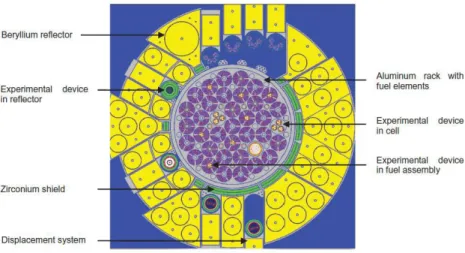
JHR is a 100MW pool research reactor. The core is made of 37 fuel assemblies loaded along concentric rings into alveolus of an aluminum matrix. Fuel assemblies are made of U3SiO2 fuel enriched up to 27 %.
Three of these assemblies can be removed and replaced by in-core experimental devices. Twenty-seven hafnium rods are introduced at the center of fuel assemblies to control the reactivity. It is also possible to place experimental devices at the center of the remaining fuel assemblies or into the beryllium radial reflector. JHR reaches high flux, up to 5.1014 n.cm-2.s-1.
The JHR fuel assemblies consist of 24 curved concentric plates held together thanks to an aluminum stiffener. Light water flows into these fuel assemblies to cool and moderate the fuel (figure 2).
Figure 2. JHR fuel element and JHR Fuel Plate Description.
3. NEW 3-STEP NEUTRONIC SCHEME
Today, the only way to compute JHR core in 3D in depletion, is a 2-step calculation (figure 3). The first step solves the Boltzmann neutrons transport equation for each type of fuel assembly with specular boundary conditions. Space and energy are finely described, cross-sections are taken from the nuclear data library and a resonance self-shielding treatment is implemented to take into account the deeply resonant structure of cross-sections. The neutron flux calculated at each time step creates homogenized/condensed cross-sections stored into Multi-Parameters-Outputs (MPO) files. During the second step, a flux calculation on a coarser energy mesh is now performed on the 3D homogenized geometry for different burn up steps thank to the information stored in MPO. The core calculation solvers are based on diffusion theory or discrete ordinate method. They allow computing macroscopic core parameters for safety studies, and operation.
Matthieu Lebreton et al., A full reference APOLLO3
®deterministic scheme for the JHR material
testing reactor
Proceedings of the PHYSOR 2020, Cambridge, United Kingdom
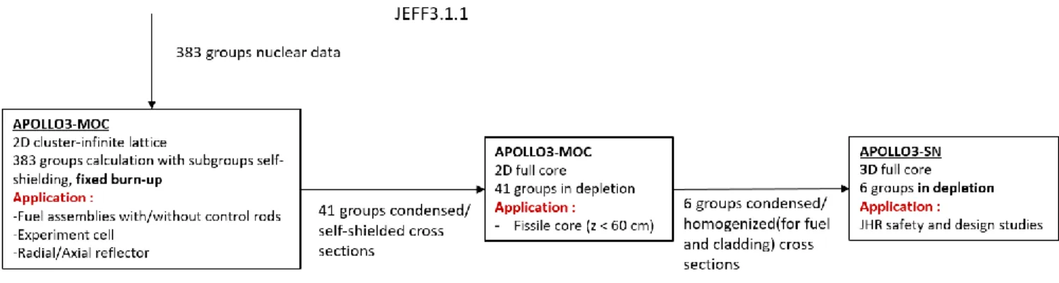
This scheme allows the calculation of the core whereas a 1-step calculation would be too demanding in computing resource. This methodology is particularly suited to large power nuclear core in which an important number of similar fuel assemblies are present. For the JHR, an important quantity of different types of devices can be inserted into a small core. Depending on its neighbors, and their types, each assembly depletes differently according to the local neutron flux. The infinite lattice description of the fuel assemblies is no longer suitable for predicting the behavior of the core.The new 3-step deterministic reference scheme is developed specifically for the JHR. The main objective of this scheme is to better take into account the heterogeneous structure of the JHR compared to the current APOLLO2/CRONOS2 scheme. In the first step, the neutron flux is calculated as for the lattice step of the 2-step scheme, using JEFF3.1.1 [12] nuclear data for the resonance self-shielding treatment. Cross-sections are condensed from 383 groups [13] to 41 groups at a fixed burn-up. In the second step, a full core APOLLO3-MOC2D calculation is performed in depletion using cross sections calculated at the first step. This new step provides a 6-group MPO to use in the 3rd step corresponding to the 3D core calculation. In
our application, the core calculations at this 3rd step is performed with the MINARET-S
n and
MENDEL-depletion solvers at different burn up steps.
The main difference between this scheme and a 2-step scheme is the intermediate step that calculates the flux on the 2D core. Indeed, in each element of the core, flux shape is different according to its nature and its neighbors. The 2-step scheme takes into account the different natures of the fuel elements, because the MPO is computed for each type of fuel assembly. The 3-step scheme also takes into account the surrounding assemblies. It attempts to describe as precisely as possible the structures around the fuel element with witch it exchanges neutrons. The flux used for homogenization/condensation depending on these exchanges, it is therefore important to consider this surrounding. The global scheme is detailed figure 4.
Figure 4. Description of the 3-step neutronic scheme.
The 2nd step MOC2D calculation has been presented in [11]. This step has been optimized to improve the
results on k-eff and fission rates shape.
4. APOLLO3® MOC-2D CORE CALCULATION
The core configuration studied in this paper consists of 37 fuel assemblies and 5 Hf control rods. It is a 2D study at time step 0 conducted with the solver TDT-MOC using the Method of Characteristics. The calculation options are summarized in figure 4.
Previous work has revealed two main sources of fission rates bias in the preparation of the condensed cross sections (now treated in the two first steps) compared to TRIPOLI4®. This bias is located on the one hand
the bias is mainly due to a too coarse description of the large resonance of 178Hf at 7.8 eV in the 383-energy
mesh. Investigation of the second part of the bias have shown that it partly comes from the water sheet between the Zr screen and the reflector.
Due to its strong anisotropy, it is difficult to predict the neutron flux near the water sheet. To improve the prediction near the reflector, a study of the sensitivity of k-eff on the number of meshes in the reflector has been conducted. It shows the need for a more refined mesh in the reflector as shown in figure 5. The refinement is done mainly for the water sheet and the Be reflector. In these areas, the flux variations are the biggest because they make the transition between the high flux in the core and the low flux in the pool.
Figure 5. Comparison between the former and the new spatial mesh for the MOC2D core calculation.
The results on fission rates for each fuel plates are compared for the two meshes on figure 6 to the stochastic reference ones calculated with TRIPOLI-4®. We can see an important improvement of the prediction of the
fission rates per fuel assemblies. This better agreement is particularly viewable at the surrounding of Zirconium shield. The more refined radial mesh allows a better description of the flux variation in the water sheets and in the Be reflector, which impacts the fission rate calculation. In fact, 6 rings per water sheet are necessary to describe accurately the flux in these regions.
Matthieu Lebreton et al., A full reference APOLLO3
®deterministic scheme for the JHR material
testing reactor
Proceedings of the PHYSOR 2020, Cambridge, United Kingdom
The new spatial mesh for the MOC calculation gives also a better prediction of the reactivity. For the former mesh, the reactivity bias compared to TRIPOLI-4® is -45 pcm (keffTR4 = 1.39490). For the new scheme, the
bias in reactivity is -31 pcm.
5. APOLLO3® SN CALCULATION
As explained on figure 4, the MOC-2D core calculation is used to generate homogenized/condensed MPO for a Sn 3D core calculation. The APOLLO3® S
n solver is MINARET. The performances of the 3-step
scheme are tested with a MINARET 2D calculation on the same configuration than the MOC calculation. In this part, the biases with the stochastic reference between the 2-step and the 3-step scheme (table 1) are compared. This will lead in the future to MINARET 3D calculations.
The MINARET solver uses a conformal triangular mesh to discretize the geometry as shown in figure 7.
Figure 7. Geometry and mesh for the MINARET-Sn core calculation.
The cross-sections are obtained from the lattice step for the 2-step scheme, and from the MOC-2D core calculation for the 3-step scheme. The cross-sections for the reflector structures are homogenized/condensed in both cases from the MOC-2D core calculation.
To reach an acceptable running time, cross sections are condensed into six groups. Homogenization is limited, because we want to keep separate each fuel plate (888 volumes). This is a requirement for the scheme design, because we want to compute the power of each plate to obtain the power shape.
To estimate the separate effects of condensation and solver options, the results are compared without condensation at 41 groups with a MOC2D calculation and a MINARET2D Sn calculation.
MOC2D – 41groups (1) MINARET 41groups (2) MINARET 6groups – 2 steps (3) MINARET 6groups – 3 steps (4) ∆k-eff (pcm) -31 +73 +353 +270 ∆plate, min (%) -1.83 -3.96 -5.56 -4.41 ∆plate, max (%) +2.17 +2.48 +2.85 +2.51 Standard deviation 0.95 1.13 1.45 1.22 tcalculation (s) 3700 3400 260 260
Comparison between (1) and (2) shows a small bias between the Sn and MOC solvers for our model. The
bias on each plate is under 4%. The 6-group condensation slightly degrades the prediction, but divides by 13 the execution time (3).
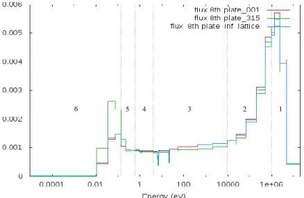
Taking into account the neighboring of each assembly in condensed cross sections with the 3-step calculation limits the degradation, but keeps the same execution time (4). The improvement is greater for fuel assemblies close to the reflector, because the real surrounding of these fuel assemblies is the most different from the infinite lattice one. For assemblies at the core center, the differences are s between the two calculations. Figure 8 shows the normalized flux used to condense the 41-group cross sections into 6 groups for the 8th plate of the center assembly (001), and of an assembly close to the reflector (315). These
two assemblies are identical, but the flux strongly depends of the surrounding, especially for thermal energies. For assembly 001, the infinite lattice approximation seems to be justified, but for assembly 315, the real flux is much more thermal than predicted by the infinite lattice calculation.
Figure 8. Flux in the eighth fuel plate
The 6-group energy mesh is also shown in figure 8. The fissions occur mainly in the group [1.0E-5eV, 1.378E-1eV]. The bias observed on the flux in this group is passes on the 235U condensed fission cross
section used for the MINARET calculation. Compared with the cross section obtained with the infinite lattice model, the bias for element 315 reaches 5 % but only 0.2% for element 001 (table II). This bias contributes to explain the difference between the 2-step and 3-step calculations.
Assembly n° (without Hf) ‘Infinite lattice’ 2D-MOC ‘001’ 2D-MOC ‘315’ 2D MOC
Fission cross section (barn) 403 404 423
Table II. Condensed fission cross-section in group [1.0E-5eV, 1.378E-1eV] for 8th plate
6. CONCLUSION
To deal with the very heterogeneous JHR core, a new 3-step deterministic scheme based on the APOLLO3® code has been designed. Compared to the traditional 2-step scheme, the new 3-step scheme takes into account the surrounding of each fuel assembly. This new methodology uses a MOC-2D core calculation to generate homogenized and condensed cross-sections stored in a multiparameter reactor
database. The 3-step scheme improves the fission rates predictions at the periphery of the core compared
to the 2-step one. It limits the impact of the energy mesh condensation and gives a much more accurate and1 2 3 4 5 6
Matthieu Lebreton et al., A full reference APOLLO3
®deterministic scheme for the JHR material
testing reactor
Proceedings of the PHYSOR 2020, Cambridge, United Kingdom
faster computation of fission rates with MINARET solver. The reduction of the bias on fission rates (vs TRIPOLI4 Monte Carlo results) near to the Zr screen of the reflector reaches ~1.4% against more than 3% without the new spatial mesh.Finally, this fast Sn calculation with MINARET enables calculating 3D core configurations with
experimental devices and control rods. It paves the way to a full reference APOLLO3® deterministic scheme
for the JHR material testing reactor.
ACKNOWLEDGMENTS
APOLLO3® and TRIPOLI-4® are registered trademarks of CEA. We gratefully acknowledge Framatome
and EDF for their long-term partnership and their support. REFERENCES
[1] J. Politello et al., “JHR neutron deterministic calculation scheme improvement thanks to Monte Carlo analysis in depletion,” presented at the PHYSOR2018, Cancun, Mexique, 2018.
[2] F. Jeury et al., “HORUS3D/N Neutron Calculation Tool, a Deterministic Scheme Dedicated to JHR Design and Safety Studies,” Nuclear Science and Engineering, vol. 189, Feb. 2018.
[3] R. Sanchez, J. Mondot, Ž. Stankovski, A. Cossic, and I. Zmijarevic, “APOLLO II: A User-Oriented, Portable, Modular Code for Multigroup Transport Assembly Calculations,” Nuclear Science and Engineering, vol. 100, no. 3, pp. 352–362, Nov. 1988.
[4] B. Akherraz et al., “Saphyr: a code system from reactor design to reference calculations,” presented at the International conference on supercomputing in nuclear applications SNA’2003, Paris
(France), 2003.
[5] N. Metropolis and S. Ulam, “The Monte Carlo Method,” Journal of the American Statistical Association, vol. 44, no. 247, pp. 335–341, Sep. 1949.
[6] E. Brun et al., “TRIPOLI-4®, CEA, EDF and AREVA reference Monte Carlo code,” Annals of Nuclear Energy, vol. 82, pp. 151–160, Aug. 2015.
[7] S. Santandrea and R. Sanchez, “Acceleration techniques for the characteristic method in unstructured meshes,” Annals of Nuclear Energy, vol. 29, no. 4, pp. 323–352, Mar. 2002.
[8] H. Golfier et al., “APOLLO3: A common project of CEA, AREVA and EDF for the development of a new deterministic multi-purpose code for core physics analysis,” International Conference on Mathematics, Computational Methods & Reactor Physics, Saratoga Springs, New-York, USA, 2009.
[9] J. J. Lautard and J.-Y. Moller, “MINARET, a deterministic neutron transport solver for nuclear calculations,” presented at the International Conference on Mathematics and Computational Methods Applied to Nuclear Science and Engineering, Rio de Janeiro (Brazil), 2011.
[10] “SALOME Platform.” [Online]. Available: http://www.salome-platform.org/. [Accessed: 27-Nov-2018].
[11] M. Lebreton, J. Politello, G. Rimpault, and J. F. Vidal, “Validation of an advanced APOLLO3® deterministic scheme for characterizing of the Jules Horowitz irradiation reactor core,” presented at the International Conference on Mathematics and Computational Methods Applied to Nuclear Science and Engineering, Portland, Oregon (USA), 2019.
[12] A. Santamarina, D. Bernard, Y. Rugama, and O. N. E. Agency, The JEFF-3.1.1 nuclear data library : JEFF report 22, validation results from JEF-2.2 to JEFF-3.1.1. Issy-les-Moulineaux, France : Nuclear Energy Agency, Organisation for Economic Cooperation and Development, 2009. [13] A. Santamarina and N. Hfaiedh, ““The SHEM energy mesh for accurate fuel depletion and BUC
calculations,” presented at the International Conference on Safety Criticality ICNC 2007, St Peterburg (Russia), 2007, vol. Vol I, pp. 446–452.


![[PDF] Cours programmation web avec php et MySQL | Télécharger PDF](data:image/gif;base64,R0lGODlhAQABAIAAAP///wAAACH5BAEAAAAALAAAAAABAAEAAAICRAEAOw==)