HAL Id: hal-01403437
https://hal-enac.archives-ouvertes.fr/hal-01403437
Submitted on 2 Apr 2019
HAL is a multi-disciplinary open access
archive for the deposit and dissemination of
sci-entific research documents, whether they are
pub-lished or not. The documents may come from
teaching and research institutions in France or
abroad, or from public or private research centers.
L’archive ouverte pluridisciplinaire HAL, est
destinée au dépôt et à la diffusion de documents
scientifiques de niveau recherche, publiés ou non,
émanant des établissements d’enseignement et de
recherche français ou étrangers, des laboratoires
publics ou privés.
LDPC Channel Code Optimization for a GNSS
CSK-Modulated Signal
Marion Aubault-Roudier, Lionel Ries, Charly Poulliat, Marie-Laure
Boucheret, Axel Javier Garcia Peña, Olivier Julien, Damien Kubrak
To cite this version:
Marion Aubault-Roudier, Lionel Ries, Charly Poulliat, Marie-Laure Boucheret, Axel Javier Garcia
Peña, et al.. LDPC Channel Code Optimization for a GNSS CSK-Modulated Signal. GNSS+ 2015,
28th ION International Technical Meeting of The Satellite-Division-of-the-Institute-of-Navigation,
In-stitute of Navigation, Sep 2015, Tampa, United States. pp 1888 - 1901. �hal-01403437�
LDPC Channel Code Optimization for a GNSS
CSK-Modulated Signal
M. Aubault-Roudier, L. Ries, CNES, France C. Poulliat, M.-L. Boucheret, ENSEEIHT, France
A. Garcia-Pena, O. Julien, ENAC, France Damien Kubrak, Thales Alenia Space, France
BIOGRAPHIES
Marion Aubault-Roudier is a radionavigation engineer in the localization/navigation signal department in CNES, the French Space Agency, where she is involved in the optimization of GNSS signals as well as the assessment of GNSS user segments (receivers, algorithms). Marion Aubault-Roudier graduated as an electronics engineer in 2011 from ENAC (Ecole Nationale de l’Aviation Civile) in Toulouse, France. She received her PhD in 2015 from the Department of Mathematics, Computer Science and Telecommunications of the INPT (Polytechnic National Institute of Toulouse), France.
Charly Poulliat received the Eng. degree in Electrical Engineering from ENSEA, Cergy-Pontoise, France, and the M.Sc. degree in Signal and Image Processing from the University of Cergy-Pontoise, both in June 2001. From Sept. 2001 to October 2004, he was a PhD student at ENSEA/University Of Cergy-Pontoise/CNRS and received the Ph.D. degree in Signal Processing for Digital Communications from the University of Cergy-Pontoise. From 2004 to 2005, he was a post-doctoral researcher at UH coding group, University of Hawaii at Manoa. In 2005, he joined the Signal and Telecommunications department of the engineering school ENSEA as an Assistant Professor. He obtained the habilitation degree (HDR) from the University of Cergy-Pontoise in 2010. Since Sept. 2011, he has been a Professor with the National Polytechnic Institute of Toulouse (University of Toulouse, INP-ENSEEIHT). His research interests are signal processing for digital communications, error-control coding and resource allocation.
Axel Garcia-Pena is a researcher/lecturer with the SIGnal processing and NAVigation (SIGNAV) research group of the TELECOM lab of ENAC (French Civil Aviation University), Toulouse, France. His research interests are GNSS navigation message demodulation, optimization and design, GNSS receiver design and GNSS satellite payload. He received his double engineer degree in 2006 in digital communications from SUPAERO and UPC, and his PhD in 2010 from the Department of Mathematics, Computer Science and Telecommunications of the INPT (Polytechnic National Institute of Toulouse), France.
Lionel Ries is head of the localization/navigation signal department in CNES, the French Space Agency. The department activities cover signal processing, receivers and payload regarding localization and navigation systems including GNSS (Galileo, GNSS space receivers), Search & Rescue by satellite (SARSAT,MEOSAR), and Argos (Environment Data Collect and Location by Satellite). He also coordinates for CNES, research activities for future location / navigation signals, user segments equipment and payloads.
Olivier Julien is with the head of the SIGnal processing and NAVigation (SIGNAV) research group of the TELECOM lab of ENAC (French Civil Aviation University), Toulouse, France. His research interests are GNSS receiver design, GNSS multipath and interference mitigation, and interoperability. He received his engineer degree in 2001 in digital communications from ENAC and his PhD in 2005 from the Department of Geomatics Engineering of the University of Calgary, Canada.
Marie-Laure Boucheret received the Eng. degree in Electrical Engineering from ENST Bretagne, Toulouse, France, and the M.Sc. degree in Signal Processing from the University of Rennes, both in June 1985. In June 1997, she received the Ph.D. degree in Communications from TELECOM ParisTech, and the habilitation degree (HDR) in June 1999 from INPT University of Toulouse. From 1985 to 1986 she has been a research engineer at the French Philips Research Laboratory (LEP). From 1986 to 1991, she has been an engineer at Thales Alenia Space, first as a project Engineer (TELECOM II program) then as a study engineer at the transmission laboratory. From 1991 to 2005 she was an Associated Professor then a Professor at TELECOM ParisTech. Since March 2005 Marie-Laure Boucheret is a Professor at the National Polytechnic Institute of Toulouse (University of Toulouse, INP-ENSEEIHT). She is also with the Signal and Communication group of the IRIT Laboratory.
Damien Kubrak is responsible of signal processing and performance of GNSS space receivers in Thales Alenia Space, France (TASF). He joined TASF in 2006 where he has been in charge of land vehicle navigation, GNSS/INS hybridization and indoor positioning. He was previously user segment technical manager, focusing on software receivers, filtering techniques and accurate time transfer.
He graduated in 2002 as an electronics engineer from ENAC, Toulouse, France. He receives his Ph.D in 2007 from ENST, Paris, France.
ABSTRACT
In order to address the Global Navigation Satellite Systems (GNSS) signal data rate increase challenge, as well as the GNSS signal data availability in urban environments issue, this paper proposes a new designed GNSS signal. Code-Shift Keying (CSK) modulation has been chosen as an alternative to current Binary Phase-Shift Keying (BPSK) since it allows increased data rates and non-coherent demodulation. In addition, the new CSK-modulated signal is protected by a Low-Density Parity-Check (LDPC) channel code, as in the latest GNSS designed signal, GPS III L1C. Firstly, an asymptotic analysis is done via EXtrinsic Information Transfer (EXIT) charts in an Additive White Gaussian Noise (AWGN) propagation channel, to show that bit-interleaved iterative decoding for a CSK-modulated signal (consisting in adding a soft feedback between the LDPC decoder and the CSK demodulator) can significantly outperform non-iterative decoding. Based on this analysis, an asymptotic optimization is performed in order to design the optimized LDPC channel code profiles, for a CSK-modulated signal, in an AWGN propagation channel and for iterative decoding. From these results, finite length parity-check matrices have been generated thanks to state of the art algorithms such as the Progressive Edge Growth (PEG) algorithm, and simulation results are presented. Finally, in an AWGN context, the current GPS L1C subframe 2 (used as a benchmark) demodulation performance is compared to the demodulation performance obtained for CSK-modulated signals with 2 bits and 6 bits per CSK symbol, protected by different optimized LDPC channel codes and iteratively decoded. The results show that a CSK-modulated signal iteratively decoded and implementing the LDPC codes optimized in this work, exhibits a decoding gain of 0.6 dB for 2 bits per CSK symbol and of 1.2 dB for 6 bits per CSK symbol with respect to the current GPS L1C subframe 2 LDPC code. The study has been made in an AWGN propagation channel as a first step, but results are really promising for urban propagation channels.
INTRODUCTION
The emergence of new users with further operational needs implies a constant evolution of the GNSS.
A significant and stringent constraint that applies to signal design may become the data rate increase to meet potential demand for enhanced services. First, the implementation of new services implies a new larger navigation message since more information must be transmitted. Second, new services such as precise positioning corrections, or additional information for critical or safety-of-life applications, may require a significantly higher data rate to be efficiently deployed.
Moreover, the data rate increase could allow the implementation of temporal diversity, integrity processes, additional channel coding, etc., thus improving the current system performance. Therefore, the signal and information technologies that support or would enable the GNSS signals data rate increase, demand to be closely looked at with innovative concepts and solutions.
However the data rate of a GNSS signal cannot be easily increased, due to its structure: Direct-Sequence Spread Spectrum (DS-SS) associated with a BPSK modulation. In fact, the data rate increase is directed into two undesired solutions: either to increase the Pseudo-Random Noise (PRN) code chip rate, resulting in a wider spectrum, or to decrease the PRN code length, resulting in a loss of PRN code isolation and orthogonality properties. One solution to counteract this problem would consist in removing or at least relaxing this dependency between the data rate increase and the PRN sequence length or rate modification.
In addition, a significant challenge facing GNSS messages is the data availability in urban environments. Signal data availability is defined as the amount of time when the data can be successfully delivered with respect to the total amount of time. Indeed, an important part of emerging applications is found in urban areas where the received signal is severely impacted by obstacles which generate fast and significant variations of the received signal’s phase and amplitude that are detrimental to both the ranging and demodulation capability of the receiver. To ensure that the wanted service is well provided in urban environments, the transmitted data availability thus needs to be increased.
The transmitted data availability increase in urban environments is a difficult issue. First, since the received signal is severely impacted by obstacles, the received carrier to noise density ratio C/N0 can be punctually very
low. Moreover, the fast variations and the strong impact of the urban GNSS user propagation channel result in a large number of Phase-Locked Loop (PLL) losses of lock; obviously, in these periods the data cannot be successfully obtained. One solution to increase the signal data availability would consist in increasing the number of times that the data is transmitted. Another solution would consist in reducing the percentage of time that the PLL is unlocked.
To meet these two requirements, ie. to increase the GNSS signal data rate, and to increase the GNSS signal data availability in urban environments, two main research axis have been investigated using a single solution: the serial concatenation of a CSK modulation with an outer LDPC channel code. Therefore, this work can be seen as the first step in the design of a new GNSS signal.
Indeed, one possible solution to cope with the BPSK modulation limitation to increase the data rate consists in implementing the CSK modulation instead. A CSK
modulation consists in circularly shifting each transmitted PRN code in order to represent with each PRN code shifted version a different CSK symbol mapping a set of bits. Therefore, if each data channel PRN code period is equal to the original BPSK data symbol duration, the CSK-modulated signal bit transmission rate with respect to the original BPSK bit transmission rate is increased proportionally to the number of bits mapped by a CSK symbol.
Moreover, the CSK modulation allows a non-coherent demodulation process, which can be really beneficial in terms of signal data availability increase in urban environments, since the received signal phase estimation and compensation processes made by a PLL are no longer necessary.
In addition, modern channel codes such as LDPC codes have already shown that they can exhibit very good performance in different channels and for different iterative detection schemes, being able to approach capacity. Moreover, convolutional codes are not very powerful against burst of errors introduced by an urban environment. Therefore, the use of LDPC codes is considered in this paper in order to improve at best the Signal-to-Noise Ratio (SNR) operating point for the considered iterative demodulation scheme, which is commonly referred to as the decoding threshold.
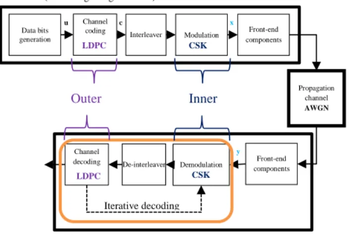
To sum up, this paper proposes to investigate a new GNSS signal design which is a Bit-Interleaved Coded Modulation (BICM) based on the serial concatenation of an outer LDPC code and an inner CSK modulation (see Figure 1).
Previous analysis of the CSK technique in a GNSS context has already been addressed in [1]. CSK-based signals for GNSS were proposed using the subframe 2 GPS L1C LDPC channel code. However, this code has been originally designed to be implemented with a BPSK modulation. It will be shown that better demodulation performance could be achieved for channel codes specifically optimized for a bit-interleaved CSK modulation using iterative decoding.
Therefore, this paper is mainly focused in optimizing the so-called LDPC channel code profile for a GNSS CSK-based signal and iterative decoding between the decoder and the demodulator.
Iterative decoding algorithm differs from classical sequential decoding algorithm by the output of the decoder which is fed back into the demodulator to perform iterative detection and decoding, which is by nature a suboptimal approach to provide an approximate Maximum A Posteriori (MAP) bit estimation.
To this end, the first step of this work consists in showing based on an asymptotic analysis that, whatever the outer channel code, an iterative decoding process will always
outperform the classical non-iterative decoding for a CSK-modulated GNSS signal in an AWGN propagation channel model. This analysis is based on an EXIT analysis. This analysis in an AWGN propagation channel has to be viewed as a preliminary study, which needs to be extended in the urban propagation channel context.
Secondly, an extension of the asymptotic optimization method as provided in [2] has been used to optimize the LDPC channel code profile.
Then, finite length LDPC codes with optimized profiles have been generated with the PEG algorithm [3].
Finally, simulation results are provided to compare the demodulation performance of the new designed GNSS signal with the current subframe 2 GPS L1C channel code, BPSK and CSK-modulated.
The paper is organized as follows. Section I describes the new designed GNSS signal based on LDPC channel codes and a CSK modulation. Section II gives the asymptotic analysis of the bit-interleaved CSK modulation showing that iterative decoding between the decoder and the CSK demodulator outperforms classical decoding for a CSK-modulated signal. Finally in section III, LDPC code profiles are optimized for a CSK-modulated signal iteratively decoded, and tested. The new designed GNSS signal demodulation performance is provided in an AWGN propagation channel and compared with the current GPS L1C subframe 2 demodulation performance.
I- Description of the New Designed GNSS Signal The purpose of this paper is to optimize LDPC code profiles for a GNSS CSK-modulated signal iteratively decoded (see Figure 1). The optimization will be done for an AWGN propagation channel in this paper.
Figure 1: GNSS Emission/Reception Chain Block Diagram for a CSK-Modulated and LDPC-Protected
Signal
This section introduces the LDPC channel code and the CSK modulation.
Outer
Iterative decoding
Reception (GNSS receiver processing) y x Emission (GNSS signals generation)
Data bits generation Channel coding Modulation Channel decoding Demodulation Propagation channel AWGN Front-end components Front-end components u c CSK LDPC CSK LDPC Interleaver De-interleaver Inner
1) LDPC Channel Codes
LDPC codes belong to the linear block codes family. These codes have already shown that they are good candidates, enable to approach the capacity of several channels including BICM schemes
[3]
.a. Linear Block Codes
Linear block codes encode data in blocks: an information sequence 𝒖 composed of 𝑘 information bits is encoded into a coded sequence 𝒄 composed of 𝑛 coded bits (as illustrated in Figure 2), adding redundancy in order to counteract the impact of errors introduced by the propagation channel.
Information word: 𝒖 = (𝑢0, 𝑢1, … , 𝑢𝑘−1) Coded word: 𝒄 = (𝑐0, 𝑐1, … , 𝑐𝑛−1) Figure 2: Classical Encoder Representation The coded word is the result of a generator matrix 𝐺 applied to the information word, as it is described in equation (1).
𝑐 = 𝑢𝐺 (1)
where:
𝐺 is the generator matrix with (𝑘 × 𝑛) dimensions. For any (𝑘 × 𝑛) matrix 𝐺 with 𝑘 linearly independent rows, it exists a ((𝑛 − 𝑘) × 𝑛) matrix 𝐻 with (𝑛 − 𝑘) linearly independent rows such that any vector in the row space of 𝐺 is orthogonal to the rows of 𝐻, and any vector that is orthogonal to the rows of 𝐻 is in the row space of 𝐺. The linear code 𝐶 can thus be generated by another way, thanks to the parity-check matrix 𝐻
[4]
if this parity-check matrix has the required structure.A vector 𝑐 is a codeword in the code 𝐶 generated by 𝐺 if and only if
[4]
:𝑐𝐻𝑇 = 0 (2)
where:
𝐻 is the parity check matrix with ((𝑛 − 𝑘) × 𝑛) dimensions, noted as:
𝐻 = (
ℎ11 … ℎ1𝑛
… ℎ𝑖𝑗 …
ℎ(𝑛−𝑘)1 … ℎ(𝑛−𝑘)𝑛 )
The resulting equations (the coded word multiplied by each 𝐻 row equal to zero) are called the parity check equations and completely specifies the code 𝐶
[4]
. The parity check matrix is obtained from the generator matrix by:𝐺𝐻𝑇= 0 (3)
b. LDPC Codes Definition
Only binary LDPC codes will be considered in this paper, although LDPC codes can be generalized to non-binary alphabets
[5]
.A LDPC code is a linear block code defined by the null space of an ((𝑛 − 𝑘) × 𝑛) parity-check matrix H that has a low density of 1s
[5]
.Thus a LDPC code can be defined as follows:
The null space of an ((𝑛 − 𝑘) × 𝑛) parity-check matrix H is defined by
[5]
:𝐶 = {𝑐 ∈ 𝐺𝐹(2)×𝑛⁄𝑐𝐻𝑇= 0} (4) where:
𝐶 is the null space of 𝐻,
𝑐 is the codeword vector,
𝐺𝐹(2) is the Galois field of two elements (for non-binary LDPC codes, this field is extended to 𝐺𝐹(𝑞), where 𝑞 is a power of a prime
[5]
). A ((𝑛 − 𝑘) × 𝑛) parity-check matrix 𝐻 that has alow density of 1s is defined by
[6]
:𝑛𝑢𝑚𝑏𝑒𝑟 𝑜𝑓 𝑛𝑜𝑛 𝑛𝑢𝑙𝑙 𝑒𝑙𝑒𝑚𝑒𝑛𝑡𝑠 𝑜𝑓 𝐻
(𝑛 − 𝑘) ∗ 𝑛 𝑛→∞→ 0 (5)
c. LDPC Codes Graphical Representation: Tanner Graph
A LDPC code can be represented by a Tanner graph
[5]
, which is based on the parity-check matrix H. A Tanner graph is a bipartite graph, which means a graph whose nodes may be separated into two types: The Variables Nodes (VN) and The Check Nodes (CN).
The Check Nodes correspond to the parity check equations resulting from equation (2), there are thus as many CNs as parity check equations: (𝑛 − 𝑘). Whereas the Variable Nodes correspond to the coded bits, its number being thus equal to n
[5]
. Thus, the CNs can be considered as Single Parity Check (SPC) codes and the VNs as repetition (REP) codes[5]
.(𝑛 𝑏𝑖𝑡𝑠) 𝒄 (𝑘 𝑏𝑖𝑡𝑠)
𝒖
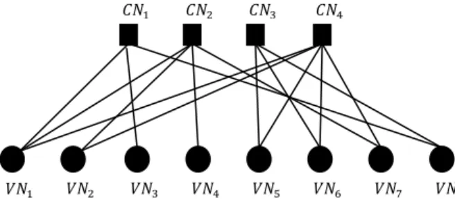
The Tanner graph of a code is drawn as follows: the Check Nodes CNi are connected to Variable Nodes VNj
with an edge whenever element ℎ𝑖𝑗 in the parity check matrix H is equal to 1.
For example, if the parity check matrix 𝐻 is equal to: 𝐻 = ( 1 1 0 1 0 1 0 1 1 0 0 0 0 1 0 0 0 0 1 1 0 0 1 1 0 1 0 1 1 0 1 0 ) (6)
the Tanner graph will be represented in this way:
Figure 3: Tanner Graph Associated to the H Matrix Example
A Tanner graph allows to completely represent a code and it aids in the description of the decoding algorithm [5].
d. LDPC Decoding
The Maximum Likelihood (ML) decoding [5] is too complex in this case, so another algorithm is implemented: the Sum-Product Algorithm (SPA) proposed by Gallager in 1962 [7]. There are two types of such algorithms based on hard or soft decision. The soft decision decoding is more efficient [7] that is why it has been chosen in this work, by the use of Log Likelihood Ratios (LLRs). Soft-decision decoding of LDPC codes is based on an iterative process: the Belief Propagation (BP) algorithm [7]. It consists on the updating of messages circulating on the branches of the Tanner graph, the information of the received bits (Variable Nodes) being refined after each iteration.
The BP LDPC decoding is detailed step-by-step in [8].
e. LDPC Codes Related Definitions Some definitions are given below [5]:
Structured and non-structured codes:
LDPC codes can be divided into two classes: The structured codes where the associated 𝐻 matrix is built following some constraints, and the non-structured codes where 𝐻 is built randomly.
Waterfall region and error-rate floor region:
LDPC codes error rate curve (see Figure 4) is divided into two regions: the waterfall region just before the slope transition, and the error-rate floor region.
Figure 4: Error Rate Curve Specificity for LDPC Codes
Cycle:
A cycle is a closed path which comes from and returns to the same node in a Tanner graph.
Girth:
The girth of a graph is defined as the length of its shortest cycle.
Node degree:
Number of edges connected to a node (equal to 3 for 𝑉𝑁1 in Figure 3 for example).
Regular code:
A code is said regular when the number of 1s per column and the number of 1s per row in H, are constants. It means that each node has the same degree.
Irregular code:
A code is said irregular when the number of 1s per column or per row in H, is not constant. The code represented by the Tanner graph of Figure 3 is for example irregular.
Degree-distribution polynomials:
For irregular codes, the node degrees being not constant, degree-distribution polynomials are denoted by 𝜆(𝑋) for VNs and 𝜌(𝑋) for CNs, defined by [5]:
{𝜆(𝑋) = ∑ 𝜆𝑖𝑋 𝑖−1 𝑑𝑣 𝑚𝑎𝑥 𝑖=2 𝜌(𝑋) = ∑𝑑𝑗=2𝑐 𝑚𝑎𝑥𝜌𝑗𝑋𝑗−1 (7) where:
𝑑𝑣 𝑚𝑎𝑥 and 𝑑𝑐 𝑚𝑎𝑥 being respectively the maximum VN and CN degrees,
0.4 0.5 0.6 0.7 0.8 0.9 1 1.1 1.2 1.3 1.4 10-4 10-3 10-2 10-1 100
Signal to Noise Ratio (SNR) in dB
E rr o r R a te 𝐶𝑁1 𝑉𝑁1 𝑉𝑁2 𝑉𝑁3 𝑉𝑁4 𝑉𝑁5 𝑉𝑁6 𝑉𝑁7 𝑉𝑁8 𝐶𝑁2 𝐶𝑁3 𝐶𝑁4
𝜆𝑖=𝑛𝑢𝑚𝑏𝑒𝑟 𝑜𝑓 𝑒𝑑𝑔𝑒𝑠 𝑐𝑜𝑛𝑛𝑒𝑐𝑡𝑒𝑑 𝑡𝑜 𝑡ℎ𝑒 𝑉𝑁𝑠 𝑜𝑓𝑑𝑒𝑔𝑟𝑒𝑒 𝑖 𝑛𝑢𝑚𝑏𝑒𝑟 𝑡𝑜𝑡𝑎𝑙 𝑜𝑓 𝑒𝑑𝑔𝑒𝑠 is the fraction of all edges connected to degree-d VNs,
𝜌𝑗=𝑛𝑢𝑚𝑏𝑒𝑟 𝑜𝑓 𝑒𝑑𝑔𝑒𝑠 𝑐𝑜𝑛𝑛𝑒𝑐𝑡𝑒𝑑 𝑡𝑜 𝑡ℎ𝑒 𝐶𝑁𝑠 𝑜𝑓𝑑𝑒𝑔𝑟𝑒𝑒 𝑗 𝑛𝑢𝑚𝑏𝑒𝑟 𝑡𝑜𝑡𝑎𝑙 𝑜𝑓 𝑒𝑑𝑔𝑒𝑠 is the fraction of all edges connected to degree-d CNs.
Short cycles degrade the performance of the BP decoding [5].
Irregular LDPC codes allow to closely approach capacity limits [5]. The GPS L1C channel code is an irregular (1200, 600) LDPC code for the subframe 2 and an (578, 274) irregular LDPC code for the subframe 3 [9].
Degree-distribution polynomials will be used in section III for the LDPC code design.
2) CSK Modulation
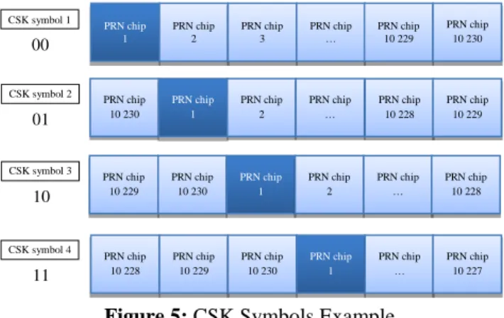
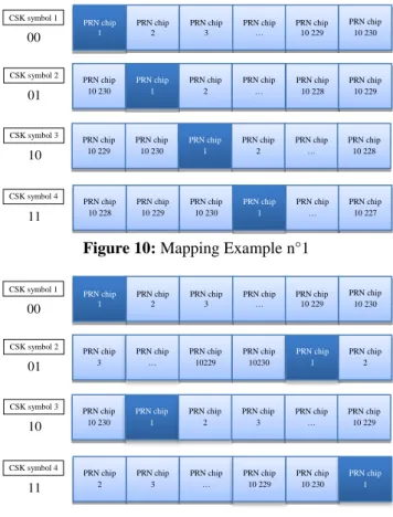
The Code Shift Keying (CSK) modulation is a 𝑀-ary orthogonal modulation, since 𝑀 orthogonal waveforms or symbols are used. Each symbol corresponds to the same PRN sequence, but circularly shifted [10]. Figure 5 shows CSK symbols example for 𝑀 = 4 with a PRN sequence length equal to 10230 chips. Since 𝑀 = 4, the number of bits per symbol, 𝑄, is equal to 2. In this case the mapping (the way to associate a waveform to a CSK symbol) is made considering consecutive shifts, but this can be different.
Figure 5: CSK Symbols Example
A shifted version 𝑐𝑥(𝑡) of the fundamental PRN sequence 𝑐𝑓𝑢𝑛𝑑(𝑡) can thus been written as shown in equation (8), for 𝑥 = 0, … , 𝑀 − 1 [11]:
𝑐𝑥(𝑡) = 𝑐𝑓𝑢𝑛𝑑(𝑚𝑜𝑑[𝑡 − 𝑚𝑥𝑇𝐶, 𝑁𝑇𝐶]) (8) where:
𝑚𝑜𝑑(𝑥, 𝑦) is the modulus operation of 𝑦 over 𝑥,
𝑚𝑥 is the integer number corresponding to the shift of the x-th symbol,
𝑇𝐶 is the PRN sequence chip period,
𝑁 is the number of chips in the PRN sequence (M is not necessarily equal to N).
According to equation (8) and document [8] considerations, the equivalent low-pass received waveform complex envelope can thus be written as:
𝑟(𝑡) = 𝐴 𝑎𝑐ℎ𝑎𝑛𝑛𝑒𝑙(𝑡)𝑒𝑗𝜑𝑐ℎ𝑎𝑛𝑛𝑒𝑙(𝑡) 𝑐𝑥(𝑡) + 𝑛(𝑡) (9) where:
𝐴 is the emitted signal amplitude,
𝑎𝑐ℎ𝑎𝑛𝑛𝑒𝑙(𝑡)𝑒𝑗𝜑𝑐ℎ𝑎𝑛𝑛𝑒𝑙(𝑡) is the propagation channel complex envelope,
𝑐𝑥(𝑡) is the emitted shifted version of the fondamental PRN sequence (the CSK waveform),
𝑛(𝑡) is the AWGN.
In order to determine which shifted version has been emitted, a matched filter is used for each symbol of modulation alphabet [12]. Each matched filter output is thus the result of the correlation between the received waveform and one of the shifted versions of the fundamental PRN sequence [11]. The symbol 𝑦 identified by the largest matched filter output 𝑐𝑜𝑟𝑟𝑖 is chosen as the transmitted symbol. This process results in a matched filters bank, which can be implemented using Fast Fourier Transform (FFT) and Inverse Fourier Transform (IFFT) blocks, since it completes efficiently the correlation process in the frequency domain [11]. The resulting operation is thus written as:
𝐶𝑂𝑅𝑅 = 𝐼𝐹𝐹𝑇 (𝐹𝐹𝑇(𝑟[𝑘]) × 𝐹𝐹𝑇(𝑐𝑓𝑢𝑛𝑑[−𝑘])) (10) With 𝐶𝑂𝑅𝑅 = [𝑐𝑜𝑟𝑟1, 𝑐𝑜𝑟𝑟2, … , 𝑐𝑜𝑟𝑟𝑀].
Finally, the CSK demodulator can be represented by Figure 6 [11]:
Figure 6: CSK FFT-Based Demodulator Representation The CSK modulation is able to transmit several bits using one symbol (corresponding to one PRN sequence duration) contrary to the BPSK modulation which imposes than one bit matches one symbol, corresponding to one PRN sequence duration. The CSK thus allows high and adaptive bit rates.
II- Iterative Decoding Versus Classical Decoding for a CSK-Modulated Signal
1) Symbol Based MAP Demodulation for CSK-Modulated Signals 00 PRN chip 1 PRN chip 2 PRN chip 3 PRN chip … PRN chip 10 229 PRN chip 10 230 PRN chip 1 PRN chip 2 PRN chip … PRN chip 10 228 CSK symbol 1 PRN chip 10 230 PRN chip 10 229 PRN chip 10 229 PRN chip 10 230 PRN chip 1 PRN chip 2 PRN chip … PRN chip 10 228 PRN chip 10 228 PRN chip 10 229 PRN chip 10 230 PRN chip 1 PRN chip … PRN chip 10 227 01 CSK symbol 2 10 CSK symbol 3 11 CSK symbol 4 𝐶𝑂𝑅𝑅(𝑓) 𝐶𝑓𝑢𝑛𝑑∗ (𝑓) 𝑅(𝑓) 𝑟[𝑘] 𝑐𝑓𝑢𝑛𝑑∗ [−𝑘] Discrete Fourier Transform Discrete Fourier Transform Discrete Inverse Fourier Transform 𝑐𝑜𝑟𝑟1 𝑐𝑜𝑟𝑟2 𝑐𝑜𝑟𝑟𝑀 …
During the decoding process, messages are exchanged between the CSK demodulator and the LDPC decoder which can be seen as a BICM [13] (see Figure 1 in orange). These exchanged messages are typically Log Likelihood Ratios (LLR) based on A Posteriori Probability (APP) [14][15] (see [8] for details).
The APP LLR expression is based on both observation samples and channel parameters. Since the probability of each bit 𝑏𝑥𝑞 of the emitted CSK symbol 𝑥 knowing the received CSK symbol 𝑦 depends on the considered modulation, the 𝐿𝐿𝑅𝐴𝑃𝑃 expression for a CSK-modulated signal will be different from a BPSK-modulated signal. It is thus necessary to derive the 𝐿𝐿𝑅𝐴𝑃𝑃 function for a CSK-modulated signal.
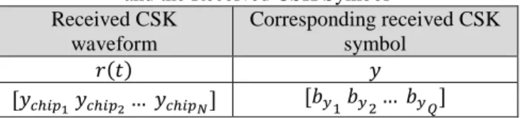
Table 1: Mapping Between the Emitted CSK Waveform and the Emitted CSK Symbol
Emitted CSK waveform Corresponding emitted CSK symbol 𝑐𝑥(𝑡) 𝑥 [𝑥𝑐ℎ𝑖𝑝1 𝑥𝑐ℎ𝑖𝑝2… 𝑥𝑐ℎ𝑖𝑝𝑁] [𝑏𝑥1 𝑏𝑥2… 𝑏𝑥𝑄] Table 2: Mapping Between the Received CSK Waveform
and the Received CSK Symbol Received CSK waveform Corresponding received CSK symbol 𝑟(𝑡) 𝑦 [𝑦𝑐ℎ𝑖𝑝1 𝑦𝑐ℎ𝑖𝑝2… 𝑦𝑐ℎ𝑖𝑝𝑁] [𝑏𝑦1 𝑏𝑦2… 𝑏𝑦𝑄]
In this paper, the following assumptions have been made:
The APP LLR mathematical expression is derived considering an AWGN propagation channel model, The carrier phase tracking error is equal to 0,
The knowledge of the beginning of the transmitted sequence is assumed.
The 𝐿𝐿𝑅𝐴𝑃𝑃 expression corresponding to a GNSS CSK-modulated signal in an AWGN propagation channel is derived as follows. It is computed for each bit q of the emitted CSK symbol:
𝐿𝐿𝑅𝐴𝑃𝑃𝑞−𝐶𝑆𝐾 = 𝑙𝑜𝑔 (
𝑝 (𝑏𝑥𝑞= 1| 𝑦 )
𝑝 (𝑏𝑥𝑞 = −1| 𝑦 )) (11) where:
𝑏𝑥𝑞 is the q-th bit of the emitted CSK symbol 𝑥,
𝑦 is the received CSK symbol (see Equation (10)),
𝑝 (𝑏𝑥𝑞 = 1| 𝑦) is the APP that the q-th bit of the emitted CSK symbol 𝑥 equal to 1 has been transmitted, knowing the received symbol 𝑦
After derivation (fully detailed in [8]), the 𝐿𝐿𝑅𝐴𝑃𝑃−𝐶𝑆𝐾 expression corresponding to a GNSS CSK-modulated signal in an AWGN propagation channel is written by:
𝐿𝐿𝑅𝐴𝑃𝑃𝑞−𝐶𝑆𝐾= 𝑙𝑜𝑔 ( ∑ [𝑒 1 𝜎𝑏2∑ (𝑦𝑐ℎ𝑖𝑝𝑖𝑥𝑐ℎ𝑖𝑝𝑖) 𝑁 𝑖=1 ∏𝑗≠𝑞𝑝 (𝑏𝑥𝑗)] 𝐴𝑙𝑙 𝐶𝑆𝐾 𝑠𝑦𝑚𝑏𝑜𝑙𝑠 𝑤ℎ𝑖𝑐ℎ 𝑏𝑥𝑞=1 ∑ [𝑒 1 𝜎𝑏2 ∑𝑁(𝑦𝑐ℎ𝑖𝑝𝑖𝑥𝑐ℎ𝑖𝑝𝑖) 𝑖=1 ∏ 𝑝 (𝑏𝑥𝑗) 𝑗≠𝑞 ] 𝐴𝑙𝑙 𝐶𝑆𝐾 𝑠𝑦𝑚𝑏𝑜𝑙𝑠 𝑤ℎ𝑖𝑐ℎ 𝑏𝑥𝑞=−1 ) + 𝑙𝑜𝑔 (𝑝 (𝑏𝑥𝑞= 1) 𝑝 (𝑏𝑥𝑞= −1)) (12) where: ∑𝑁 (𝑦𝑐ℎ𝑖𝑝𝑖𝑥𝑐ℎ𝑖𝑝𝑖) 𝑖=1 = 𝑐𝑜𝑟𝑟(𝑐𝑥, 𝑟) is the correlation operation between the emitted PRN sequence and the received signal. Since the code delay is assumed to be perfectly estimated, this value is equal to 1 if the received PRN sequence (corresponding to a CSK symbol) is the same than the emitted PRN sequence (corresponding in this case to the same CSK symbol), and this value is equal to 0 otherwise. In fact, a correlator filter bank is used at the GNSS reception level: one correlator for one CSK symbol, to determine which CSK symbol has been received. From equation (12), the 𝐿𝐿𝑅𝐴𝑃𝑃𝑞−𝐶𝑆𝐾 can be divided into
two components, as it is done into equation (13):
The extrinsic part 𝐿𝐿𝑅𝐸𝑞−𝐶𝑆𝐾 : the idea is that a node does not pass to a neighboring node any information that the neighboring node already has [14]. This is the information that will be fed to the Input Soft-Output (SISO) BP LDPC decoder.
The a priori part 𝐿𝐿𝑅𝐴𝑞−𝐶𝑆𝐾which represents the a
priori information concerning the bit 𝑞 [16]. 𝐿𝐿𝑅𝐴𝑃𝑃𝑞−𝐶𝑆𝐾 = 𝐿𝐿𝑅𝐸𝑞−𝐶𝑆𝐾+ 𝐿𝐿𝑅𝐴𝑞−𝐶𝑆𝐾 (13)
In fact, the LLR based on a posteriori probability 𝐿𝐿𝑅𝐴𝑃𝑃𝑞−𝐶𝑆𝐾 is computed by the demodulator (as demodulator output) according to the channel observations 𝑦𝑞 and the a priori CSK LLRs: 𝐿𝐿𝑅𝐴𝑞−𝐶𝑆𝐾=
𝑙𝑜𝑔 (𝑝(𝑏𝑥𝑞=1)
𝑝(𝑏𝑥𝑞=−1)) for each bit 𝑞 (see Figure 7). Then, the extrinsic CSK LLR is computed and sent to the LDPC decoder.
Figure 7: CSK Demodulator Soft Inputs and Outputs
2) Difference Between Classical and Iterative Decoding
From the detection function 𝐿𝐿𝑅𝐴𝑃𝑃−𝐶𝑆𝐾 considering a CSK demodulator in an AWGN propagation channel, the decoding process between the demodulator and the decoder can be made through two different methods [11]:
The classical CSK decoding method, The iterative decoding method.
The difference between these two decoding methods lies in the exchanges between the CSK demodulator and the LDPC decoder. In iterative decoding the LDPC decoder provides feedback to the CSK demodulator (see Figure 9), whereas in classical decoding the exchanges are only supported by a downlink stream (see Figure 8).
a. Classical Decoding
In classical decoding, the CSK demodulator is fed by channel observations y and a priori LLRs (see Figure 8) which are computed considering equiprobable bits.
Figure 8: CSK Demodulator and LDPC Decoder Combination, Linked by LLR Exchanged Messages, for
the Classical Decoding Method
In this context where binary data is used, these a priori LLRs are thus equal to:
𝐿𝐿𝑅𝐴𝑞−𝐶𝑆𝐾 = 𝑙𝑜𝑔 (
𝑝 (𝑏𝑥𝑞 = 1)
𝑝 (𝑏𝑥𝑞= −1)) = 0 (14) The extrinsic LLRs are then computed by the demodulator according to equations (12) and (13).
The LDPC decoder initiates then its VNs with these CSK extrinsic LLRs, and the BP decoding is performed as described in [8]. There is no iterative decoding between the soft CSK demodulator and the LDPC decoder.
b. Iterative Decoding
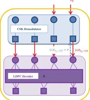
In iterative decoding, the CSK demodulator is fed by channel observations y and a priori LLRs which are computed considering equiprobable bits at the first iteration. Then, the CSK extrinsic LLRs are computed by the CSK demodulator according to equations (12) and (13). These values are sent to the LDPC decoder and one BP decoding iteration is performed (see [8]). The LDPC extrinsic LLRs resulting of this LDPC decoding process are then sent back to the CSK demodulator. They are used as CSK a priori LLRs at the CSK demodulator inputs. This is the iterative decoding principle as given in Figure 9.
Figure 9: CSK Demodulator and LDPC Decoder Combination, Linked by LLR Exchanged Messages, for
the Iterative Decoding Method CSK Demodulator 𝑳𝑳𝑹𝑬𝒒−𝑪𝑺𝑲 𝑳𝑳𝑹𝑨𝒒−𝑪𝑺𝑲 𝒚𝒒 𝐿𝐿𝑅𝐴𝑞−𝐶𝑆𝐾= 0 𝒚𝒒 𝐿𝐿𝑅𝐸𝑞−𝐶𝑆𝐾 Π CSK Demodulator LDPC Decoder 𝑳𝑳𝑹𝑬𝒒−𝑳𝑫𝑷𝑪 = 𝑳𝑳𝑹𝑨𝒒−𝑪𝑺𝑲 𝒚𝒒 𝑳𝑳𝑹𝑬𝒒−𝑪𝑺𝑲 Π CSK Demodulator LDPC Decoder
The preliminary step of these new signal design investigations consists in determining if iterative decoding between the demodulator and the decoder provides better demodulation performance than non-iterative decoding.
3) EXIT Chart for a CSK-Modulated Signal In this section, the potential benefit of iterative decoding between the demodulator and the decoder is analyzed for a CSK-modulated GNSS signal in an AWGN propagation channel. In order to determine if iterative decoding provides better performance than non-iterative decoding in the case of a CSK-modulated GNSS signal, the EXtrinsic-Information-Transfer (EXIT) chart is used.
a. EXIT Chart Definition
The EXIT chart is a graphical tool developed by Ten Brink [17] in the late 1990s which consists in representing the extrinsic information at the output of a SISO block (demodulator or decoder), as a function of the a priori information at the input of the same Soft Input Soft Output (SISO) block.
In EXIT charts, the information (extrinsic or a priori) which is considered is the mutual information 𝐼(𝑌; 𝑍) [15]. It could be another statistic as the LLR mean or the SNR for example [18], but the mutual information is considered as the most accurate and the most robust statistic [19].
An EXIT chart consists thus on plotting the output metric of interest, the extrinsic mutual information 𝐼𝐸, as a function of the input metric of interest, the a priori mutual information 𝐼𝐴.
The a priori information 𝐼𝐴 corresponds to the mutual information between the emitted coded bits 𝑏𝑥 and the a priori messages 𝐿𝐿𝑅𝐴 [15]:
𝐼𝐴= 𝐼(𝐿𝐿𝑅𝐴; 𝑏𝑥) = 𝐻(𝑏𝑥) − 𝐻(𝑏𝑥⁄𝐿𝐿𝑅𝐴) (15) Whereas the extrinsic information 𝐼𝐸 corresponds to the mutual information between the emitted coded bits 𝑏𝑥 and the extrinsic messages 𝐿𝐿𝑅𝐸 [15]:
𝐼𝐸= 𝐼(𝐿𝐿𝑅𝐸; 𝑏𝑥) = 𝐻(𝑏𝑥) − 𝐻(𝑏𝑥⁄𝐿𝐿𝑅𝐸) (16) If the extrinsic information quantity increases with the a priori information quantity (i.e. the EXIT chart for the given signal to noise ratio is non-flat), it means that an iterative decoding will improve the performance. Indeed, if bringing more a priori information to the demodulator involves a higher extrinsic information quantity (provided exclusively by the demodulator structure) at its output, it means that the demodulator capacities will be better if the a priori information is increased by the decoder, which is done by iterative decoding between the demodulator and the decoder.
The aim of this section consists thus in studying the EXIT charts of the CSK demodulator to assess its performance under iterative decoding.
b. Generated EXIT Charts
EXIT charts corresponding to a CSK-modulated signal in an AWGN propagation channel model, with CSK symbols constituted of 2 bits, 6 bits and 10 bits have been generated. In that goal, 𝐼𝐸−𝐶𝑆𝐾 has been computed as a function of 𝐼𝐴−𝐶𝑆𝐾. The full computation of 𝐼𝐸 as a function of 𝐼𝐴 is detailed in [8]. A random mapping (which associates the shift applied to the PRN sequence to the CSK symbol, see examples in Figure 10 and Figure 11) is used.
Figure 10: Mapping Example n°1
Figure 11: Mapping Example n°2
Several plots are presented, corresponding to different values of energy per symbol to noise density ratio Es/N0.
00 PRN chip 1 PRN chip 2 PRN chip 3 PRN chip … PRN chip 10 229 PRN chip 10 230 PRN chip 1 PRN chip 2 PRN chip … PRN chip 10 228 CSK symbol 1 PRN chip 10 230 PRN chip 10 229 PRN chip 10 229 PRN chip 10 230 PRN chip 1 PRN chip 2 PRN chip … PRN chip 10 228 PRN chip 10 228 PRN chip 10 229 PRN chip 10 230 PRN chip 1 PRN chip … PRN chip 10 227 01 CSK symbol 2 10 CSK symbol 3 11 CSK symbol 4 00 PRN chip 1 PRN chip 2 PRN chip 3 PRN chip … PRN chip 10 229 PRN chip 3 PRN chip … PRN chip 10229 PRN chip 10230 PRN chip 1 CSK symbol 1 PRN chip 10 230 PRN chip 2 PRN chip 10 230 PRN chip 1 PRN chip 2 PRN chip 3 PRN chip … PRN chip 10 229 PRN chip 2 PRN chip 3 PRN chip … PRN chip 10 229 PRN chip 10 230 PRN chip 1 01 CSK symbol 2 10 CSK symbol 3 11 CSK symbol 4
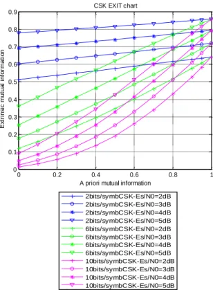
Figure 12: CSK EXIT Charts for Different Numbers of Bits per CSK Symbols
This figure clearly shows that a higher value of a priori information at the CSK demodulator input provides a higher value of extrinsic information at the CSK demodulator output. An iterative decoding will thus significantly improve the CSK demodulator performance. Moreover, the curves slopes depend on the number of bits per CSK symbol. The more the number of bits per CSK symbol is, the more the EXIT chart curve slope is important, stressing the need for an iterative decoding in this case, compared with a few number of bits per CSK symbol.
Finally, the EXIT chart function T is extracted from these EXIT chart plots (see equation (17)), to be used in the LPDC asymptotic and code optimization process, as it is detailed in section III, since analytic expressions of T are not available. In practice, T is approximated using a polynomial curve fitting and is formally written as:
𝐼𝐸= 𝑇[𝐼𝐴] (17)
c. Properties about the Area under the EXIT Curve Properties about the area under the EXIT curves have been set out in [19] for the binary erasure channel and generalized in [20], leading to the general acknowledgement that for serial concatenated coders (as it is the case here if we consider the LDPC coder as the outer coder and the CSK modulator as the inner coder), the area under the inner decoder EXIT curve can be linked to the maximum achievable channel code rate [19][20][21]. In our case, this statement can be written as:
𝐴𝐶𝑆𝐾= ∫ 𝑇𝐶𝑆𝐾(𝑖)𝑑𝑖 1 0 ≈ 𝑅0 (18) where:
𝐴𝐶𝑆𝐾 is the area under the EXIT chart of the CSK demodulator,
𝑇𝐶𝑆𝐾 is the EXIT chart function associated with the inner decoder (here the CSK demodulator, represented in Figure 12),
𝑅0 is the maximum achievable channel code rate. Thus, the maximum channel code rate 𝑅0 at which reliable communication is possible for a given Es/N0 can
be efficiently estimated: it corresponds to the area under the CSK demodulator EXIT curve. This interesting property will be used in the LDPC code optimization process described and implemented in the next section.
For example, maximum achievable rates as a function of Es/N0, for classical decoding (in blue line) and iterative
decoding (in red line) between the decoder and the demodulator have been compared, for 10 bits per CSK symbol in Figure 13.
Figure 13: Comparison Between the Maximum Achievable Code Rate 𝑅0 with Iterative and Non-Iterative
Decoding, for a CSK Symbol Composed of 10 bits
Figure 13 shows that for a signal modulated with a CSK with 10 bits per CSK symbol, iterative decoding completely outperforms non-iterative decoding, especially for low Es/N0. For example at Es/N0 equal to 2 dB, a
reliable communication with non-iterative decoding is achievable for a maximum code rate of 0.01, meaning that at least 100 coded bits are necessary to encode 1 information bit. In comparison, with iterative decoding this maximum code rate is equal to 0.25, implying at least 4 coded bits for 1 information bit. The iterative decoding gain with a CSK-modulated signal appears as very efficient compared to the non-iterative case.
2 3 4 5 6 7 8 9 10 11 0 0.1 0.2 0.3 0.4 0.5 0.6 0.7 0.8 0.9 1 Es/N0 [dB] M a xi m u m a ch ie va b le r a te R 0
Area under CSK demodulator EXIT charts with 10 bits per CSK symbol Iterative decoding
Non iterative decoding
0 0.2 0.4 0.6 0.8 1 0 0.1 0.2 0.3 0.4 0.5 0.6 0.7 0.8 0.9
A priori mutual information
E xt ri n si c m u tu a l in fo rm a ti o n CSK EXIT chart 2bits/symbCSK-Es/N0=2dB 2bits/symbCSK-Es/N0=3dB 2bits/symbCSK-Es/N0=4dB 2bits/symbCSK-Es/N0=5dB 6bits/symbCSK-Es/N0=2dB 6bits/symbCSK-Es/N0=3dB 6bits/symbCSK-Es/N0=4dB 6bits/symbCSK-Es/N0=5dB 10bits/symbCSK-Es/N0=2dB 10bits/symbCSK-Es/N0=3dB 10bits/symbCSK-Es/N0=4dB 10bits/symbCSK-Es/N0=5dB 0 0.2 0.4 0.6 0.8 1 0 0.1 0.2 0.3 0.4 0.5 0.6 0.7 0.8 0.9
A priori mutual information
E xt ri n si c m u tu al i nf o rm a ti on CSK EXIT chart 2bits/symbCSK-Es/N0=2dB 2bits/symbCSK-Es/N0=3dB 2bits/symbCSK-Es/N0=4dB 2bits/symbCSK-Es/N0=5dB 6bits/symbCSK-Es/N0=2dB 6bits/symbCSK-Es/N0=3dB 6bits/symbCSK-Es/N0=4dB 6bits/symbCSK-Es/N0=5dB 10bits/symbCSK-Es/N0=2dB 10bits/symbCSK-Es/N0=3dB 10bits/symbCSK-Es/N0=4dB 10bits/symbCSK-Es/N0=5dB
maximum code rate = 0.25 4 coded bits for 1
information bit
maximum code rate = 0.01 100 coded bits to encode
III- LDPC Code Profile Optimization for a CSK-Modulated Signal
The LDPC channel code design has been optimized for a GNSS CSK-modulated signal, in an AWGN channel, for iterative decoding between the demodulator and the decoder, using the asymptotic analysis.
1) Asymptotic Analysis to Obtain Optimized LDPC Code Parameters
In this section we derive the asymptotic analysis [22] for the LDPC channel code optimization under iterative decoding. This method is based on the demodulator EXIT chart function (determined in section II for a CSK modulation) and on the updating equations of the exchanged LLR messages between the demodulator and the decoder (fully derived in [8]). Under appropriate assumptions, the method consists in solving a linear programming optimization problem (presented in [8]), whose cost function is to maximize the channel code rate, which leads to good degree distributions (see section I) for the LDPC channel code parameters. In other words, to optimize the code profile 𝜆(𝑋) for fixed Es/N0 and fixed
𝜌(𝑋), one strategy consists in maximizing the code rate given by : 𝑅 = 1 −∑ 𝜌𝑗 𝑗 ⁄ 𝑑𝑐 𝑗=2 ∑ 𝜆𝑖 𝑖 ⁄ 𝑑𝑣 𝑖=2 (19)
This asymptotic analysis has been conducted (in [8]) leading to the optimized LDPC code edges profile for a CSK-modulated signal (since we have used EXIT charts for a CSK-modulated signal) in an AWGN propagation channel model, under iterative decoding between the demodulator and the decoder, which has to be seen as the first step of a new GNSS signal design.
2) Generation of Finite Length LDPC Code Matrices According to the asymptotic analysis and resulting optimized LDPC code edges profile, finite length 𝐻 matrices have been generated with the Progressive-Edge-Growth (PEG) algorithm [23]. In that sense, several configurations have been tested (see Table 3, Table 4 and Table 5), but with always the same information sequence length equal to 600 bits with a rate of ½, in order to be able to be compared with the GPS L1C subframe 2 signal (Table 4) demodulation performance. For a CSK-modulated signal, 2 bits (Table 4) and then 6 bits (Table 5) per symbol have been tested, with non-iterative or iterative decoding. For optimized LDPC codes, different maximum variable nodes degrees have been tested, and the number of degree 2 VNs have been limited or not, since a high number of degree 2 VNs increases the error floor level. Nevertheless, it allows an earlier waterfall. Thus, a trade-off needs to be found [24].
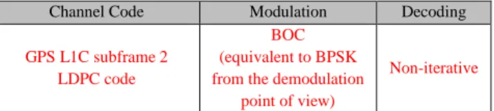
Table 3: Signal Corresponding to GPS L1C Subframe 2
Channel Code Modulation Decoding
GPS L1C subframe 2 LDPC code
BOC (equivalent to BPSK from the demodulation
point of view)
Non-iterative
Table 4: CSK Modulation with 2 bits per CSK Symbol
Channel Code Modulation Decoding
GPS L1C subframe 2 LDPC code CSK Non-iterative GPS L1C subframe 2 LDPC code CSK Iterative Optimized LDPC code 1 (max VNs degree = 15, constrained degree 2 VNs) CSK Iterative Optimized LDPC code 2 (max VNs degree = 10, constrained degree 2 VNs) CSK Iterative
Table 5: CSK Modulation with 6 bits per CSK Symbol
Channel Code Modulation Decoding
GPS L1C subframe 2 LDPC code CSK Iterative Optimized LDPC code 1 (max VNs degree = 15, constrained degree 2 VNs) CSK Iterative Optimized LDPC code 2 (max VNs degree = 15,
no-constrained degree 2 VNs)
CSK Iterative
3) Results: Demodulation Performance of the New Designed GNSS Signal
The new designed GNSS signals, CSK-modulated and protected by optimized LDPC channel codes have been tested and compared with the GPS L1C subframe 2 demodulation performance, in an AWGN propagation channel.
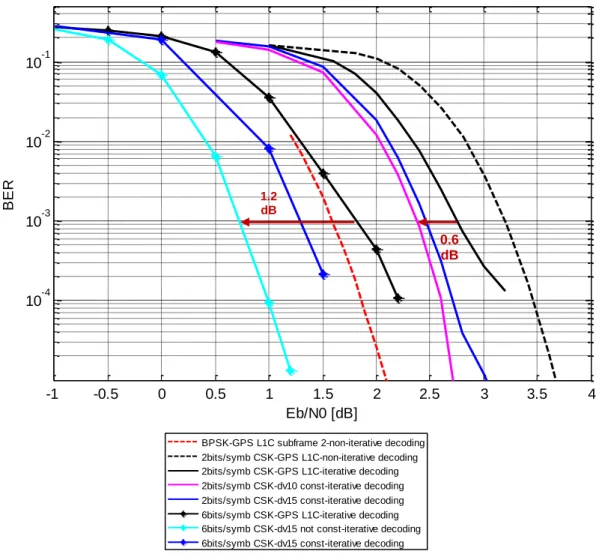
There, the aim is to quantify the demodulation gain only brought by the optimized LDPC channel codes, compared with those latest designed (subframe 2 GPS L1C). In that sense, the BER is plotted as a function of Eb/N0 to have
constant data rates, and we compare CSK-modulated signals, with 600 information sequence length and protected by rate ½ LDPC codes, with an iterative decoding between the CSK demodulator and the LDPC decoder. As shown in , for 2 bits per CSK symbol, the first proposed optimized code (in blue) outperforms the GPS L1C subframe 2 LDPC code by about 0.5 dB. We can also show that better performance can be achieved considering lower maximum VN degrees enabling larger girth without penalizing two much the performance in the waterfall region. For the case of the 6 bits per CSK symbols, we have a maximum variable node degree of 15 and we compare two codes that have been designed with and without the degree 2 node constraint. As we can see there is a non-negligible penalty in the waterfall region
when constraining the degree 2 variable nodes. We can also notice that the best performing designed code
outperforms significantly the GPS L1C LDPC code under iterative decoding by about 1.2 dB at BER= 10-3.
Figure 14: Finite Length Results: BER According to Eb/N0 for 2 bits and 6 bits per CSK Symbol
CONCLUSION
The new designed signal, CSK-modulated and protected by an optimized LDPC channel code, addresses the initial objectives which were: to increase the GNSS signal data rate, as well as the GNSS signal availability. Indeed, it has been showed that the CSK modulation allows an increased data rate, and the associated LDPC channel code has been specially optimized for a CSK modulation, iterative decoding between the CSK demodulator and the LDPC decoder, and in an AWGN propagation channel. This optimization allowed us to achieve a demodulation gain between 0.6 to 1.2 dB, depending on the number of bits mapping the CSK symbol. Nevertheless, the work needs to be continued. This new signal must be tested in an urban propagation channel, to be compared with the
current GNSS signals. Moreover, the CSK mapping needs to be further investigated. And optimized LDPC code profiles can be further analyzed, considering for example the design of structured LDPC codes such as structured IRA (Irregular Repeat Accumulate) or protograph based constructions to enable efficient encoding and decoding. Then, since our investigations lead to cycles codes (no-constrained degree 2 VNs bringing better performance, and a high number of degree 2 VNs inducing cycles), extension to the non-binary case could be considered [25] and compared to existing approaches [26][27].
REFERENCES
[1] A. Garcia-Pena, D. Salos, O. Julien, L. Ries, and T. Grelier, “Analysis of the use of CSK for Future GNSS Signals,” Proc. 26th Int. Tech. Meet. Satell.
Div. Inst. Navig. ION GNSS 2013 Sept. 16 - 20 2013 Nashv. Conv. Cent. Nashv. Tenn. Nashv. TN,
-1 -0.5 0 0.5 1 1.5 2 2.5 3 3.5 4 10-4 10-3 10-2 10-1 Eb/N0 [dB] BER
6bits/symb CSK-dv15 const-iterative decoding
-1 -0.5 0 0.5 1 1.5 2 2.5 3 3.5 4 10-4 10-3 10-2 10-1 Eb/N0 [dB] BER
BPSK-GPS L1C subframe 2-non-iterative decoding 2bits/symb CSK-GPS L1C-non-iterative decoding 2bits/symb CSK-GPS L1C-iterative decoding 2bits/symb CSK-dv10 const-iterative decoding 2bits/symb CSK-dv15 const-iterative decoding 6bits/symb CSK-GPS L1C-iterative decoding 6bits/symb CSK-dv15 not const-iterative decoding 6bits/symb CSK-dv15 const-iterative decoding
0.6 dB 1.2
pp. 1461 – 1479.
[2] S. ten Brink, G. Kramer, and A. Ashikhmin, “Design of low-density parity-check codes for modulation and detection,” IEEE Trans. Commun., vol. 52, no. 4, pp. 670–678, Apr. 2004.
[3] W. Ryan and S. Lin, Channel Codes: Classical and
Modern. Cambridge University Press, 2009.
[4] S. L., Daniel J. Costello, Error Control Coding. Pearson Education India.
[5] W. Ryan and S. Lin, Channel Codes: Classical and
Modern, 1st ed. Cambridge University Press, 2009.
[6] Poulliat, “Codes LDPC.” Nov-2011.
[7] I. Bacic, K. Malaric, and Z. Petrunic, “A LDPC code/decode channel coding model based on sum-product algorithm realization via LabVIEW,” in
ICECom, 2010 Conference Proceedings, 2010, pp.
1–4.
[8] M. Roudier, “Analysis and Improvement of GNSS Navigation Message Demodulation Performance in Urban Environments,” PhD, Toulouse, INPT, 2015. [9] Dafesh, Vallés, Hsu, Sklar, Zapanta, and Cahn,
“Data Message Performance for the Future L1C GPS Signal,” presented at the Proceedings of the 20th International Technical Meeting of the Satellite Division of The Institute of Navigation (ION GNSS 2007) September 25 - 28, 2007 Fort Worth Convention Center Fort Worth, TX, pp. 2519 – 2528.
[10] A. Y.-C. Wong and V. C. M. Leung, “Code-phase-shift keying: a power and bandwidth efficient spread spectrum signaling technique for wireless local area network applications,” in IEEE 1997
Canadian Conference on Electrical and Computer Engineering, 1997. Engineering Innovation: Voyage of Discovery, 1997, vol. 2, pp. 478–481
vol.2.
[11] A. Garcia-Pena, P. Paimblanc, D. Salós, O. Julien, M.-L. Boucheret, T. Grelier, L. Ries, A. Garcia-Pena, P. Paimblanc, D. Salós, O. Julien, M.-L. Boucheret, T. Grelier, and L. Ries, “Investigation of CSK as a Candidate for Future GNSS Signals, Investigation of CSK as a Candidate for Future GNSS Signals,” presented at the EWGNSS 2013, 6th European Workshop on GNSS Signals and Signal Processing, EWGNSS 2013, 6th European Workshop on GNSS Signals and Signal Processing.
[12] J. G. Proakis and M. Salehi, Digital
communications. Boston: McGraw-Hill, 2008.
[13] G. Caire, G. Taricco, and E. Biglieri, “Bit-interleaved coded modulation,” IEEE Trans. Inf.
Theory, vol. 44, no. 3, pp. 927–946, May 1998.
[14] W. Ryan and S. Lin, Channel Codes: Classical and
Modern. Cambridge University Press, 2009.
[15] S. ten Brink, “Design of concatenated coding schemes based on iterative decoding convergence,” Shaker, Aachen, 2002.
[16] J. R. Barry and E. A. Lee, Digital Communication, Édition : 3rd ed. 2003. Boston: Kluwer Academic Publishers, 2003.
[17] S. Ten Brink, “Convergence of iterative decoding,”
Electron. Lett., vol. 35, no. 10, pp. 806–808, May
1999.
[18] M. Tüchler, S. T. Brink, and J. Hagenauer, “Measures for Tracing Convergence of Iterative Decoding Algorithms,” in in Proc. 4th IEEE/ITG
Conf. on Source and Channel Coding, 2002, pp.
53–60.
[19] A. Ashikhmin, G. Kramer, and S. ten Brink, “Extrinsic information transfer functions: model and erasure channel properties,” IEEE Trans. Inf.
Theory, vol. 50, no. 11, pp. 2657–2673, Nov. 2004.
[20] J. Hagenauer, “The EXIT Chart - Introduction to Extrinsic Information Transfer,” in in Iterative
Processing,” In Proc. 12th Europ. Signal Proc. Conf (EUSIPCO, 2004, pp. 1541–1548.
[21] A. G. i Fàbregas, A. Martinez, and G. Caire,
Bit-Interleaved Coded Modulation. Now Publishers
Inc, 2008.
[22] S. ten Brink, G. Kramer, and A. Ashikhmin, “Design of low-density parity-check codes for modulation and detection,” IEEE Trans. Commun., vol. 52, no. 4, pp. 670–678, Apr. 2004.
[23] X.-Y. Hu, E. Eleftheriou, and D.-M. Arnold, “Progressive edge-growth Tanner graphs,” in IEEE
Global Telecommunications Conference, 2001. GLOBECOM ’01, 2001, vol. 2, pp. 995–1001 vol.2.
[24] S. J. Johnson and S. R. Weller, “Constraining LDPC degree distributions for improved error floor performance,” IEEE Commun. Lett., vol. 10, no. 2, pp. 103–105, Feb. 2006.
[25] E. E. X. -Yu. Hu, “Binary representation of cycle Tanner-graph GF(2b) codes,” pp. 528 – 532 Vol.1, 2004.
[26] O. Abassi, L. Conde-Canencia, M. Mansour, and E. Boutillon, “Non-Binary Low-Density Parity-Check
coded Cyclic Code-Shift Keying,” in 2013 IEEE
Wireless Communications and Networking Conference (WCNC), 2013, pp. 3890–3894.
[27] O. Abassi, L. Conde-Canencia, M. Mansour, and E. Boutillon, “Non-binary coded CCSK and
Frequency-Domain Equalization with simplified LLR generation,” in 2013 IEEE 24th International
Symposium on Personal Indoor and Mobile Radio Communications (PIMRC), 2013, pp. 1478–1483.