READ THESE TERMS AND CONDITIONS CAREFULLY BEFORE USING THIS WEBSITE.
https://nrc-publications.canada.ca/eng/copyright
Vous avez des questions? Nous pouvons vous aider. Pour communiquer directement avec un auteur, consultez la
première page de la revue dans laquelle son article a été publié afin de trouver ses coordonnées. Si vous n’arrivez
pas à les repérer, communiquez avec nous à [email protected].
Questions? Contact the NRC Publications Archive team at
[email protected]. If you wish to email the authors directly, please see the
first page of the publication for their contact information.
NRC Publications Archive
Archives des publications du CNRC
This publication could be one of several versions: author’s original, accepted manuscript or the publisher’s version. /
La version de cette publication peut être l’une des suivantes : la version prépublication de l’auteur, la version
acceptée du manuscrit ou la version de l’éditeur.
Access and use of this website and the material on it are subject to the Terms and Conditions set forth at
Numerical analysis of pile loading and pulling tests
Law, K. T.
https://publications-cnrc.canada.ca/fra/droits
L’accès à ce site Web et l’utilisation de son contenu sont assujettis aux conditions présentées dans le site
LISEZ CES CONDITIONS ATTENTIVEMENT AVANT D’UTILISER CE SITE WEB.
NRC Publications Record / Notice d'Archives des publications de CNRC:
https://nrc-publications.canada.ca/eng/view/object/?id=0375042a-8636-431f-b020-6beffc620b69
https://publications-cnrc.canada.ca/fra/voir/objet/?id=0375042a-8636-431f-b020-6beffc620b69
Ser
TH1
IN21d
no. 1182
c. 2
XJX
:
National Research
Conseil national
I
$
Council Canada
de recherches Canada
NUMERICAL ANALYSIS OF PILE LOADING AND
PULLING TESTS
by K.T. Law
ANALYZED
Appeared in
Proceedings of the Fourth l nternational
Conference on Numerical Methods in Geomechanics
Edmonton, Alberta, May 3 1
-
June 4,1982
p. 825
-
833
. .
.
.
.Reprinted with permission
DBR Paper No. 1182
Division of Building Research
N R C
-
C t S T IBLDG.
RES.
,-
L I B R A R Y
'84-
06- 1
2
81
BLIOTH~OUE
R
d
8Lt3m.
C N R C-
I C I S T
bPrice $1.00
OTTAWA
NRCC 23266
La
r g s i s t a n c e d ' u n p i e u e s t compos'ee d ' u n e
p a r t , d e s
f r o t t e m e n t s l a t ' e r a u x e t d ' a u t r e p a r t d e l a c a p a c i t ' e p o r t a n t e d e
s a p o i n t e .
Pour d e t e r m i n e r c e s d e w composantes, o n a e f f e c t u ' e
d e s e s s a i s de c h a r g e e t de t r a c t i o n e n s u p p o s a n t que l e
f r o t t e m e n t l a t ' e r a l r e s t a i t inchang'e pour l e s d e w e s s a i s .
Za
v a l i d i t ' e d'une t e l l e hypoth'ese e s t 6tudi'ee
a u moyen d'une
a n a l y s e p a r l a mgthode d e s Cl6ments f i n i s .
C e t t e n o t e donne l a
m i s e e n Bquation d e s 616ments f i n i s , e n i n t r o d u i s a n t d e s
6l'ernents a u t o r i s a n t l e g l i s s e r n e n t
a
l ' i n t e r f a c e s o l - p i e u .
Le
-
comportement du so'
-
-
e
Une
Btude p a r a m E t r i q u ~
l a d i s t r i b u t i o n
4
c h a r g e s , d e s d i f l
s o l e t du
mat3
p r a t i q u e s s o n t el
PROCEEDINGS OF THE FOURTH INTERNATIONAL CONFERENCE ON
NUMERICAL METHODS IN GEOMECHANICS
/
EDMONTON
MAY 31 -JUNE 4,1982
Numerical Analysis of Pile Loading and Pulling Tests
W.
T. LAW
Geotechnical Section Division of Building Research,
Research Council of Canada, Ottawa, Ontario K I A OR6 Canada
SYNOPSIS Pile resistance is composed of skin friction and end bearing. One metnod of
determining the two components is to conduct loading and pulling tests and is based on the simple assumption tnat skin friction on the pile shaft remains unchanged in the two tests. The validity of such an assumption is studied using a finite element analysis. The paper describes the finite element formulation, which involves the use of joint elements to permit slippage at the soil-pile
interface. The soil is characterized by nonlinear, inelastic behaviour. A parametric ~ t u d y is
conducted to investigate the effects of initial stress distribution, loading history, and difference in mechanical behaviour of the soil and pile material. The practical implications are discussed. INTRODUCTION
The total bearing capacity of a single pile is made up of skin friction on the snaft and end- bearing resistance at tne tip. To provide for safe and economical design, the distribution of the total pile load on the shaft and at the tip needs to be determined. Pile tests may be used in studying load distribution.
A common approach is to use a pile loading test
in whicn instrumentation is installed along the lengtn of the pile to provide the elastic compression at various loads. Load distribution is estimated from the measured elastic
compression and tne pile material properties.
Another approach is to use a pile loading and pulling test in wnich the pile is loaded to failure under compression and pulled to failure under tension. The resistance of the pile in loading consists of shaft friction and tip bearing load; in pulling the resistance 1s purely from shaft friction. It is assumed that snaft frictions under loading and pulling are the same. The difference in total failure loads of loadins and uullina tests then vields the tip bearing2capacity. Although considerably simpler than the first approach, the second has unfortunately produced discrepancies.
A number of publisned cases support the
assumption in the second approach. V6sic (1970) has reported that failure shaft friction appears to be the same in loading as in pulling for tests in a medium to dense sand deposit. Sowa's (1970) data show that the undrained resistance mobilized on the pile snaft in loading is in general agreement witn that in pulling. Bengtsson and SBlfors (1979) indicate that loading and pulling tests give approxi- mately toe same results for floating piles in soft, highly plastic clay.
steel pipe piles in alluvial sand. In concrete pile tests in a sensitive marine clay,
Fellenius and Samson (1976) noted that failure shaft resistance was 50 to 100% greater in
loadinq than in pulling. Recent observations by
~ o z o z u k et al. (i979) indicated that loading
-
shaft frlction exceeds pulling shaft friction byIn the light of present understanding of soil behaviour it is not difficult to appreciate that such discrepancies exist. Most soils behave in a nonlinear, inelastic manner and display different characteristics in loading and unloading. Many factors influence the development of pile shaft friction during a pile test, and laboratory investigations have been conducted on this aspect of the problem (Broms and Silberman, 1964; Hanna and Tan, 1971). With the advance in numerical tecnniques, the discrepancies are partlcularly suitable for numerical analysis, which can take account of realistic soil benaviour and boundary conditions to reveal the relatlve importance of various factors. Such an analysis is now reported.
FINITE ELEMENT METHOD
The finite element method has been used for studying loading and pulling tests on a circular pile installed in a soil stratum of infinite lateral extent. The standard approacn has been described by Zienkiewicz (1971), but special features have been incorporated to account for nonlinearity of soil behaviour, possible slippage between soil and plle, and boundary conditions.
On tne otner hand, otner records show that the Material benaviour
snaft friction in loading is quite different
from that In pulling. The work of Mansur and The pile material is assumed to be linear
Hunter (1970) indicates that snaft friction is elastic, characterized by tne Young's modulus
filled with a material such as concrete the '0.5 a
-
sin a][;]
material itself is assumed to be linear elastic.
Tne soil is assumed to be nonlinear and (3)
inelastic, as described by Duncan and Chanq (1970) :
I I .
Rf (1-sin
+
) (a -a ).IKpa
[$In
!l)2 c cos r$ +2 o3 sin r$
where Et = tangent modulus
R = failure ratio
:
0 , = angle of internal friction
o 1 = major principal stress
u3 = minor principal stress
c = cohesion
K = nonlinear modulus number
= Ke for loading
= KUr for unloading n = nonlinear exponent pa
-
= atmospheric pressure.This equation involves parameters expressed in terms of effective stress. For fine-grained soils, additional quantities are required to describe the excess pore pressure, possibly using Henkel's equation (1960).
Joint elements
During p i l e loadrnq and pulling t e s t s some relative dlsplacament may take place between tne prle and the surroundinq earl. To accommodate it, )oinr elements are introduced at t n e eoll-plla interface. The joint element used LS a one-brmens~onal element consisting of two lLnes each of lengUI L and two nodal polnts
(fig. 1). The derivatron for the element StLffneB8 wan carried out by Gocdman and
St. John (1977) uslng the Followlnq stress- dlsplacament relation:
where 7 . o = shear and normal stresses at the joint
Au0, Avo = relative displacements between top and bottom of joint in the x and y directions
kg. kn = shear and normal stiffness terms.
TO maintain displacement continuity before slippage a high value (1011k~/m3) is assigned to both ks and kn. The joint stiffness can be assembled in the global matrix in X-Y
directions by means of the transformation matrix:
Boundary conditions
A soil stratum of 2.5 times the pfls length was consldezed. A t the bottom
of
the s t x a t u m ,movement is not permitted in the vertical direcklon although free
m
the horizontaldirection.
Tne lateral Wundary is locatedat
a
distance of L O O tmes the radius of the pile. It 1s free to move in t h e vertlcal directionb u t restrained In the horlzontal direct1cx-i by
fler~hle aupport to account for the sti:€ness contributed by the r n l l ~ t e lateral extent of the soll. It can be shown that stiffness, S,
ifi given by;
where E,
v
= modulus and Poisson's ratio of the soild = distance over which the contribution of stiffness is assumed to apply at a node
(Fig. 2).
Initial stresses
The initial stresses at the time of the pile test are the result of in situ stresses in the soil, pile weight, and interaction between pile and soil. The in situ vertical and horizontal
Fig. 1 Joint element for allowing slippage at soil-pile interface
Fig. 2 Boundary conditions for finite element analyses
stresses in the soil mass are given by o;, and
ah = KO av, where KO is the coefficient of
eartn pressure at rest.
Normal stresses and skin friction exist on the soil-pile lnccrface as a result of consolidation following surcharge (Bozozuk, 1972) or the drivlnq process (Fellenius, 1972). For the present study the normal effective stress, which is the horizont?l effective stress, is assumed equal to K av. This implies that the change of horizontal stress caused by pile installation has been dissipated: published literature supports this assumption (Chandler, 1968; Baguelin and Jezequel, 1971).
There are many possible distributions of initial skin friction along the pile. That proposed by Bozozuk (1972) is used here for illustrating its effect on pile performance. In this distribution (Fig. 3) a point N separates regions of negative and positive skin friction. For a homogeneous deposit, it is located at a depth. D, given by:
where L = length of pile.
The unit skin friction, as, is given by:
0 = -
s K a M tan $ 0 v (above point N) (6a)
=
+
K~ a; M tan $ ' (below point N) (6b)where M = friction factor for the soil acting
on the pile.
solution For nonlinear behavfdur
An iterative approach is used to satisfy the nonlinear stress strain relation. Initial stresses, boundary conditions, and loads at the pile head are applied as in the standard finite element method. For each load increment the
appropriate tangent modulus (Eq. 1) of each
soil element is evaluated and used in forming the stiffness matrlx. Solving the stiffness matrix equatlon yields the resulting deformation and stresses. By comparing the induced shear,
rS, at the ~ o i n t with the available skin
friction, fs, joint element slippage can be identified. The condition of slippage is given by:
/
TsI
> fs = :a M tan 0 ' (7)where an is the effective normal stress at the
joint element. For a slippage, the excess ,
shear, AT, is redistributed by means of the stress transfer tecnnique proposed by Zienkiewlcz et al. (1968). The equivalent nodal forces Fx and F for tnis stress redistribution are obtained by:
F = + A r . L . n . R for nodes i and j (Fig. 1) (8a)
PILL T I P
Fig. 3 Theoretical unit initial
skin friction used in study
FX =
-
Ar.L.n.R for nodes k and 1 (Bb)where R = radius of pile.
and Ar =
I
T~1
-
Man tan g (9)TO be consistent, a sign is given to AT with the convention that positive is for anti- clockwise direction and negative for clockwise direction.
During the redistribution process kq is set to zero to allow relative displacement along the joint element to take place, while k n remains unchanged to ensure displacement continuity normal to the soil-pile interface. The soil modulus is also modified according to Eq.(l). Analysis for a load increment is complete when further stress redistribution does not cause any more slippage to occur. For the next load increment kS is restored to the original value to allow for the change in skin friction resulting from change in normal stress. Besides the application of load at the pile head, the program permits the application of prescribed displacement. This is particularly useful in obtaining the shaft friction at failure, defined as the value beyond which there is little change with large cnange in pile displacement. For the last stage of a pile test, therefore, a substantial displacement can be applied to ensure failure, yet the failure shaft friction can be accurately calculated by integrating the skin friction over the pile shaft.
RESULTS OF ANALYSIS
The values of the reference set of soil and pile parameters are listed in Table I. unless otherwide stated, these quantities remain unchanged. The soil parameters are similar to those used by Chang and Duncan (1970) for a
well-graded dense sand. A steel pipe filled
0.162 m O.D. and 0.154 m I.D. The water table place fairly uniformly, with only slight is assumed at the ground surface and varies increase near failure.
hydrostatically with depth. Typical examples
Typical plots of pile head displacement versus load are Shown in Fig. 4a. For this material the relation of total load and shaft friction with pile head displacement is quite linear until near the failure condition. At failure, there is no more increase in shaft friction with further pile displacement, neither for loading nor for pulling. There is, however, a gradual increase in tip load beyond the failure point: shaft friction at failure is higher for the loading condition than for the pulling condition.
The development of slippage at the soil-pile interface is shown in Fig. 4b. Slippage starts as soon as load is applied; it occurs slowly at first but increases rapidly near failure. In the pulling test. the rate of slippage takes
Effects of soil modulus
The performance of the pile is dependent on soil modulus, which is related to the nonlinear modulus nulnber, Ke and KUr. To study its effects, analyses were carried out by varying the modulus number (see Figs. 5 to 9).
TABLE I
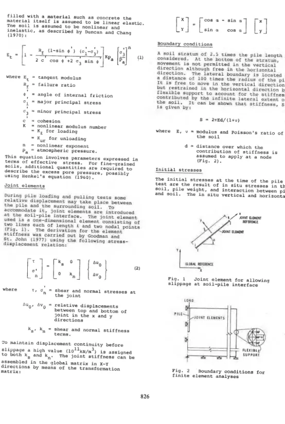
Reference Values of Quantities Used in Parametric Study
Fig. 5 Variation of slope of load-displacement curve with soil modulus.
Failure ratio R, 0.74
Angle of internal friction, @ 3 g 0
Cohesion, c' 26 kPa
Nonlinear modulus number
Ke for loading 700
Knr for unloading 2800
Nonlinear exponent, n 0.6
d
Young's modulus of steel 2 x 10' kPa Young's modulus of concrete 2.74 x lo7 kPa Poisson's ratio of soil 0.20
Coefficie'nt of earth pressure
at rest, 0.75
Friction factor, M 0.75 l o 1 0 0 1 0 0 0 l o 0 0 0
Initial skin friction 0.0 M O D U L U S N U M B E R . KJ 4 0 0 TOTAL LOADING FORCE y--~o--- 3 0 0 PULLIM; SHkFl
P
Z d 2 0 0 l o o- p
0 I I I 1 2 3 4 5 6 0 2 4 6 8 1 0 PlLE HEAD OlSRACEMENl I lo.! m RELATIVE LENGTH OF PlLE W W E SLIPPAGE OCCURREDFig. 4 Load-displacement curves and slippage along pile-shaft during pile tests.
Ftg. 6 Variation of M
with a soil modulus. ur/M1
Figure 5 shows the slope of tne linear portion of the load-displacement curve. This is defined as the force required to cause unit displacement at the pile head and generally increases with soil modulus. At the same modulus number the slope for loading, Me, is larger than the slope for pulling, MU,, because of the difference in tip resistance and normal stresses on the pile shaft. For most soils, however, K,,_ is larger than
--
K, and the resulting MSsr
--
may be higher than Me for the same material, as shown in Fig. 6 for three values of K ~ ~ / K ~ .1 7 1 1 I ? P I L E HIAO "J 0.8
-
0.9-
P l l t l l P l . O L'
'
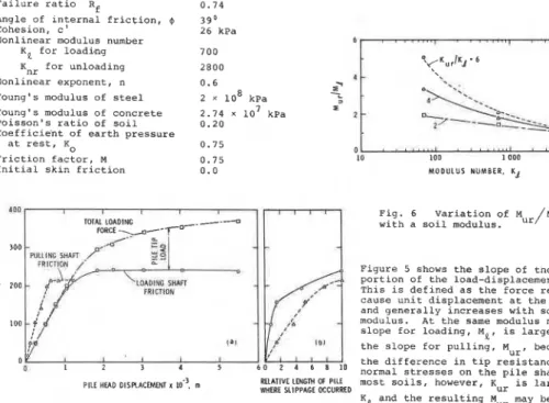
I I 0 10 20 10 40 IO 60 I R 80 S T R E S S , k P aFig. 7 Effective lateral stresses at soil-pile interface at failure in
loading tests.
P I L E H E A D
" ,
SYMBOL\-.
IS T R E S S . k P a
Fig. 8 Effective lateral stresses at soil-pile interface at failure in
pulling tests.
The ratio --, M, exceeds 1.0 for more .- compressible soil (low modulus number) and approaches 1.0 for stiff soil. Mur, Me exceeding 1.0 has been observed (~ansur and Hunter 1970; Bozozuk et al. 1979).
The effective lateral stresses on the pile shaft at failure are shown in Figs. 7 and 8. For loading tests (Fig. 7) there is a general increase in effective lateral stresses, except near the tip where the soil tends to spread outwards as a result of tip load. The less the compressibility of the soil, the higher is this lateral stress increase. Thus, shaft frictiqn at failure will increase with stiffer soil, as .shown in Fig. 9. On the other hand, effective
lateral stresses decrease for the pulling tests (Fig. 8 ) . dropping to zero near the pile head for very stiff soil. The shaft friction at failure is accordingly lower than that in the loading tests (Fig. 9). The ratio between shaft friction for loading failure and that for pulling failure ranges from 1.06 to 2;17, the higher number being associated with the stiffer soil and with higher KUr, xe ratio.
Effects of initial skin friction
The existence of initial skin friction, as described by Eq. (6a) and (6b). affects the stress distribution resulting from load application. Tnis in turn influences the slope of the load-displacement curve, the transference of the load to the pile tip, and the failure shaft resistance. These aspects may be studied by comparing results from analyses with and without initial skin friction.
Figure 10 shows how the slopes of the linear portion of the load-displacement curves ME and MUr are affected by initial skin friction. There is a reduction of about 30 to 40% in slope MUr for the pulling tests; and a reduction in Me for the loading case when the modulus number is less than 2000. Beyond this value the initial skin friction appears to increase the value of Me.
0 . 8 ' ' . ' . ' . ' I '
.
. * ' ' ' . ' '' ' "J
10 100 1 000 10 on0
M O D N U S NUMBER UJ
Fig. 9 Ratio of failure shaft friction in loading to that in pulling versus modulus number.
WITH INITIAL
'.
'.
C 20 WlMOUT INITIAL ' 0--
LO LOO 1000 10 000MOWLUS NUMBER. KJ OR Kyr MODULUS NUMBER. KJ OR K u r
Fig. 10 Influence of initial skin friction Fig. 11 Effect of initial skin friction on
on slopes of load-displacement curves. pile tip load at total load of 200 kN.
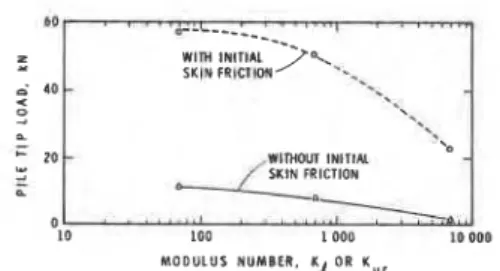
The load transferred to the pile tip at a given total load of 200 kN is shown in Fig. 11. In the absence of initial skin friction, hardly any load is felt at the tip. With the
introduction of initial skin friction, however, a significant tip load is found, particularly when soil compressibility is high. This is in agreement with observations of actual pile loading tests in London Clay reported by Cooke
(1979). For bored cast-in-place piles involving little initial skin friction, Cooke showed that the proportion of total load reaching the pile tip is extremely small. For jacked piles experiencing large negative initial skrn friction, the mobilization of tip load is high during the subsequent pile test. The failure shaft resistance developed with and without initial skin friction is shown in Fig. 12. In general, the effect of initial skin friction is small except for pulling tests in stiff soil where a significant reduction of shaft resistance may be obkerved.
Effects of loading history on pulling tests
A significant number of pulling tests were
conducted following completion of the loading tests. Some residual stresses were created, therefore, at the beginning of the pulling test and their effects were studied using analyses in which the pile was loaded to failure, then unloaded to zero, and pulled out to reach failure again.
Tho srres6 distribution around the plla a t the
end
of
unloading is ahown I n Fig. 13. Shaftfrrctlorb 16 generally neqatlve along the upper
portlon of the p l l e and posltlve along the
lower poruon. For the mare r i q ~ d 6011, near
zero frlctron Is found near the pile head. For
all cases the net shafk trzctlon 16 negative
and 1 s bnlanced by s residual load at rne tip.
The presence of a resrdual tlp load subsequent
t 3 unloddl ng. from an actual loadlng test, has been reported (Whltaker and C a k e 1966: and Hanna and Tan 1973).
The influence of residual stresses on shaft friction at pulling failure is shown in Fig. 14. It is small for very compressible
soil (KUr = 280). but there is a drastic
reduction in shaft friction when the soil is
less compressible. For Kur = 28,000 the ratio
Z
LMDIIX;
e z -
hLOO 1000 lo 000 LOO 000
MODULUS NUMBER. KJ OR Kur
Yrg. 12 Influence of initial skin friction
on failure shaft friction.
-30 -20 -10 0 10 20 30 SHAFT F R I C T I O N . k P a
Fig. 13 Distribution of shaft friction at
end of unloading after pile loaded to failure in compressron.
MODULUS NUMBER. K,,,
Fig. 14 Effect of residual stresses from
loading and unloading on failure shaft friction in pulling.
of shaft friction at loading failure to shaft friction at pulling failure is equal to 2.5. Effects of properties of.pile material The mechanical properties of the pile material were varied to examine their effect on pile performance. In one series the Young's~modulus of the pile material was reduced to
1.4 x 10' kPa while the Poisson's ratio was
kept at 0.37. In the second series Poisson's ratio was the variable and the Young's modulus
was kept constant at 1.4 x 10⁷ kPa.
Table I1 summarizes the results of the first analysis series. By using a softer material for the pile, the slope of the load-displacement curve is reduced, for the present cases, by about 30 to 40% in loading and by about 50% in pulling. There is a small decrease of about 10% in failure shaft friction in pulling and hardly any change in loading.
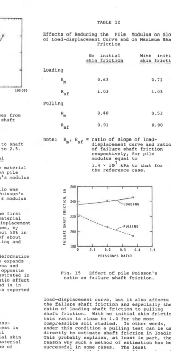
Poisson's ratio affects the lateral deformation of the pile. During loading the pile expands laterally, increasing the normal stress and hence the friction on the shaft: the opposite is true during pulling. This is illustrated in Fig. 15, which shows the Poisson's ratio effect on failure shaft friction. This trend is in qualitative agreement with the results reported by Bozozuk et al. (1979).
PRACTICAL IMPLICATIONS
Numerical analyses show that the stress- deformation condition during a pile test is affected by a number of factors: soil compressibility, development of initial skin friction, loading history, and pile material properties. Each has a varying degree of influence on pile performance.
For a given set of shear strength parameters,
c' and $ ' , soil compressibility appears to be
the most important factor. Not only does it alter significantly the slope of the
TABLE I1
Effects of Reducing the Pile Modulus on Slope of Load-displacement Curve and on Maximum Shaft
Friction
No initial With initial
skin friction skin friction
Loading ' m 0.63 0.71 Rsf 1.03 1.03 Pulling ' m 0.48 0.53
Note: Rm, Rsf = ratio of slope of load-
displacement curve and ratio of failure shaft friction respectively, for pile modulus equal to
1.4 x lo7 kPa to that for
the reference case.
P O I S S O N ' S R A T I O
Fig. 15 Effect of pile Poisson's
ratio on failure shaft friction.
load-displacement curve, but it also affects the failure shaft friction and especially the ratio of loading shaft friction to pulling shaft friction. With no initial skin friction, this ratio is close to 1.0 for the most compressible soil studied. In other words, under this condition a pulling test can be used directly to estimate shaft friction in loading. This ~robablv exulains. at least in Dart. the
-
~.
~~-reason why sich
H
methbd of estimation has beensuccessful in some cases. The least compressible soil, however, yields a value of
1.86. This means that to apply the pulling
test result directly will grossly under- estimate shaft friction in loading. It will be worse if there is initial skin friction or a large difference between loading and unloading
moduli, or if the pulling test follows the loading test. The loading and pulling tests snould therefore be interpreted in the light of such factors as those studied herein.
Otherwise, this relatively simple and
economical approach may not produce the desired result.
The numerical analyses yield a ratio of loading-to-pulling shaft friction of a range similar to that observed in field pile tests. The analyses fail to indicate the very high values measured in the laboratory by Mazurkiewicz (1968). One possible reason is that tne numerical method better simulates the boundary conditions than does the laboratory apparatus. If this is the case. more care mav
soil-pile interface, initial stresses existing in the ground and on the pile shaft, and boundary conditions similar to tnose in the field. When a parametric study was carried out on a sandy soil, the results showed that pile performance depends on a number of factors, with soil compressibility the most important. For a pile installed in very compressible soils, the assumption that shaft friction In pulling is the same as that in loading is approximately correct. For stiffer soils, the shaft friction in loading, however. exceeds that in pulling, in some cases by up to 150%. Such agreement and disagreement of the assumption have both been observed in the literature.
be- required in comparing pile test results.
laboratory and field-
ACKNOWLEDGEMENT
S U W R Y AND CONCLUSIONS
A finite element method used to study the performance of a pile during loading and pulling tests takes into account nonlinear and inelastic soil behaviour, slippage at the
The author gratefully acknowledges valuable discussions with his colleague. M. Bozozuk, during the preparation of this paper. It is a contribution from the Division of Buildinq Research, National Researcn Council of caiada, and is published with the approval of the Director of the Division.
REFERENCES
Baguelin, F., and Jezequel, J.F. (1971). itude exp6rimentale de fondations profondes rigides sollicitees horizontalement. Laboratoire Central des Ponts et Chaus6es. wpartement aes Sols, Paris, Report No. 71-8687.
Bengtsson, P.E.. and Sallfors, G. (1979). Floating piles in soft, hlghly plastic clavs. Pre~rint Volume of 32nd Canadian ~eotechnicai Conference, Quebec City, P.Q. 4.50-4.70.
Bozozuk, M. (1972). Downdrag measurements on a 160 ft floating pipe test pile in marine clay. Canadian Geotechnical Journal, (9) 127-136.
Bozozuk. M., Keenan, G.H., and Pheeney, P.E. (1979). Analysis of load tests on instrumented steel test piles in compressible silty soil. Behaviour of Deep Foundations. (Raymond Lundgren, Ed.), American Society for Testing and
Materials, STP 670, 153-180.
Broms, B.B., and Silberman, J.O. (1964). Skin friction resistance for piles in
cohesionless soils. Sols Soils, Revue Internationale, Mechanique des sols et travaux de fondations, (111) 10, 33-41. Chanaler, R.J. -(1563). The shaft friction of
piles in conesive soils in terms of effective stress. Civil Engineering and Public Works Review, (63) 48-51.
Chang. C.Y., and Duncan, J.M. (1970). Analysis Of soil movements around d e e ~ excavation. Journal of Soil Mechanics an; Foundation Division, ASCE (96) SM5, 1655-1681.
Cooke, W. (1979). Influence of residual installation forces on the stress transfer and settlement under working loads of jacked and bored piles in cohesive soils. Behaviour of Deep Foundations. (Raymond Lundgren, Ed.), American Society for Testing and Materials, STP 670, 231-249. Duncan, J.M. and Chang, C.Y. (1970). Nonlinear
analysis of stress and strain in soils. Journal of the Soil Mechanics and Foundation Division, ASCE (46) SM5, 1629-1654.
Fellenius, B.H. (1972). Down-drag on piles in clay due to negative skin friction. Canadian Geotechnical Journal (9) 323-337. Fellenius, B.H., and Samson, L. (1976). Testing
of drivability of concrete piles and disturbance to sensitive clay. Canadian Geotechnical Journal (13) 2, 139-160. Goodman, R.E., and St. John, C. (1977). Finite
element analysis for discontinuous rocks. In Numerical Method in Geotechnical
-
Engineering. McGraw-Hi11 Book Company, 148-175.
Hanna, T.h., and Tan, R.h.S. (1971). The load movement behaviour of long piles. Journal of Materials, JMLSA, (6) 3, 532-554. Hanna, T.H., and Tan, R.H.S. (1973). The
behaviour of long piles under compressive loads in sand. Canadian Geotechnical Journal (10) 311-340.
Henkel, D.J. (1960). The shear strength of saturated remoulded clavs. Proc.. ASCE Research Conference On Shear Strength of Cohesive Soils, Boulder, Colorado, 533-554.
Mansur, C.I., and Hunter, A.H. (1970). Pile tests
-
Arkansas River Project. Journal of the Soil Mechanics and Foundation Division, AsCE, (961 SM5, 1545-1582. Mazurkiewicz, B.K. (19681. Skin friction onmodel piles in sand. The Danish Geotechnical Institute, Copenhagen, Bulletin No. 25.
Sowa, V.A. (1970). Pulling capacity of concrete cast in situ bored piles. Canadian Geotechnical Journal (7) 482-493. V6sic. A.S. (1970). Tests on instrumented
piles, Ogeechee River site. Journal of soil Mechanics and Foundation Division, ASCE, (96) SM2, 561-584.
Whitaker, T., and Cooke, R.W. (1966).
An investigation of the shaft and base resistance of large bored piles in Leda clay. Symposium on Large Bored Piles. Institution of Civil Engineers, London, 7-49.
Zienkiewicz, O.C. (1971). The finite element method in engineering science. London, McGraw-Hill.
Zienkiewicz, O.C., Valliappan, S. and King, I.P. (1968). Stress analysis in rock as a 'no-tension' material. Geotechnique (18) 55-66.