HAL Id: hal-01220807
https://hal.archives-ouvertes.fr/hal-01220807
Submitted on 27 Oct 2015
HAL is a multi-disciplinary open access
archive for the deposit and dissemination of
sci-entific research documents, whether they are
pub-lished or not. The documents may come from
teaching and research institutions in France or
abroad, or from public or private research centers.
L’archive ouverte pluridisciplinaire HAL, est
destinée au dépôt et à la diffusion de documents
scientifiques de niveau recherche, publiés ou non,
émanant des établissements d’enseignement et de
recherche français ou étrangers, des laboratoires
publics ou privés.
Magnets
Cécile Daversin, Christophe Prudhomme, Christophe Trophime
To cite this version:
Cécile Daversin, Christophe Prudhomme, Christophe Trophime. Full 3D MultiPhysics Model of High
Field PolyHelices Magnets. IEEE Transactions on Applied Superconductivity, Institute of Electrical
and Electronics Engineers, 2016, 26 (4), pp.1-4. �10.1109/TASC.2016.2516241�. �hal-01220807�
Full 3D MultiPhysics Model of High Field
PolyHelices Magnets
C´ecile Daversin, Christophe Prudhomme and Christophe Trophime
Abstract—High field Resistive magnets for static field de-veloped at the Laboratoire National des Champs Magn´etiques Intenses (LNCMI) are based on the so-called polyhelix technique. Their design relies on non-linear 3D multi-physic models. As the user demands for higher magnetic field or specific field profile are growing we have to revisit our numerical models. They need to include more physics and more precise geometry. In this context we have rewritten our numerical model in the frame of a collaboration with Institut de Recherche en Math´ematique Avanc´ee (IRMA). New models have been implemented with the finite element library Feel++. This paper gives a status of these developments and the new features available. Results are presented for a 14 polyhelices insert targeting 36 Tesla in a 34 mm bore.
Index Terms—Magnets, Magnetic fields, Multi-physics Analy-sis.
I. INTRODUCTION
The LNCMI is a French large scale facility [1] enabling researchers to perform experiments in the highest possible magnetic field. DC magnetic fields up to 36 T are provided at the Grenoble site and pulsed fields up to 90 T at Toulouse. The technology used for DC magnets relies on the so-called polyhelix inserts for the most stressed parts of the magnets [2]. To design efficiently such magnet multi-physic models are mandatory.
A common practice in magnets design consists in using several commercial software, each of them dedicated to a specific physic, to deal with the coupled phenomena involved. On top of these codes, several homemade software have to be developed to ensure the actual coupling either for the meshes used either for the input data to be exchanged between models. Such a magnet design process may be found in [3].
To avoid the burden of writing and maintaining dedicated interfaces or scripts to glue several software together, more integrated approach may be considered using general purpose finite element codes (eg. Ansys, Comsol). But still this ap-proach may also exhibits some limits especially when meshing the magnet geometry provided by some CAD software.
At the light of these observations, we have decided to rework our design process [4] by using a single software based on modules dedicated each to a specific physic. The data needed to ensure the couplings are integrated within the
C. Daversin and C. Prudhomme are with the Institut de Recherche Math´ematique Avanc´ee (CNRS, Univ. Strasbourg), France
C. Trophime is with the Laboratoire National des Champs Magn´etiques Intenses (CNRS, Univ. de Grenoble, UPS, Insa), Grenoble, France (phone: +33 4 76 88 90 02; e-mail: [email protected], Web site http://lncmi.cnrs.fr)
Manuscript received October 20, 2015.
software. The developments have been carried in the frame of a collaboration with IRMA from University of Strasbourg using their Finite Element library Feel++ (www.feelpp.org) [5]. As for the meshes they are obtained from a geometry built with OpenSalome CAD/CAE platform [6] which greatly eases this step thanks to its Python interface. This approach is quite similar to the one developed in [7].
In this paper we present in more details our approach. We illustrate the progress achieved with the study of a polyhelix resistive insert planed to be operated in the future hybrid magnet [8]. Finally, we demonstrate the possibility offered by Reduced Order Methods in this context to perform uncertainty quantification in our design. This work enjoys the Reduced Basis framework available in Feel++ library.
II. APPROACH
As mentioned in [7] the design and optimization of magnets is an iterative process that involves numerical multiphysics modeling, namely eletromagnetics, thermics and mechanics. In the case of resistive magnets we also have to consider thermo-hydraulics as our magnets are water cooled. This aspect is treated with standard Colburn correlation that won’t be detailed in the sequel. The heat exchange between water and resistive magnet is governed by forced convection. This is modeled by adding a boundary condition on the water flux, depending on heat transfer coefficient and water temperature. This process always starts with some initial guessed magnet geometries provided by some optimization procedure. In our case the initial polyhelix magnet geometry, made of concentric copper alloy tubes, is derived from an optimization of the cur-rent density distribution in each tube based on an axisymetrical semi-analytical model [9]. This procedure actually provides the helical path for each tube which will be cut by electro discharge machine. The cut is then either filled with a mix of glass spheres and epoxy glue to produce ”longitudinally cooled helix”, either let free with the exceptions of insulators disposed at regular angles to produce ”radially cooled helix” (for details see [2]).
Once the helical path is determined, an automatic procedure may be derived to create the actual helix CAD geometry. Thanks to its Python interface, this operation may be carried out without human interaction within Salome. However spe-cial care has to be taken to properly define interfaces between copper and insulators in case of radially cooled helices. This is mandatory to have conformal meshes with may also be built via the Python interface. In our experience we only manage to have this CAD and Meshing steps using Salome. On fig. 1 is
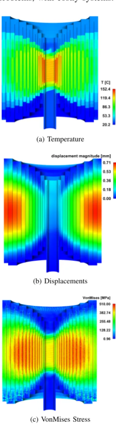
Fig. 1. A 14 Helices resistive insert with current leads
given a CAD view of a 14 helices resistive insert with current leads. The whole insert geometry is automatically generated with Python scripts. This allows to easily take into account some geometric parameters if ever needed during the design process. At this point we can perform simulations using our numerical models.
Our model is splitted into 3 modules which can be coupled at will in the main software. The configuration of this coupling can be easily managed by users from a configuration file, without any act on the code itself. The Electro-Thermal model computes the electrical potential V and the temperature field T by solving a set of two non-linear PDEs as the physical properties of the copper alloys are temperature dependent. The Elasticity module computes the displacements and stresses (Tresca, Von-Mises) from both thermal dilatation and Lorentz forces by solving the linear elasticity equation. Finally the Magnetostatic module computes the magnetic vector potential and the induction field B, often abusively referred as the magnetic field H. The computation of B field in the region of interest for the researchers from the current distribution j = −σ(T )∇V is also provided, based on the Biot and Savart’s law.
These modules have been developed with Feel++. This stands for Finite Element Embedded Language in C++ (see www.feelpp.org). The formalism behind Finite Element Method, variational formulations, is embedded into C++. This way we can reduce the semantic gap between mathematics and the code. The library enables user to perform simulations with both high order finite elements and high order meshes. It is in-terfaced with large scale parallel linear and non-linear solvers, and enjoys seamless parallel computing possibilities enabling use from workstation to supercomputers without changes. Owning to these features, our modules may benefits to state of the art techniques and most important can be easily port and use on parallel computers. This is an important point in the perspective of magnet design. Indeed the higher magnetic field we are trying to reach, the more detailed analysis we need. This implies to consider more physics and more precise geometrical modeling in our simulation. Consequently it leads
to large scale problems, with costly systems.
(a) Temperature
(b) Displacements
(c) VonMises Stress Fig. 2. Displacements and stress
III. AN EXAMPLE: 14 HELIXINSERT
To illustrate the status of our developments, we take the example of the Hybrid 14 insert made of CuAg alloy in a background field of 17.7 Tesla provided both by a set of Bitter coils and by superconducting outer insert. The main characteristics of the insert is given in tab. I.
The simulations were carried out on the geometry depicted on fig. 1. At the time of the writing the full 3D Magnetostatic module was not fully validated and hence has not been used to compute B in the helices. For this step, we have reverted to the semi-analytical axisymetrical expression of B obtaining during the optimization step. The mesh used has about 6.4·106 tetras and 106nodes. The total CPU time on 32 processors is about ≈ 20 min. Detailed CPU time for each module is given in tab. II.
TABLE I MAINCHARACTERISTICS
Current 30 kA
Power 12.5 MW
Water flow 25 m/s Pressure drop 20 bars Inner diam. 38.6 mm Outer diam. 372 mm
H 315 mm
Water Temp. (Tw) from 20 to 40C h 85000 W/m2/K B 27 T (+ 17.7 background field)
TABLE II
REPARTITION OFCPUTIME BETWEEN MODULES
Electro-thermal (8 Picard iterations) 631 s Magnetostatic (2D axi) 575 s Elasticity 103 s
The results are displayed on fig. 2a to 2c. As expected the maximum temperature is reached in the innermost helices. The maximum Von-Mises stress is obtained in the intermediate helices and reaches 510 Mpa. The displacements are about 0.7 mm for the outermost helices. This values correspond to a field of 44.5 Tesla which fulfill our requirements for the Hybrid magnet to be operational in 2018.
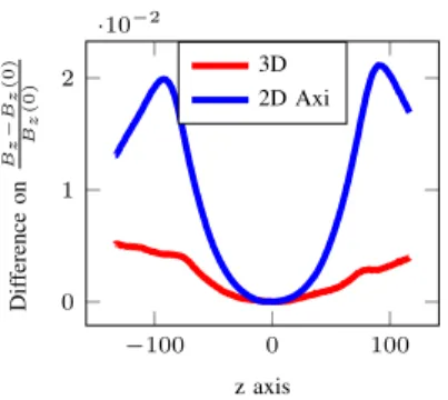
To validate our models we have also run simulations on existing polyhelices insert. As the experimental data are very limited we have restricted ourselves to the comparison of B along the central axis of the insert. Measures were performed with a pick-up coil, calculations were carried out using the semi-analytical expression from the optimization procedure and with our 3D Biot-Savart parallel implementation in the Magnetostatic module. The results show a great agreement between the measures and the calculations. A detailed analysis shows that with our 3D Biot-Savart we have a more precise view on B. The error at the vicinity of the entrance and exit of the magnet is improved by a factor 2 (see fig. 3).
−100 0 100 0 1 2 ·10−2 z axis Dif ference on Bz − Bz (0) Bz (0) 3D 2D Axi
Fig. 3. Comparison of the profile of B vs the experimental data along z axis obtained by 2D axi B (from optimization step) and 3D Biot-Savart calculations
IV. TOWARDS A ROBUST DESIGN
In the previous paragraph the status of our models was illustrated on a concrete example. However during a classical
design process we would like to run such kind of simulations to explore some parametric space, for instance to evaluate the impacts of some parameters either geometric or physical. Moreover we would like to be able to evaluate the impact of some uncertainties, for instance on material physical properties on some quantities of interest, such as the magnetic field at some given points, the mean temperature of the magnet, or the total power.
A lot of simulations would then be required to explore this parametric space and to address these questions. Even if we have some quite efficient tools the computational cost associ-ated may become rapidly unaffordable. Fortunately Feel++ provides a Reduced Basis Method framework [10] that can tackle this kind of situations.
From a naive point of view, Reduced Basis Method [11] may be seen as a kind of interpolation for the Finite Ele-ment method. The idea consists in making a smart selection of some points in the parameter space and performing the associated finite element approximations. The Reduced Basis approximation for any set of parameters then reads as a linear combination of these previously computed and stored solutions - the so-called reduced basis.
Whereas the first step -selecting and computing some finite element solutions - often referred as the offline step is time consuming, the second one - the interpolation of the reduced solution - referred as the online step is very light in comparison since the associated system to solve has a greatly reduced size - from 10 to 100 basically, compared with few million.
Fig. 4. Temperature in K within a radially cooled helix with a zoom of on insulators in the central zone.
As an application of the reduced basis method, we will consider a radially cooled helix. This kind of helices - better cooled than the longitudinal ones - are foreseen to replace the innermost helices of the resistive polyhelices insert which are mostly thermally limited. In this context we investigate the mean temperature in such an helix in the actual range of parameters representative of nominal operating conditions with an current intensity around 31kA :
h ∈ [70000; 90000](W.m−2.K−1) Tw∈ [293, 313](K)
We have also considered some uncertainties on the copper physical properties : the electrical conductivity is of the form σ = σ0/(1 + α(T − T0) and the thermal conductivity is given
by the Wiedemann-Frantz law k = LσT : σ0∈ [50.106; 50, 2.106](S.m−1) α ∈ [3, 3.10−3; 3, 5.10−3](K−1) L ∈ [2, 5.10−8; 2, 9.10−8]
For this example we have used a set of 10 reduced basis. Once the basis are computed, the evaluation of a solution is about 150 faster than solving the finite element problem. Evaluations of the mean temperature has been performed on a set a 300 samples of the parameter spaces. This allows the use of openturns [12] to perform some statistics on the results. The interested reader can find more details about implementation in [10].
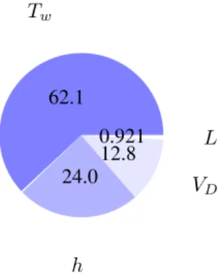
For this parameter space, the ”mean” temperature is 95◦C with an standard deviation of 6.2 ◦C. With this analysis we may also have access to quantiles, that is, value of the mean temperature that may not be exceed at a given probability. In the present case, we show that the mean temperature may not exceed 107◦C at 99%. These quantiles may be useful to set up tighter bounds on the threshold for the magnet control system. In addition we also have access to the Sobol indices (see fig 5 which represents the influence of the parameters on the output, here the mean temperature. From a practical engineering point of view the Sobol indices provide some guidelines on which parameters should acted upon to improve the target output. In this case, the most influential parameter turns out to be the water temperature. 62.1 Tw 24.0 h 12.8 VD 0.921 L
Fig. 5. Sensitivity indices (Sobol) for the mean temperature. Only the most significant ones have been plotted.
V. CONCLUSION ANDPERSPECTIVES
The design of magnets at the LNCMI, beside the initial optimization step, have been reworked from scratch in the frame of a collaboration with IRMA using their state of the art finite element library Feel++. Combined with the automation of CAD/Meshing procedure introduced using Salome plat-form Python interface we have set the first steps towards a software toolchain dedicated to resistive high field magnets. Following a similar approach to [7] we plan to integrate more tightly our numerical models with Salome. Thus doing we will have a complete and integrate software with user-friendly GUI facilities which may be used routinely in a R & D context. Our choice to base our design and optimization tools on Feel++ and Salome has been illustrated on the study
resistive polyhelices. Since these two software are opensource we can easily port and use our toolchain on parallel computers at moderate cost compared to commercial solutions. Finally Feel++permits to envision the development of more robust design by using its reduced basis method framework to per-form sensitivity analysis and uncertainties quantifications like in the last example.
In parallel to these developments we will improve our models by adding some more physics in it - especially to account for the non-linearity in the elasticity model and to have better insights of the cooling flow and heat exchange. We are also enriching our reduced Electro-thermal model, to go towards a multi-physics reduced model including magneto-statics and mechanics. From associated quantities of interest, this will provide further uncertainty quantification to be used in optimization process.
ACKNOWLEDGMENT
The authors acknowledge PRACE for awarding us access to Curie supercomputer based in France at TGCC. We also acknowledge the French Research Agency which support this work through the project CHORUS as well as the Labex IRMIA.
REFERENCES
[1] J. Bard and F. Debray, “The french high magnetic field facility,” Journal of Low Temperature Physics, vol. 170, no. 5-6, pp. 541–552, 2013. [Online]. Available: http://dx.doi.org/10.1007/s10909-012-0761-x [2] F. Debray, J. Dumas, C. Trophime, and N. Vidal, “Dc high field magnets at the lncmi,” Applied Superconductivity, IEEE Transactions on, vol. 22, no. 3, pp. 4 301 804–4 301 804, June 2012.
[3] J. Toth and M. Bird, “Fea-aided design for a working model of a split florida-helix,” Applied Superconductivity, IEEE Transactions on, vol. 18, no. 2, pp. 575–578, June 2008.
[4] C. Trophime et al., “Magnet calculations at the grenoble high magnetic field laboratory,” IEEE Trans. Appl. Superconduct., vol. 12, no. 1, pp. 1483–7, June 2002.
[5] C. Prud’homme, “A domain specific embedded language in C++ for automatic differentiation, projection, integration and variational formu-lations,” Scientific Programming, vol. 14, no. 2, pp. 81–110, 2006. [6] A. Ribes and C. Caremoli, “Salome platform component model for
nu-merical simulation,” in Computer Software and Applications Conference, 2007. COMPSAC 2007. 31st Annual International, vol. 2, July 2007, pp. 553–564.
[7] F. Nunio and P. Manil, “Salome as a platform for magneto-mechanical simulation,” Applied Superconductivity, IEEE Transactions on, vol. 22, no. 3, pp. 4 904 904–4 904 904, June 2012.
[8] P. Pugnat, R. Barbier, C. Berriaud, R. Berthier, F. Debray, P. Fazilleau, B. Hervieu, P. Manil, M. Massinger, C. Pes, R. Pfister, M. Pissard, L. Ronayette, and C. Trophime, “Progress report on the 43 t hybrid magnet of the lncmi-grenoble,” Applied Superconductivity, IEEE Trans-actions on, vol. 24, no. 3, pp. 1–5, June 2014.
[9] C. Trophime, S. Kramer, and G. Aubert, “Magnetic field homogeneity optimization of the giga-nmr resistive insert,” Applied Superconductivity, IEEE Transactions on, vol. 16, no. 2, pp. 1509–1512, June 2006. [10] C. Daversin, S. Veys, C. Trophime, and C. Prud’Homme, “A reduced
basis framework: Application to large scale nonlinear multi-physics problems,” Esaim Proc., vol. 43, pp. 225–254, Dec. 2013. [Online]. Available: http://hal.archives-ouvertes.fr/hal-00786557
[11] C. Prud’homme, D. V. Rovas, K. Veroy, L. Machiels, Y. Maday, A. T. Patera, and G. Turinici, “Reliable real-time solution of parametrized partial differential equations: Reduced-basis output bound methods,” Journal of Fluids Engineering, vol. 124, no. 1, pp. 70–80, 2002. [Online]. Available: http://link.aip.org/link/?JFG/124/70/1
[12] A. Dutfoy, I. Dutka-Malen, A. Pasanisi, R. Lebrun, F. Mangeant, J. S. Gupta, M. Pendola, and T. Yalamas, “OpenTURNS, an Open Source initiative to Treat Uncertainties, Risks’N Statistics in a structured industrial approach,” in 41`emes Journ´ees de Statistique, SFdS, Bordeaux (France), 2009.