3D Tracking via Body Radio Reflections
The MIT Faculty has made this article openly available.
Please share
how this access benefits you. Your story matters.
Citation
Fadel Adib, Zachary Kabelac, Dina Katabi, and Robert C. Miller.
2014. 3D tracking via body radio reflections. In Proceedings of
the 11th USENIX Conference on Networked Systems Design and
Implementation (NSDI'14). USENIX Association, Berkeley, CA, USA,
317-329.
As Published
http://dl.acm.org/citation.cfm?id=2616478
Publisher
Association for Computing Machinery (ACM)
Version
Author's final manuscript
Citable link
http://hdl.handle.net/1721.1/100522
Terms of Use
Creative Commons Attribution-Noncommercial-Share Alike
3D Tracking via Body Radio Reflections
Fadel Adib
Zachary Kabelac
Dina Katabi
Robert C. Miller
Massachusetts Institute of Technology
Abstract – This paper introduces WiTrack, a systemthat tracks the 3D motion of a user from the radio sig-nals reflected off her body. It works even if the person is occluded from the WiTrack device or in a different room. WiTrack does not require the user to carry any wire-less device, yet its accuracy exceeds current RF localiza-tion systems, which require the user to hold a transceiver. Empirical measurements with a WiTrack prototype show that, on average, it localizes the center of a human body to within a median of 10 to 13 cm in the x and y di-mensions, and 21 cm in the z dimension. It also provides coarse tracking of body parts, identifying the direction of
a pointing hand with a median of 11.2◦. WiTrack bridges a
gap between RF-based localization systems which locate a user through walls and occlusions, and human-computer interaction systems like Kinect, which can track a user without instrumenting her body, but require the user to stay within the direct line of sight of the device.
1
I
NTRODUCTIONRecent years have witnessed a surge in motion tracking and localization systems. Multiple advances have been made both in terms of accuracy and robustness. In par-ticular, RF localization using WiFi and other communica-tion devices has reached sub-meter accuracy and demon-strated its ability to deal with occlusions and non-line of sight scenarios [31, 18]. Yet these systems require the user to carry a wireless device in order to be localized. In contrast, systems like Kinect and depth imaging have revolutionized the field of human-computer interaction by enabling 3D motion tracking without instrumenting the body of the user. However, Kinect and imaging systems require a user to stay within the device’s line-of-sight and cannot track her across rooms. We envision that if an RF system can perform 3D motion tracking without requiring the user to wear a radio, it will motivate the integration of such a technology in systems like Kinect to expand their reach beyond direct line of sight and enable through-wall human-computer interaction.
Motivated by this vision, this paper introduces WiTrack, a system that tracks the 3D motion of a user using radio reflections that bounce off her body. It works through walls and occlusions, but does not require the user to carry any wireless device. WiTrack can also provide coarse tracking of a body part. In particular, the user may lift her hand and point at objects in the environment; the device detects the direction of the hand motion, enabling the user to identify objects of interest.
WiTrack has one antenna for transmission and three an-tennas for receiving. At a high level, WiTrack’s motion tracking works as follows. The device transmits a radio signal and uses its reflections to estimate the time it takes the signal to travel from the transmitting antenna to the re-flecting object and back to each of the receiving antennas. WiTrack then uses its knowledge of the position of the an-tennas to create a geometric reference model, which maps the round trip delays observed by the receive antennas to a 3D position of the reflecting body.
Transforming this high-level idea into a practical sys-tem, however, requires addressing multiple challenges. First, measuring the time of flight is difficult since RF signals travel very fast – at the speed of light. To distin-guish between two locations that are closer than one foot apart, one needs to measure differences in reflection time on the order of hundreds of picoseconds, which is quite challenging. To address this problem, we leverage a tech-nique called FMCW (frequency modulated carrier wave) which maps differences in time to shifts in the carrier fre-quency; such frequency shifts are easy to measure in radio systems by looking at the spectrum of the received signal. A second challenge stems from multipath effects, which create errors in mapping the delay of a reflection to the distance from the target. WiTrack has to deal with two types of multipath effects. Some multipath effects are due to the transmitted signal being reflected off walls and furniture. Others are caused by the signal first reflecting off the human body then reflecting off other objects. This is further complicated by the fact that in non-line-of-sight settings, the strongest signal is not the one directly bounc-ing off the human body. Rather it is the signal that avoids the occluding object by bouncing off some side walls. WiTrack eliminates reflections from walls and furniture by noting that their distance (and time of flight) does not change over time. Hence, they can be eliminated by sub-tracting consecutive frames of the signals. Reflections that involve a combination of a human and some static object are more complex and are addressed through filters that account for practical constraints on the continuity of hu-man motion and its speed in indoor settings.
We have built a prototype of WiTrack and evaluated it empirically. Since off-the-shelf radios do not perform FMCW, we built an analog FMCW radio frontend, which operates as a daughterboard for the USRP software radio. In our evaluation, we use the VICON motion capture sys-tem [6] to report the ground truth location. VICON can achieve sub-centimeter accuracy but requires
instrument-ing the human body with infrared markers and positioninstrument-ing an array of infrared cameras on the ceiling. Since VICON cannot operate in non-line-of-sight, the human moves in the VICON room while our device is placed outside the room and tracks the motion across the wall. Our evalu-ation considers three applicevalu-ations, each of them uses the developed 3D tracking primitive in a different way.
In the first application, we consider 3D tracking of hu-man motion through a wall. The objective of such an ap-plication is to augment virtual reality and gaming systems to work in non-line-of-sight and across rooms. We com-pute the tracking error as the difference between the loca-tion reported by our device and the actual localoca-tion of the body center as reported by VICON. Our results show that WiTrack localizes the center of the human body to within 10 to 13 cm in the x and y dimensions, and 21 cm in the z dimension. This high accuracy stems from WiTrack’s ability to eliminate errors due to multipath and the com-bined performance of FMCW and our geometric mapping
algorithm. The results also show that even the 90th
per-centile of the measurements stays within one foot along the x/y-axis and two feet along the z-axis.
In the second application, we consider elderly fall de-tection. Current solutions to this problem include inertial sensors which old people tend to forget to wear [15], or cameras which infringe on privacy, particularly in bed-rooms and bathbed-rooms [20]. In contrast, WiTrack does not require the user to wear any device and protects her pri-vacy much better than a camera. However, simply looking at the change in elevation cannot allow us to distinguish a fall from sitting on the floor. Thus, WiTrack identifies a fall as a fast change in the elevation that reaches the ground level. In a population of 11 users and over 133 experiments, WiTrack distinguishes a fall from standing, walking, sitting on a chair and sitting on the floor with an accuracy of 96.9% (the F-measure is 94.34%).
In the third application, we consider a user who desires to control appliances by pointing at them (e.g., the user can turn her monitor on or turn the lights off by simply pointing at these objects.) We consider a gesture in which the user lifts her arm, points at an appliance, and drops her arm. By comparing the position of the arm over time, WiTrack can identify the pointing direction. Our proto-type estimates the pointing direction with a median of
11.2 degrees and a 90thpercentile of 37.9 degrees.
Our results also show that the prototype operates in re-altime, and outputs the 3D location within 75 ms from the time the antennas receive the signal. Further, it operates at a fairly low-power, transmitting only 0.75 milliwatts. However, our current prototype can track a single person, and requires the person to move to obtain an initial esti-mate of his location.
Contributions: This paper introduces the first device that can achieve centimeter-scale accuracy in tracking the 3D
(a) Antenna “T” Setup (b) FMCW Signal Generation
Figure 1—WiTrack’s Setup and Signal Generation. (a) shows WiTrack’s directional antennas (dimension of each antenna: 5cm × 5cm) arranged in a “T”: the transmit antenna is placed at the crossing point of the T, whereas the receive antennas are on the edges. (b) shows the hardware we built to generate FMCW signals.
motion of a human based on radio reflections off her body. The paper presents new algorithms for eliminating errors due to multipath and performing accurate 3D tracking, both of a whole body and a body part. The paper also presents a prototype implementation that includes a low-power FMCW radio frontend and realtime processing, de-livering accurate 3D motion tracking to within a median of 10 to 20 centimeters.
Our results demonstrate that WiTrack can expand the space of human-computer interfaces and enable interac-tion across walls, and occluded spaces. We believe that WiTrack also expands the role that wireless computer net-works may play in the future to enable them to provide a variety of services: Communication is definitely a major service, but other services may include motion tracking, through-wall human-computer interaction, and a gesture based interface for controlling appliances and interacting with the environment.
2
W
IT
RACKO
VERVIEWWiTrack is a wireless system that performs 3D motion tracking in both line-of-sight and through wall scenarios. It can also provide coarse tracking of body parts, like an arm movement. WiTrack uses multiple directional anten-nas: one antenna is used for transmitting, and three an-tennas for receiving. In its default setup, the anan-tennas are arranged in a “T” shape, as shown in Fig. 1(a). In its cur-rent version WiTrack tracks one moving body at any time. Other people may be around but should be either behind
the antenna beam or they should be approximately static.1
WiTrack operates by transmitting an RF signal and cap-turing its reflections off a human body. It tracks the mo-tion by processing the signals from its received antennas using the following three steps:
1. Time-of-Flight (TOF) Estimation: WiTrack first mea-sures the time it takes for its signal to travel from its transmit antenna to the reflecting body, and then back to each of its receive antennas. We call this time the
1Small moving objects which do not have significant reflections (e.g.,
a plastic fan) create some noise but do not prevent WiTrack’s 3D track-ing.
TOF (time-of-flight). WiTrack obtains an initial mea-surement of the TOF using FMCW transmission tech-nique; it then cleans this estimate to eliminate multi-path effects and abrupt jumps due to noise.
2. 3D Localization: Once it obtains the TOF as perceived from each of its receiving antennas, WiTrack leverages the geometric placement of its antennas to localize the moving body in 3D.
3. Fall Detection and Pointing: WiTrack builds on the 3D localization primitive to enable new functionali-ties. Specifically, WiTrack can detect a fall by moni-toring fast changes in the elevation of a human and the final elevation after the change. WiTrack can also dif-ferentiate an arm motion from a whole body motion; it can track the motion of raising one’s arm, localize the initial and final position of the arm, and determine the direction in which the arm is pointing.
3
T
IME-
OF-F
LIGHTE
STIMATIONThe first step for WiTrack is to measure the TOF from its transmit antenna to each of its receive antennas and clean this estimate from the effect of multi-path.
3.1 Obtaining Time-of-Flight Estimates
A straightforward approach for estimating the time of flight is to transmit a very short pulse and measure the delay between the transmitted pulse and its received echo. Such a design requires sampling the signal at sub-nanosecond intervals – i.e, it requires high speed analog-to-digital converters (ADCs) that operate at multi-GS/s. Such ADCs are high power, expensive, and have low bit resolution, making this approach unattractive in practice.
Instead, WiTrack measures the TOF by leveraging a technique called Frequency-Modulated Carrier Waves (FMCW). We explain FMCW at a high level, and re-fer the reader to [19] for a more detailed explanation. FMCW transmits a narrowband signal (e.g., a few KHz) whose carrier frequency changes linearly with time. To identify the distance from a reflector, FMWC compares the carrier frequency of the reflected signal to that of the transmitted signal. Since the carrier frequency is chang-ing linearly in time, delays in the reflected signals trans-late into frequency shifts in comparison to the transmitted wave. Therefore, by comparing the frequency difference between the transmitted signal and the received signal, one can discover the time delay that the signal incurred, which corresponds to the TOF of that signal.
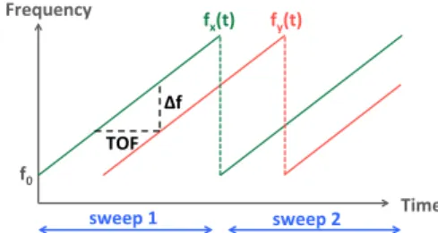
Fig. 2 illustrates this concept. The green line is the car-rier frequency of the transmitted signal which sweeps lin-early with time. The red line is the carrier frequency of the reflected signal as a function of time. The time shift between the two is the time-of-flight (TOF) for that re-flector. The frequency shift ∆f between the transmitted and received signals is a function of both the slope of the sweep and the TOF, i.e.:
TOF= ∆f /slope (1) f0# Time# fx(t)# fy(t)# Δf# TOF# sweep#1# sweep#2# Frequency#
Figure 2—FMCW operation. The transmitted signal has a carrier
fre-quency fx(t) that is repeatedly swept in time. Because the received
sig-nal is time-shifted with respect to the transmitted sigsig-nal, its carrier
fre-quency fy(t) is frequency-shifted with respect to fx(t).
Though the above description is for a single reflector, it can be easily generalized to an environment with many reflectors. In this case, the transmitted signal would still consist of a single carrier wave that is linearly swept in time. However, because wireless reflections add up lin-early over the medium, the received signal is a linear com-bination of multiple reflections, each of them shifted by some ∆f that corresponds to its own TOF. Hence one can extract all of these TOFs by taking a fourier transform (i.e,
an FFT) of the received baseband signal.2
In comparison to transmitting a very short pulse and measuring its sub-nanosecond delay in the time domain, FMCW does not require high speed ADCs because at any point in time, the received baseband signal is narrowband. FMCW Resolution: It is important to note that the reso-lution of an FMCW system is a function of the total band-width that the carrier frequency sweeps [19]. The resolu-tion is defined by the ability to distinguish between two nearby locations, which depends on the ability to distin-guish their TOFs, which itself depends on the resolution in distinguishing frequency shifts ∆f . The resolution of identifying frequency shifts is equal to the size of one bin of the FFT. The FFT is typically taken over a duration
of one sweep of the carrier frequency (denoted by Tsweep)
and hence the size of one FFT bin is 1/Tsweep. Since the
minimum measurable frequency shift is ∆fmin= 1/Tsweep,
the minimum measurable change in location is:
Resolution= CTOFmin
2 = C
∆fmin
2 × slope, (2)
where C is the speed of light and the factor 2 accounts for the fact that the reflected signal traverses the path back and forth.
The slope, however, is equal to the total swept
band-width B divided by the sweep time Tsweep. Hence after
substituting for the slope in the above equation we get:
Resolution= C
2B (3)
Since C is very large, obtaining high resolution requires a large B, i.e., the system has to take a narrowband signal
2The baseband signal is the received signal after mixing it by the
transmitted carrier. The mixing shifts the spectrum of the received signal by the transmitted carrier frequency.
0 5 10 15 20 Time (seconds) 0 5 10 15 20 25 30 Distance (meters) (a) Spectrogram 0 5 10 15 20 Time (seconds) 0 5 10 15 20 25 30 Distance (meters)
(b) After Background Subtraction
0 5 10 15 20 25 30 0 5 10 15 20
Distance (in meters)
Time (in seconds)
Contour Denoised Contour
(c) Contour Tracking
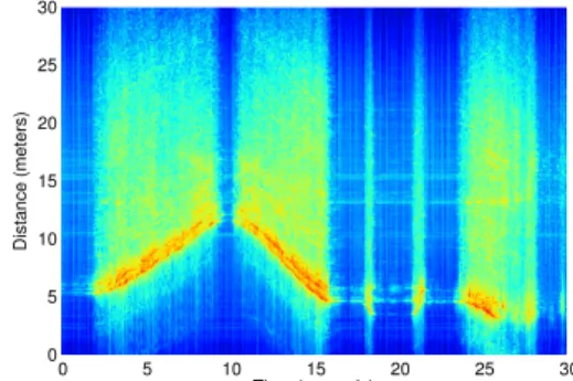
Figure 3—Obtaining the Time-of-Flight (TOF) Estimates. WiTrack takes an FFT of the received signal in baseband over every sweep period to generate the spectrogram in (a). Then, by subtracting out a given frame from the frame that precedes it, WiTrack eliminates static multipath as in (b). The blue plot in (c) shows how WiTrack can address dynamic multipath by tracking the bottom contour of (b), and then denoise the signal (red plot) to obtain a clean TOF estimate.
and sweep its carrier frequency across a wide bandwidth of multiple GHz.
In our design we chose the following parameter for our FMCW. We have built an FMCW system that sweeps a total bandwidth of 1.69 GHz from 5.56 GHz to 7.25 GHz, and transmits at 0.75 milliwatt. The choice of this band-width has been dictated by the FCC regulations for civil-ian use of spectrum [9]. Specifically, it is the largest con-tiguous bandwidth below 10 GHz which is available for civilian use at low power.
Based on Eq. 3, our sweep bandwidth allows us to obtain a distance resolution of 8.8 cm. Hence the aver-age error in mapping TOF to distance in 1D is about 4.4 cm. Note that the above derivation neglects the im-pact of noise, and hence provides a lower bound on the achievable resolution. In practice, the system’s resolution is affected by the noise level. It also depends on the geo-metric model that maps TOFs to 3D locations.
3.2 Addressing Static Multi-path
The next step in WiTrack’s operation is to distinguish a human’s reflections from reflections off other objects in the environment, like furniture and walls. Recall from the previous section that every reflector in the environ-ment contributes a component to the overall received sig-nal, and that component has a frequency shift that is lin-early related to the time-of-flight of the reflection based on Eq. 1. Typically, reflections from walls and furniture are much stronger than reflections from a human, especially if the human is behind a wall. Unless these reflections are removed, they would mask the signal coming from the human and prevent sensing her motion. This behavior is called the “Flash Effect”.
To remove reflections from all of these static objects (walls, furniture), we leverage the fact that since these reflectors are static, their distance to the WiTrack device does not change over time, and therefore their induced fre-quency shift stays constant over time. Fig. 3(a) plots the spectrogram of the received signal as a function of time, for one of the receive antennas of WiTrack. In particular,
we take the FFT of the received signal every sweep win-dow, and compute the power in each frequency as a func-tion of time. Note that there is a linear relafunc-tion between frequency shifts and the traveled distances as follows:
distance= C × TOF = C × ∆f
slope. (4)
Thus, instead of plotting the power in each frequency as a function of time, we can use the above equation to plot the power reflected from each distance as a function of time, as shown in Fig. 3(a). The color code of the plot corre-sponds to a heat-map of the power in the reflected signal. Strong reflectors are indicated by red and orange colors, weaker reflectors are indicated by yellow and green, and the absence of a reflector is indicated by blue at the corre-sponding frequency. The figure indicates the presence of very strong static reflectors in the environment. Specifi-cally, it has many horizontal stripes; each of these stripes signifies the presence of a reflector at the corresponding round-trip distance. Because these stripes are horizontal, their corresponding reflectors are stationary over time. Hence, we eliminate the power from these static reflec-tors by simply subtracting the output of the FFT in a given sweep from the FFT of the signal in the previous sweep. This process is called background subtraction because it eliminates all the static reflectors in the background.
Fig. 3(b) is the result of applying background subtrac-tion to Fig. 3(a). The figure shows that all static reflec-tors corresponding to the horizontal lines have been elim-inated. This makes it easier to see the much weaker reflec-tions from a moving human. Specifically, we see that the distance of the dominant reflector (the red color signal) is varying with time, indicating that the reflector is moving.
3.3 Addressing Dynamic Multi-path
By eliminating all reflections from static objects, WiTrack is left only with reflections from a moving hu-man (see Fig. 3(b)). These reflections include both signals that bounce off the human body to the receive antennas, and those that bounce off the human then bounce off other
objects in the environment before reaching WiTrack’s an-tennas. We refer to these indirect reflections as dynamic multi-path. It is quite possible that a human reflection that arrives along an indirect path, bouncing off a side wall, is stronger than her direct reflection (which could be severely attenuated after traversing a wall) because the former might be able to avoid occlusion.
Our idea for eliminating dynamic multi-path is based on the observation that, at any point in time, the direct signal reflected from the human to our device has trav-elled a shorter path than indirect reflections. Because dis-tance is directly related to TOF, and hence to frequency, this means that the direct signal reflected from the hu-man would result in the smallest frequency shift among all strong reflectors after background subtraction.
We can track the reflection that traveled the shortest path by tracing the bottom contour of all strong reflec-tors in Fig. 3(b). The bottom contour can be defined as the closest local maximum to our device. To determine the first local maximum that is caused by human motion, we must be able to distinguish it from a local maximum due to a noise peak. We achieve this distinguishability by averaging the spectrogram across multiple sweeps. In our implementation, we average over five consecutive sweeps, which together span a duration of 12.5 ms. For all prac-tical purposes, a human can be considered as static over this time duration; therefore, the spectrogram would be consistent over this duration. Averaging allows us to boost the power of a reflection from a human while diluting the peaks that are due to noise. This is because the human reflections are consistent and hence add up coherently, whereas the noise is random and hence adds up incoher-ently. After averaging, we can determine the first local maximum that is substantially above the noise floor and declare it as the direct path to the moving human.
The blue plot in Fig. 3(c) shows the output of WiTrack’s contour tracking of the signal in Fig. 3(b). In practice, this approach has proved to be more robust than tracking the dominant frequency in each sweep of the spectrogram. This is because, unlike the contour which tracks the clos-est path between a human body and WiTrack’s antennas, the point of maximum reflection may abruptly shift due to different indirect paths in the environment or even ran-domness in the movement of different parts of the human body as a person performs different activities.
3.4 Dealing with Noise
After obtaining the bottom contour of the spectrogram of the signal from each receive antenna, WiTrack lever-ages common knowledge about human motion to miti-gate the effect of noise and improve its tracking accuracy. Specifically, by performing the following optimizations, we obtain the red plot in Fig. 3(c):
• Outlier Rejection: WiTrack rejects impractical jumps in distance estimates that correspond to unnatural
hu-man motion over a very short period of time. For ex-ample, in Fig. 3(c) , the distance from the reflector (the blue line) repeatedly jumps by more than 5 meters over a span of few milliseconds. Such changes in distance are not possible over such small intervals of time, and hence WiTrack rejects such outliers.
• Interpolation: WiTrack uses its tracking history to lo-calize a person when she stops moving. In particular, if a person walks around in a room then sits on a chair and remains static, the background-subtracted signal would not register any strong reflector. In such scenarios, we assume that the person is still in the same position and interpolate the latest location estimate throughout the period during which we do not observe any motion, en-abling us to track the location of a subject even after she stops moving.
• Filtering: Because human motion is continuous, the variation in a reflector’s distance to each receive an-tenna should stay smooth over time. Thus, WiTrack uses a Kalman Filter to smooth the distance estimates.
4
L
OCALIZING IN3D
After contour tracking and de-noising of the estimate, WiTrack obtains a clean estimate of the distance travelled by the signal from the transmit antenna to the human re-flector, and back to one of the receive antennas. Let us call this estimate the round trip distance. At any time, there are three such round trip distances that correspond to the three receive antennas. The goal of this section is to use these three estimates to identify the 3D position of the human, for each time instance.
To do so, WiTrack leverages its knowledge of the place-ment of the antennas. Recall that the antennas are placed in a T, as in Fig.1(a) where the y-axis is a horizontal line orthogonal to the plane of the T and the z-axis is along its vertical line. WiTrack uses this reference frame to track the 3D location of a moving target.
Let us focus on identifying the location at a particular
time ti. Also for clarity, let us first assume that we would
like to localize the person in the 2D plane defined by the x and y axes. Consider the transmit antenna and the first receive antenna. WiTrack knows the round trip distance from the transmit antenna to the person and back to the first receive antenna. The region of feasible 2D locations for the target need to satisfy this constraint; hence, they fall on the periphery of an ellipse, whose foci are collo-cated with the Tx and Rx1 antennas and its major axis is equal to the round trip distance. Now consider the second receive antenna. WiTrack knows the round trip distance from the Tx to the person and back to Rx2. Similarly, the feasible solutions to this constraint in 2D are on the pe-riphery of another ellipse whose foci are collocated with the Tx and Rx2 antennas and its major axis is equal to the round trip distance to Rx2. Since the correct location is on both ellipses, it is one of the intersection points, as
Tx
Rx1 Rx2
Invalid (outside beam) d1
Valid (within beam)
(a) 2D Localization
(b) 3D Localization
Figure 4—WiTrack’s Localization Algorithm. The TOF estimate from a receive antenna defines an ellipse whose foci are the transmit antenna and the receive antenna. (a) shows that WiTrack can uniquely localize a person using the intersection of two ellipses. (b) shows that in 3D, the problem translates into an intersection of three ellipsoids. shown in Fig. 4(a). In fact, since our antennas are direc-tional, only one of the two intersection points is feasible, which is the one that yields a location in the direction of the antennas beams.
It is straightforward to generalize the argument to lo-calizing in 3D. Specifically, in a 3D space, the round-trip distance defines an ellipsoid whose two foci are the trans-mit antenna and one of the receive antennas. In this set-ting, the intersection of two ellipsoids would define an arc in the 3D space, and hence is insufficient to pinpoint the 3D location of a person. However, by adding a third direc-tional antenna, we obtain a unique solution in 3D that is within the beam of all the directional antennas as shown in Fig. 4(b). Therefore, our algorithm can localize a person in 3D by using three directional receive antennas.
Finally we note two points:
• The T-shape placement for the antennas is chosen cause we assume the user wants to localize motion be-hind a wall, in which case all the antennas would have to be arranged in one plane facing the wall. We place one antenna below to help determine elevation, while the others are on the same level.
• While the minimum number of Rx antennas necessary to resolve a 3D location is three, adding more anten-nas would result in more constraints. This would allow us to over-constrain the solution and hence add extra robustness to noise.
5
B
EYOND3D T
RACKINGIn this section, we build on WiTrack’s 3D localization primitive to enable two additional capabilities: estimating
0 5 10 15 20 25 30 Time (seconds) 0 5 10 15 20 25 30 Distance (meters)
Figure 5—Gestures. The figure shows a human moving then stopping and pointing with her arm. The small bright regions around t = 18s and
t= 21s correspond to the arm lifting and dropping motions.
a pointing direction from the corresponding arm move-ment, and detecting a fall.
5.1 Estimation of Pointing Angle
We explain how WiTrack provides coarse estimation of body part motion. We consider the following motion: the user starts from a state where her arm is rested next to her body. She raises the arm in a direction of her choice with the intention of pointing toward a device or appliance, and then drops her hand to the first position. The user may move around and at a random time perform the pointing gesture. We require, however, that the user be standing (i.e., not walking) when performing the pointing gesture. The goal is to detect the pointing direction.
To track such a pointing gesture, WiTrack needs to dis-tinguish between the movement of the entire body and the motion of an arm. To achieve this goal, we leverage the fact that the reflection surface of an arm is much smaller than the reflection surface of an entire human body. We estimate the size of the reflection surface from the spec-trogram of the received signal at each of the antennas. Fig. 5 illustrates the difference between the spectrogram of a whole body motion and that of an arm pointing, as captured by one of WiTrack’s receiving antennas. In the figure the human was moving then stopped and performed the pointing gesture. The two bright spots around t = 18s and t = 21s refer to the arm being lifted and dropped re-spectively. The figure shows that the signal variance along the vertical axis is significantly larger when the reflector is the entire human body than when it is just an arm motion (note the bright yellow as opposed to the cyan color). If the reflector is large, its parts have slightly different posi-tions from each other; hence, at any point in time the vari-ance of its reflection along the y-axis is larger than that of an arm movement. WiTrack uses this spatial variance to detect body part motion from a whole body motion.
Once we detect it is a body part, WiTrack tries to esti-mate the direction of the motion to identify the pointing direction, which involves the following steps:
1. Segmentation: The goal of segmentation is to deter-mine the start and end of a pointing gesture. Fig. 5 shows how WiTrack segments the round trip distance spectrogram obtained from each receive antenna. In
our pointing experiments, we ask the user to remain static for a second before performing the pointing ges-ture. Thus, we are able to detect the start of a pointing gesture since it is always preceded by a period of ab-sence of motion. Similarly, after a person raises her arm in a pointing direction, we ask her to wait for a second before resting her arm back to its initial po-sition. Because WiTrack performs a frequency sweep every 2.5 ms, we can easily distinguish the silence at the start and end of a gesture.
2. Denoising: As is the case for a whole body motion, the contour of the segmented spectrogram is denoised and interpolated (see §3.4) to obtain a clean estimate of the round trip distance of the arm motion as a function of time, for each receive antenna.
3. Determining the Pointing direction: We perform ro-bust regression on the location estimates of the mov-ing hand, and we use the start and end points of the regression from all of the antennas to solve for the ini-tial and final position of the hand. WiTrack estimates the direction of pointing as the direction from the ini-tial state to the final extended state of the hand. Since the user drops her hand after pointing, WiTrack repeats the above steps for this drop motion obtaining a second estimate of the pointing direction. Then, WiTrack es-timates the pointing direction as the middle direction
between the two.3Being able to leverage the
approxi-mate mirroring effect between the arm lifting and arm dropping motions adds significant robustness to the es-timation of the pointing angle.
We envision that an application of the estimation of pointing direction can be to enable a user to control house-hold appliances by simply pointing at them. Given a list of instrumented devices and their locations, WiTrack would track the user’s hand motion, determine the direction in which she points, and command the device to change its mode (e.g., turn on or off the lights, or control our blinds). Finally, to demonstrate the pointing gesture within the context of an application, we created a setup where the user can control the operation mode of a device or appli-ance by pointing at it. Based on the current 3D position of the user and the direction of her hand, WiTrack automat-ically identifies the desired appliance from a small set of appliances that we instrumented (lamp, computer screen, automatic shades). Our instrumentation is a basic mode change (turn on or turn off). WiTrack issues a command via Insteon home drivers [2] to control the devices. We en-vision that this setup can evolve to support a larger set of functionalities and be integrated within a home automa-tion systems [16].
5.2 Fall Detection
Our objective is to automatically distinguish a fall from other activities including sitting on the ground, sitting on
3by zooming on Fig. 5 the reader can see how the arm lifting and
dropping motions approximately mirror each other’s tilt.
0 0.5 1 1.5 2 0 5 10 15 20 25 30
Elevation (in meters)
Time (in seconds) Walk
Sit on Chair Sit on Ground Fall
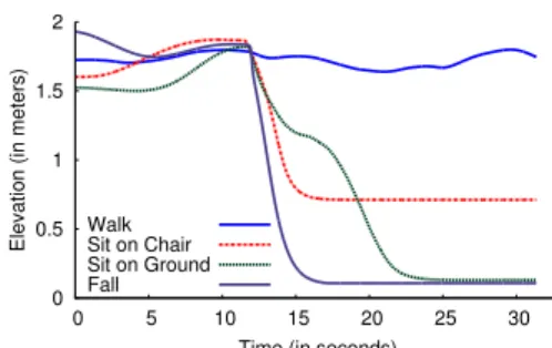
Figure 6—Fall Detection. WiTrack automatically detects falls by mon-itoring the absolute value and the change in elevation.
Phase#Frequency# Detector# VCO# Digital# Synthesizer# Frequency# Divider# BandPass#Filter# Amp# X# HighPass# Filter# USRP# LNA# Tx# Rx1# Signal#Genera1on# Rxn#
Figure 7—Schematic of the Front End Design. WiTrack’s front end consists of an FMCW signal generation component, and a receive chain that is connected to a USRP.
a chair and walking. To do so, we build on WiTrack’s ele-vation tracking along the z dimension. Note that simply checking the person’s elevation is not sufficient to dis-tinguish falls from sitting on the floor. To detect a fall, WiTrack requires two conditions to be met: First, the per-son’s elevation along the z axis must change significantly (by more than one third of its value), and the final value for her elevation must be close to the ground level. The second condition is the change in elevation has to oc-cur within a very short period to reflect that people fall quicker than they sit.
Fig. 6 plots WiTrack’s estimate of the elevation along the z dimension for four activities: a person walking, sit-ting on a chair, sitsit-ting on the ground, and (simulated)
falling on the ground.4The figure confirms that walking
and sitting on a chair can be identified from falling and sitting on the floor based on elevation because the final el-evation is far from z = 0. However, to distinguish a fall on the ground from a sitting on the ground, one has to exploit that during a fall the person changes her elevation faster than when she voluntarily sits on the floor.
6
I
MPLEMENTATIONFMCW Radio Front-End Hardware: We have built an FMCW front-end that operates as a daughterboard for the USRP software radio [5]. Below, we describe our design, which is illustrated in the schematic of Fig. 7.
The first step of our front end design is the genera-tion of an FMCW signal, which consists of a narrowband signal whose carrier frequency is linearly swept over a large bandwidth. This signal can be obtained by using
a voltage-controlled oscillator (VCO). Because the out-put frequency of a VCO is a linear function of its inout-put voltage, we can generate our desired frequency sweep by feeding a voltage sweep as an input to the VCO. How-ever, small errors in the input voltage can create large non-linearities in the output sweep.
To obtain a highly linear sweep, we use a feedback mechanism. Specifically, we use a phase frequency de-tector to compare the output frequency of the VCO with a highly accurate reference signal, and use the offset be-tween the two to control the VCO. Note that even though the reference signal needs to be highly accurate, it does not need to span the same bandwidth as our desired out-put signal. In particular, rather than directly comparing the output of the VCO to the reference signal, we first use a frequency divider. This allows us to use a reference signal that sweeps from 136.5–181.25 MHz to generate an FMCW signal that sweeps from 5.46–7.25 GHz. This FMCW signal is transmitted over the air using WA5VJB directional antennas [7] after filtering and amplification.
At the receive chain, the transmitted signal is captured using WA5VJB directional antennas and passed through a low-noise amplifier and a high-pass filter to improve its SNR. Recall from §3 that an FMCW receiver determines the TOF by measuring the frequency offset between the transmitted and the received signal. This offset can be obtained by downconverting (mixing) the received sig-nal with the transmitted sigsig-nal. The output of the mixer is then fed to the LFRX-LF daughterboard on USRP2 which samples it at 1 MHz and passes the digitized samples to the UHD driver.
Real-time Software Processing: The implemented pro-totype performs real-time 3D motion tracking as de-scribed in §3, §4 and §5. Tracking is implemented di-rectly in the UHD driver of the USRP software radio. The signal from each receiving antenna is transformed to the Frequency domain using an FFT whose size matches the FMCW sweep period of 2.5ms. To improve resilience to noise, every five consecutive sweeps are averaged creat-ing one FFT frame. Background subtraction is performed by subtracting the averaged FFT frame from the frame that precedes it. The spectrogram is processed for contour tracking by identifying for each time instance the small-est local frequency maximum that is significantly higher than the noise level. Outlier rejection is performed by declaring that the contour should not jump significantly between two successive FFT frames (because a person cannot move much in 12.5ms). The output is smoothed with a Kalman filter.
To locate a person, instead of solving a system of el-lipsoid equations in real-time, we leverage that the loca-tion of the antennas does not change and is known a pri-ori. Thus, before running our experiments, we use MAT-LAB’s symbolic library to find a symbolic representation
of the solutions (x, y, z) as a function of symbolic TOF to each of the receiving antennas. This means that the ellip-soid equations need to be solved only once (for any fixed antenna positioning), independent of the location of the tracked person. After it obtains the 3D location of a per-son, WiTrack uses python’s matplotlib library to output this location in real-time.
Software processing has a total delay less than 75 ms between when the signal is received an a corresponding 3D location is output.
7
E
VALUATIONWe empirically evaluate the performance of the WiTrack prototype by conducting experiments in our lab building with 11 human users.
(a) Ground Truth: We determine WiTrack’s localization accuracy by testing it against the VICON motion capture system. The VICON is a multi-hundred-thousand dollar system used in filmmaking and video game development to track the human motion and map it to a 3D charac-ter animation model. It uses calibrated infrared cameras and records motion by instrumenting the tracked body with infrared-reflective markers. The VICON system has a sub-centimeter accuracy and hence we use it to deter-mine the ground truth location. To track a moving person with the VICON, she is asked to wear a jacket and a hat, which are instrumented with eight infrared markers. To track a subject’s hand, she is asked to wear a glove that is also instrumented with six markers. The VICON tracks the infrared markers on the subject’s body and fits them to a 3D human model to identify the subject’s location.
The VICON system has a built-in capability that can track the center of any object using the infrared-reflective markers that are placed on that object. This allows us to determine the center position of a human subject who is wearing the instrumented jacket and hat. WiTrack how-ever computes the 3D location of the body surface where the signal reflects. In order to compare WiTrack’s mea-surements to those obtained by the VICON, we need to have an estimate of the depth of the center with respect to the body surface. Thus, we use the VICON to run of-fline measurements with the person standing and having infrared markers around her body at the same height as the WiTrack transmit antenna (about the waist). We use the VICON to measure the average depth of the center from surface for each person. To compare the 3D location computed by the two systems, we first compensate for the average distance between the center and surface for that person and then take the Euclidean distance.
(b) Device Setup: WiTrack is placed behind the wall of the VICON room. The device uses one transmit antenna and three receive antennas. The transmit antenna and two receive antennas are lined up parallel to the wall, and a third receive antenna is placed below the transmit antenna. The distance between the transmit antenna and each
0 0.2 0.4 0.6 0.8 1 0 20 40 60 80 100 Fraction of measurements
Location Error (in centimeters) x dimension y dimension z dimension (a) CDF in line-of-sight 0 0.2 0.4 0.6 0.8 1 0 20 40 60 80 100 Fraction of measurements
Location Error (in centimeters) x dimension y dimension z dimension
(b) CDF through-wall
Figure 8—Performance of WiTrack’s 3D Tracking. (a) and (b) show the CDF of the location error for WiTrack in line-of-sight and through-wall scenarios respectively.
ceive antenna is 1m, unless otherwise noted.
(c) Human Subjects: The experiments are performed with eleven human subjects: two females and nine males. The subjects are of different heights and builds, and span an age range of 22 to 56 years. In each experiment, the subject is asked to move at will in the VICON room; he/she is tracked using both the VICON system and WiTrack. Note that WiTrack tracks the subject through the wall, from an adjacent room, while the VICON has to be within direct line of sight from the subject.
8
P
ERFORMANCER
ESULTS8.1 Accuracy of 3D Tracking
We first focus on the developed 3D tracking primitive and evaluate its accuracy across all three dimensions.
We run 100 experiments each lasting for 1 minute, dur-ing which a human subject moves at will in the VICON room. The VICON room has no windows. It has 6-inch hollow walls supported by steel frames with sheet rock on top, which is a standard setup for office buildings. The WiTrack prototype is placed outside the room with all transmit and receive antennas facing one of the walls of the VICON room. Recall that WiTrack’s antennas are di-rectional; hence, this setting means that the radio beam is directed toward the wall of the VICON room. In each ex-periment, we ask the subject to wear the jacket and hat that were instrumented with VICON markers and move inside the VICON-instrumented room. The subject’s location is tacked by both the VICON system and WiTrack.
We note that the VICON IR cameras are set to
accu-rately track the target only when she moves in a 6 × 5 m2
area in the room. Their accuracy degrades outside that area. Since VICON provides the ground truth in our
ex-periment, we ask the target to stay within the 6 × 5 m2
area where the IR cameras are focused. This area is about 2.5m away from the wall. Thus, the minimum separation between WiTrack and the human subject in these experi-ments is 3 m and the maximum separation is about 9 m.
We perform a total of 100 experiments for this eval-uation, each lasting for one minute. Since each FMCW sweep lasts for 2.5ms and we average 5 sweeps to obtain for each TOF measurement, we collect a total of about 480,000 location readings from these 100 experiments.
To show that WiTrack works correctly both in line of
sight and through a wall, we repeat the above 100 ex-periments with one modification, namely we move the WiTrack device inside the room and set it next to the wall from the inside.
Fig. 8(a) and Fig. 8(b) plot the CDFs of the location error along the x, y, and z coordinates. The figure reveals the following findings:
• WiTrack’s median location error for the line-of-sight experiments is 9.9 cm, 8.6 cm, and 17.7 cm along the x, y, and z dimensions respectively. In comparison, the median location error in the through-wall experiments is 13.1 cm, 10.25 cm, and 21.0 cm along the x, y, and z dimensions. As expected the location accuracy in line-of-sight is higher than when the device is behind a wall due to the extra attenuation and the reduced SNR. In both cases, however, the median error is fairly small. This is due to the use of an FMCW radio which en-sures a highly accurate TOF estimate, and the ability to prevent errors due to multipath and noise, allowing the system to stay accurate as it moves from TOF to a 3D location estimate of the human body.
• Interestingly, the accuracy in the y dimension is better than the accuracy in the x dimension. This difference is because the x and y dimensions are not equal from the perspective of WiTrack’s antennas. Recall that in the xy-plane, WiTrack’s antennas are all along the x-axis. As a result, the two ellipses in the xy-plane, shown in Fig. 8, both have their major radius along x and minor radius along y. Hence, the same error in TOF produces a bigger component when projected along the x axis than along the y axis.
• The accuracy along the z-dimension is worse than the accuracy along the x and y dimensions. This is the re-sult of the human body being larger along the z dimen-sion than along x or y.
8.2 Accuracy Versus Distance
We are interested in evaluating WiTrack’s accuracy as the person gets further away from the device. Thus, we re-peat the above through-wall experiments. As mentioned above, VICON requires the human to move in a certain space that is in line of sight of the IR cameras. Thus, to increase the distance from WiTrack to the human we move WiTrack away in the hallway next to the VICON
0 10 20 30 40 50 1 2 3 4 5 6 7 8 9 10 11
Localization Error (in centimeters)
Distance from transmitter (in meters) Median
90th Percentile
(a) Accuracy in x-dimension
0 5 10 15 20 25 30 1 2 3 4 5 6 7 8 9 10 11
Localization Error (in centimeters)
Distance from transmitter (in meters) Median 90th Percentile (b) Accuracy in y-dimension 0 10 20 30 40 50 60 70 80 1 2 3 4 5 6 7 8 9 10 11
Localization Error (in centimeters)
Distance from transmitter (in meters) Median
90th Percentile
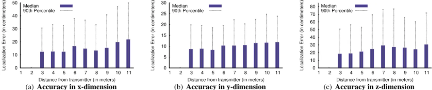
(c) Accuracy in z-dimension Figure 9—3D Localization Accuracy Versus Distance to Device. (a)-(c) show the location error along the x, y, and z dimensions as a function of
how far the subject is from WiTrack. The median and 90thpercentile errors increase as the distance from the device to the person increases.
0 10 20 30 40 50 60 70 0 0.25 0.5 0.75 1 1.25 1.5 1.75 2
Localization Error (in centimeters)
Antenna Separation (in meters) Median 90th Percentile
(a) Accuracy in x-dimension
0 5 10 15 20 25 30 35 40 0 0.25 0.5 0.75 1 1.25 1.5 1.75 2
Localization Error (in centimeters)
Antenna Separation (in meters) Median 90th Percentile (b) Accuracy in y-dimension 0 20 40 60 80 100 120 0 0.25 0.5 0.75 1 1.25 1.5 1.75 2
Localization Error (in centimeters)
Antenna Separation (in meters) Median 90th Percentile
(c) Accuracy in z-dimension
Figure 10—3D Localization Accuracy Versus Size of Device. (a)-(c) show the median and 90thpercentile location errors as a function of the
antenna separation. Along all three dimensions, a larger separation leads to a decrease in the location error. room. Again, we collect 100 experiments, each spanning
one minute for a total of 480,000 location measurements. Fig. 9 plots WiTrack’s localization error as a function of its distance to the subject. The distance to the subject is determined using the VICON ground-truth coordinates, and rounded to the nearest meter. The figure shows the
median and 90thpercentile of the estimation error for the
x, y, and z coordinates.
The figure shows that the median accuracy changes by 5 to 10 cm for distances that are 3 to 11 m away from the device. As expected, the further the human moves from the device, the larger the estimation error. This increase in error with distance is expected since as the distance gets larger the signal gets more attenuated. However, a second reason stems from the geometry of the ellipsoid-based localization model. Given the equations of the el-lipsoid, the TOF multiplied by the speed of light is equal to the major axis of the ellipsoid/ellipse that describes the user’s location, and the antenna separation is the distance between the foci. For a fixed antenna separation, as the distance/TOF increases the ellipsoid’s surface increases, increasing the overall space of potential locations.
The figure also shows that the accuracy is best along the y dimension, then the x, and finally the z, which is due to the reasons discussed in the previous section.
8.3 Accuracy Versus Antenna Separation
Our default setting places the receive antennas 1 m away from the transmit antenna. In this section, we ex-amine the impact of antenna separation on performance.
We evaluate five different configurations. In all of these configurations, the transmit antenna is at an equal distance from all receive antennas, and is placed at the crossing
point of a “T” whereas the receive antennas are placed at the edges. We vary the distance between the transmit antenna and each of the receive antennas from 25 cm to 2 m. We run 100 one-minute experiments, 20 for each antenna setting. All experiments are run through a wall. In each experiment, we ask the human subject to move at will inside the VICON room, as we record her location using both the VICON system and WiTrack.
Fig. 10 shows WiTrack’s localization accuracy as a function of antenna separation. The figure shows that even if one brings the antennas to within 25cm of each other, the median location error stays less than 17 cm, 12 cm,
and 31 cm for the x, y, and z dimensions, and 90th
per-centile becomes 64cm, 35cm, and 116cm respectively. While this is higher than the previous results where the antennas were separated by 1 m, it is still comparable to state of the art localization using a WiFi transmitter (in our case, the user does not need to carry any wireless device). The plots show that as the antenna separation increases, the localization accuracy improves along all three dimen-sions x, y, and z. This behavior is expected, because the further the receive antennas are from each other, the larger the spatial diversity between them. Because of the geo-metric nature of the algorithm, a spatially diverse setup would lead to a smaller intersection curve between any
pair of ellipsoids.5For this reason, in a larger setup, the
5For simplicity, consider the 2D case with 1 Tx and 2 Rx antennas.
Because of the system’s resolution, each ellipse has some fuzzy region about it (i.e., a thickness of +/ε, where ε is determined by the resolu-tion). Thus, the intersection of two ellipses is a region rather than a sin-gle point. This region becomes larger when the Rx antennas are closer to each other, and the larger the region, the larger the ambiguity in localiza-tion. In the extreme case where the two receive antennas are co-located,
same noise variance in the TOF estimates would be con-fined to a smaller curve, thus, minimizing estimate error.
Mathematically, for any TOF, the antenna separation is the distance between the foci of the ellipsoid that defines the person’s location. Hence for any given TOF, increas-ing the antenna separation increases the distance between the foci while keeping the ellipsoid’s major radius con-stant. Hence the ellipsoid gets more squashed and its cir-cumference becomes smaller, reducing the region of po-tential solutions.
8.4 Accuracy of Estimating Pointing Direction
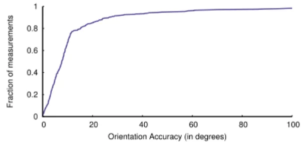
In the experiments in this section, the human subjects wear a glove that is instrumented with infrared reflexive markers, and are asked to stand in a given location in-side the VICON room and point in a direction of their choice. Each pointing gesture consists of raising the sub-ject’s hand in the direction of her choice, followed by the subject returning her hand to its original resting position. Across our experiments, we ask the human subjects to stand in random different locations in the VICON room and perform the pointing gesture. We determine the di-rection in which the subject pointed by using both the VI-CON recordings and WiTrack’s estimates (see §5.1).
Fig. 11 plots a CDF of the error between the angle as determined by WiTrack and the ground truth angle based on the VICON measurements. The figure shows that the median orientation error is 11.2 degrees, and the
90thpercentile is 37.9 degrees. These results suggest that
WiTrack provides an enabling primitive to track pointing gestures. We used this capability to enable controlling dif-ferent household appliances like shades, lamps and com-puter screens by sending commands to these different ap-pliances over Insteon drivers.
8.5 Fall Detection
We test the fall detection algorithm described in §5.2 by asking different participants to perform four different activities: walk, sit on a chair, sit on the floor, and simulate a fall. The floor of the VICON room is already padded. We add extra padding to ensure no injury can be caused by simulated falls. We perform 132 experiments in total, 33 for each activity. We log the data files from each of these experiments and process them offline with our fall detection algorithm. We obtain the following results: • None of the walking or sitting on a chair activities are
classified as falls.
• One of the sitting on the floor experiments was classi-fied as a fall.
• Two out of 33 simulated falls were not detected (they were misclassified as sitting on the ground).
Thus, the precision of the fall detection algorithm is 96.9% (since out of the 32 detected falls only 31 are true falls) , and the recall is 93.9% (since out of 33 true falls we detected 31). This yields an F-measure of 94.4%. the two ellipses perfectly overlap and the ambiguity region is large.
0 0.2 0.4 0.6 0.8 1 0 20 40 60 80 100 Fraction of measurements
Orientation Accuracy (in degrees)
Figure 11—Orientation Accuracy. The CDF of the orientation
accu-racy shows that the median orientation error is 11.2 degrees, and the 90th
percentile error is 37.9 degrees.
9
R
ELATEDW
ORKIndoor wireless localization: WiTrack builds on recent advances in RF-based localization [31, 18, 28, 11]. These systems localize a wireless device using RSSI [11, 22], fine-grained-OFDM channel information [25], antenna arrays [31, 18], or RFID backscatter [28, 27]. In contrast, WiTrack localizes a human using body radio reflections.
Some past works in radio tomography use a network of tens or hundred sensors to track a person even if she does not carry any wireless device [29, 30]. These works
mea-sure the RSSI for each of the resulting n2links between
their sensors, and attribute the variation of RSSI on a link to a human crossing that link. Other works on device-free localization rely on RSSI fingerprints [32, 24], which are generated in a training phase by asking a person to stand in different locations throughout the area of interest. In the testing phase, they localize a person by mapping the resulting RSSI to the closest fingerprint. While WiTrack shares the objective of tracking a person’s motion with-out instrumenting her body, it differs in both technology and accuracy. Specifically, WiTrack does not require prior training and uses a few antennas that generate FMCW sig-nals and measure the time-of-flight of the signal reflec-tions to infer location of a human. Its technique extends to 3D, and its 2D accuracy is more than 5× higher than the state of the art RSSI-based systems [33, 24].
See through-wall & gesture recognition using WiFi: WiTrack is motivated by recent research that used WiFi signals to detect users through walls and identify some of their gestures [10, 21, 13]. Similar to these systems, WiTrack captures and interprets radio reflections off a hu-man body. WiTrack, however, differs from these systems both in capability and technology. Specifically, these sys-tems rely on the Doppler shift of WiFi signals. Hence, they can distinguish only between getting closer or get-ting further away, but cannot identify the location of the
person.6In contrast, WiTrack measures the time of flight
and, hence, can identify the exact location of a person. Among these past systems, WiVi [10] focuses on
track-6The gestures recognized by WiVi and WiSee are sequences of
get-ting closer or getget-ting further away, which translate into positive and neg-ative Doppler shifts. The work in [13] provides a distance estimate with an accuracy of about 30 meters.
ing through dense walls such as concrete by leveraging interference nulling to eliminate the wall’s reflection. In contrast, WiTrack focuses on accurate 3D motion track-ing that operates through interior walls (which are less
dense than concrete)7, pinpointing the exact location of a
user at any point in time.
FMCW Radar: WiTrack builds on past work on FMCW radar, including work that used FMCW for see-through-wall that is targeted for the military [23, 12]. WiTrack however differs along multiple dimensions. First, FMCW radios in past work were high-power and heavy (needed to be mounted on a truck). Their tracking capabilities hinge on using large antenna arrays that can achieve a narrow beam, which enables tracking a moving target. In con-trast, we present a light weight, low-power FMCW ra-dio that complies with the FCC regulations for consumer devices. We are able to perform accurate tracking with a low-power, relatively cheap FMCW prototype because of two innovations: first, a geometric localization algo-rithm that combines multiple measurements from differ-ent antenna locations and fits them within a geometric ref-erence to pinpoint an accurate 3D location, and second, novel techniques that enable rejecting errors that are due to both static and dynamic multi-path in indoor environ-ments. Further, WiTrack extends its techniques to tracking the motion of body parts, e.g., tracking a hand as it points in a particular direction.
Motion tracking in user interfaces: Finally, WiTrack is related to an emerging body of motion-tracking user inter-faces. These include devices that the person needs to hold (such as the Nintendo Wii [4]) or wear (e.g., on-body sen-sors such as wristbands [1, 14, 17]). They also include vision and infrared-based systems, like Xbox Kinect [8] and Leap Motion [3], which can track a person’s move-ment without requiring her to hold or wear any transmitter or receiver but require the user to maintain a line-of-sight path to their sensors. Similar to these systems, WiTrack enables more natural human-computer interaction. How-ever, in comparison to these systems, WiTrack does not require the user to hold/wear any device or to maintain a line-of-sight path to its sensors; it can track a user and her gestures in non-line-of-sight and across different rooms.
10
L
IMITATIONS& C
ONCLUSION3D motion tracking based purely on RF reflections off a human body is a challenging technical problem. We be-lieve WiTrack has taken an important step toward address-ing this problem. However, the current version of WiTrack still has limitations:
Tracking one person: Our current design can track only one person at any point in time. This does not mean that WiTrack requires only one person to be present in the en-vironment. Other people can be around, but they have to
7To enable WiTrack to track through thicker walls such as concrete
(as in WiVi), one may add a filter to remove the wall’s reflection.
be behind the directional antennas. We believe that this limitation is not fundamental to the design of WiTrack and can be addressed as the research evolves. Consider for example, the case of two moving humans. In this case, each antenna has to identify two concurrent TOFs (one for each person), and hence two ellipsoids. To eliminate the ambiguity, one may use more antennas which add more constraints to the system.
Requiring motion: A second limitation stems from the fact that WiTrack needs the user to move in order to locate her. This is because WiTrack receives reflections from all static objects in the environment; hence, it cannot distin-guish the static user from a piece of furniture. To elimi-nate these static reflectors, WiTrack subtracts consecutive FMCW sweeps. Unfortunately, that eliminates the reflec-tions of the static user as well. Future research may ad-dress this issue by having WiTrack go through a training period where the device is first presented with the space without any user so that it may learn the TOFs of the static objects. Naturally, this would require retraining ev-ery time the static objects are moved in the environment. Distinguishing between body parts: Currently WiTrack can provide coarse tracking of the motion of one body part. The tracked part has to be relatively large like an arm or a leg. WiTrack however does not know which body part has moved, e.g., it cannot tell whether it is an arm or a leg. In our experiments, the users were pointing with their arms. Extending this basic capability to tracking more general movements of body parts will likely require incorporating complex models of human motion. In par-ticular, Kinect’s ability to track body parts is the result of the combination of 3D motion tracking using infrared with complex vision algorithms and advanced models of human motion [26]. An interesting venue for research is to investigate how WiTrack may be combined with these techniques to produce a highly accurate motion tracking system that operates across walls and occlusions.
While there is scope for many improvements, we be-lieve WiTrack advances the state of the art in 3D mo-tion tracking by enabling through wall operamo-tion without requiring any instrumentation of the user body. Further-more, its fall detection and pointing estimation primitives enable innovative applications.
Acknowledgments:We thank Jue Wang, Haitham Hassanieh,
Ezz Hamad, Deepak Vasisht, Mary McDavitt, Diego Cifuentes, Swarun Kumar, Omid Abari, and Jouya Jadidian for participat-ing in our experiments. We also thank Nate Kushman, Lixin Shi, the reviewers, and our shepherd, Kyle Jamieson, for their in-sightful comments. This research is supported by NSF. We thank members of the MIT Center for Wireless Networks and Mobile Computing: Amazon.com, Cisco, Google, Intel, Mediatek, Mi-crosoft, ST Microelectronics, and Telefonica for their interest and support.
R
EFERENCES[1] Fitbit Flex. http://www.fitbit.com/flex. [2] Insteon ApplianceLinc. http://www.insteon.com.
Insteon.
[3] Leap Motion. https://www.leapmotion.com. [4] Nintendo Wii. http://www.nintendo.com/wii. [5] USRP N210. http://www.ettus.com. Ettus Inc. [6] VICON T-Series. http://www.vicon.com. [7] WA5VJB antenna. http://www.wa5vjb.com. Kent
Electronics.
[8] X-box Kinect. http://www.xbox.com. Microsoft. [9] Understanding the FCC Regulations for Low-power,
Non-licensed Transmitters. Office of Engineering and Technol-ogy Federal Communications Commission, 1993. [10] F. Adib and D. Katabi. See through walls with Wi-Fi! In
ACM SIGCOMM, 2013.
[11] P. Bahl and V. Padmanabhan. RADAR: an in-building RF-based user location and tracking system. In IEEE INFO-COM, 2000.
[12] G. Charvat, L. Kempel, E. Rothwell, C. Coleman, and E. Mokole. A through-dielectric radar imaging system. IEEE Trans. Antennas and Propagation, 2010.
[13] K. Chetty, G. Smith, and K. Woodbridge. Through-the-wall sensing of personnel using passive bistatic wifi radar at standoff distances. IEEE Trans. Geoscience and Remote Sensing, 2012.
[14] G. Cohn, D. Morris, S. Patel, and D. Tan. Humantenna: using the body as an antenna for real-time whole-body in-teraction. In ACM CHI, 2012.
[15] J. Dai, X. Bai, Z. Yang, Z. Shen, and D. Xuan. Perfalld: A pervasive fall detection system using mobile phones. In IEEE PERCOM, 2010.
[16] C. Dixon, R. Mahajan, S. Agarwal, A. Brush, B. Lee, S. Saroiu, and V. Bahl. An operating system for the home. In Usenix NSDI, 2012.
[17] C. Harrison, D. Tan, and D. Morris. Skinput: appropriating the body as an input surface. In ACM CHI, 2010. [18] K. Joshi, S. Hong, and S. Katti. Pinpoint: Localizing
inter-fering radios. In Usenix NSDI, 2013.
[19] B. R. Mahafza. Radar systems analysis and design using MATLAB. Chapman & Hall, 2013.
[20] N. Noury, A. Fleury, P. Rumeau, A. Bourke, G. Laighin, V. Rialle, and J. Lundy. Fall detection-principles and meth-ods. In IEEE EBMS, 2007.
[21] Q. Pu, S. Jiang, S. Gollakota, and S. Patel. Whole-home gesture recognition using wireless signals. In ACM Mobi-Com, 2013.
[22] A. Rai, K. K. Chintalapudi, V. N. Padmanabhan, and R. Sen. Zee: zero-effort crowdsourcing for indoor local-ization. In ACM MobiCom, 2012.
[23] T. Ralston, G. Charvat, and J. Peabody. Real-time through-wall imaging using an ultrawideband multiple-input multiple-output (MIMO) phased array radar system. In IEEE ARRAY, 2010.
[24] M. Seifeldin, A. Saeed, A. Kosba, A. El-Keyi, and M. Youssef. Nuzzer: A large-scale device-free passive lo-calization system for wireless environments. IEEE Trans-actions on Mobile Computing, 2013.
[25] S. Sen, B. Radunovic, R. R. Choudhury, and T. Minka.
Spot localization using phy layer information. In ACM MobiSys, 2012.
[26] J. Shotton, T. Sharp, A. Kipman, A. Fitzgibbon, M. Finoc-chio, A. Blake, M. Cook, and R. Moore. Real-time human pose recognition in parts from single depth images. Com-munications of the ACM, 2013.
[27] J. Wang, F. Adib, R. Knepper, D. Katabi, and D. Rus. RF-Compass: Robot Object Manipulation Using RFIDs. In ACM MobiCom, 2013.
[28] J. Wang and D. Katabi. Dude, where’s my card? RFID po-sitioning that works with multipath and non-line of sight. In ACM SIGCOMM, 2013.
[29] J. Wilson and N. Patwari. Radio tomographic imaging with wireless networks. In IEEE Transactions on Mobile Com-puting, 2010.
[30] J. Wilson and N. Patwari. See-through walls: Motion tracking using variance-based radio tomography networks. In IEEE Transactions on Mobile Computing, 2011. [31] J. Xiong and K. Jamieson. ArrayTrack: a fine-grained
in-door location system. In Usenix NSDI, 2013.
[32] M. Youssef, M. Mah, and A. Agrawala. Challenges:
device-free passive localization for wireless environments. In ACM MobiCom, 2007.
[33] Y. Zhao, N. Patwari, J. M. Phillips, and S. Venkatasubra-manian. Radio tomographic imaging and tracking of sta-tionary and moving people via kernel distance. In ACM ISPN, 2013.