HAL Id: hal-00137871
https://hal.archives-ouvertes.fr/hal-00137871
Submitted on 22 Mar 2007HAL is a multi-disciplinary open access archive for the deposit and dissemination of sci-entific research documents, whether they are pub-lished or not. The documents may come from teaching and research institutions in France or abroad, or from public or private research centers.
L’archive ouverte pluridisciplinaire HAL, est destinée au dépôt et à la diffusion de documents scientifiques de niveau recherche, publiés ou non, émanant des établissements d’enseignement et de recherche français ou étrangers, des laboratoires publics ou privés.
immersion lithography at 193nm
Anne-Laure Charley, Alexandre Lagrange, Olivier Lartigue, Julia Simon,
Philippe Thony, Patrick Schiavone
To cite this version:
Anne-Laure Charley, Alexandre Lagrange, Olivier Lartigue, Julia Simon, Philippe Thony, et al.. Hyper high NA achromatic interferometer for immersion lithography at 193nm. Journal of Vacuum Science and Technology B, 2005, 23, pp.2668-2674. �10.1116/1.2135295�. �hal-00137871�
P15.4 Hyper high NA achromatic interferometer
for immersion lithography at 193nm
A.L. Charley1,4, A. Lagrange2, O. Lartigue2, J. Simon3, P. Thony3, P. Schiavone4 1
STmicroelectronics, 850 rue Jean Monnet, FR-38921 Crolles, CEDEX France Corresponding author : [email protected]
2
CEA/LETI/ DOPT/STCO, 17 rue des martyrs, 38054 Grenoble cedex, France 3
CEA/LETI/ D2NT/LLIT, 17 rue des martyrs, 38054 Grenoble cedex, France 4
CNRS/LTM, 17 rue des martyrs, 38054 Grenoble cedex, France
An apparatus for immersion interferometric lithography is described here where the interfering beams are created by illuminating a first diffraction grating followed by a second diffraction grating recombining the diffracted beams onto the photo-resist plane.
The main advantage of this system is to be achromatic: thus it is possible to use a basic commercial ArF excimer laser as the exposure source. We present here the calculations made to evaluate the different parameters that can influence the depth-of-focus in the immersion configuration.
As the set-up is mainly based on the two diffraction gratings, it matters to properly design it. The purpose of this paper is to show the optimization made on the diffraction gratings in taking into account their fabrication process since they are fabricated using the capabilities of the silicon line available in our laboratory. On one hand, calculations have been done to determine the second grating period as a function of the first grating period and the ”immersion NA”. By simply adding a fluid to a “dry” system, we will indeed be able to improve the depth of focus but not the resolution. In playing with the diffraction grating periods, we are able to benefit from the introduction of the immersion fluid. We have performed simulations in order to optimize the grating diffraction efficiency as a function of the etch depth and the fractional linewidth.
Finally we report on first results obtained with the achromatic immersion interferometer. The apparatus was used with a 193 nm GAM excimer laser to print resist patterns having a period of 100 nm with excellent contrast.
I. INTRODUCTION
As immersion lithography becomes increasingly important for next generation device fabrication, benefits and drawbacks of the introduction of an immersion fluid between the imaging optics and the wafer have to be studied. In this context, it is of high interest to be able to understand the properties of hyper high NA imaging and to do so, to have access to a technique which can mimic an industrial immersion stepper by having the possibility to tune the polarization state and numerical aperture. Interferometric lithography has proven to be a useful method to study projection imaging at high numerical aperture (NA), polarization state impact on imaging, photoresists materials and defectivity due to the introduction of water and high index fluids [1].
In two waves interference as it is in interferometric lithography, the image printed grating period Λ is given by:
NA n.sin 2. . 2
λ
θ
λ
= = Λ (1)where λ is the laser wavelength, θ half of the angle between the two beams, n the fluid refractive index and NA the numerical aperture.
In standard holographic interferometric lithography at 193 nm where the beam is split and recombined by mirrors, the image field is limited to a few microns when using a commercial ArF excimer lasers since temporal and spatial coherences of such a laser are very poor. By evaluating the variations in phase difference between the two arms as a result of variations in wavelength and incidence angle, we can define the maximum image field size beyond which the grating lines wash out. Our resolution criterion is a phase difference smaller the π/2. From ref. 2, the expression of the maximum number of resolved lines N is the following :
θ
θ
λ
λ
+∆ ∆ = 1 N (2)where ∆λ is the spectral bandwidth, ∆θ the angular width, λ the laser wavelength and θ the incidence angle.
Hence, using a typical ArF excimer laser having ∆λ ≈ 0.4 nm and ∆θ ≈ 0.4 mrad, the maximum number of grating lines achievable is N= 300 for 300-nm-period lines, 420 for 100-nm-period lines and 404 for 80-100-nm-period lines since N depends on θ, therefore on Λ. This
corresponds to field sizes of respectively 90, 42 and 32 µm which is too small to be used in practice. Since researchers have focused on the study of immersion lithography at 193 nm, several setups have been built around the world. They have been faced those laser limitations, hence the optical components have to be adapted to obtain high-contrast-fringes. This has been achieved by either playing on the laser [3, 4] with the use of solid or frequency-doubled laser or on the optical setup with the design of a high-precision compact Talbot prism lens [5]. Unfortunately such setups are not without disadvantages since they require expensive lasers and optical components difficult to fabricate. We have built up a setup that has the main advantage to be achromatic: thus, temporal coherence is irrelevant and spatial coherence limits only the depth-of-focus within which interference can be obtained. Therefore it is possible to use a basic commercial ArF excimer laser as the exposure source. The other advantage of this interferometer is that the main optical elements, namely the two diffraction gratings, are fabricated using the capabilities of the silicon line available in our laboratory. Therefore, because of the simplicity and ease of fabrication of the basic optical elements of the setup, we are free to switch to various applications such as high index fluids testing and contact holes printing in a very simple way.
In this paper we report on the design of the immersion achromatic interferometer, a tolerance study and experimental results obtained with immersion achromatic interferometer.
II. DESIGN OF THE OPTICAL SETUP
Our interferometer for 193 nm immersion lithography has been adapted from a setup studied by researchers at MIT to fabricate large area, spatially coherent gratings with periods of 100 nm at 193 nm [6, 7, 8]. It consists of two phase gratings made in optically flat fused silica substrates and a chuck that holds the resist-coated wafers. The incident laser beam is diffracted by the first diffraction grating. The zero-order beam is blocked by a metal foil and the two first-order beams are incident on the second diffraction grating that recombines them by second-order diffraction. The medium between the second diffraction grating and the resist coated wafer is filled with an index matching liquid that enables NA larger than one. The liquid used is water since it has low absorbance at 193 nm and has a refractive index of 1.44 at 193 nm [9]. Figure 1 is a schematic of our immersion lithography configuration.
This interferometer has the advantage of recording high contrast gratings in resist over an area as large as the grating diffractive area since it is not limited by the laser spatial coherence, hence it enables large exposure field. It can be used for study of printability at NA greater than 1.4 with high index liquids. For liquids with index greater than 1.56 (index of
fused silica at 193 nm), NA is limited to 1.56 because NA is limited to the lowest refractive index value between fused silica and the liquid. By turning the last diffraction grating up-side down, we can get rid off this phenomenon and benefit of the increase of refractive index whereas the refractive index difference between fused silica and the liquid becomes sufficient to provide high enough diffraction efficiency.
In this part we will calculate the periods of the two diffractive elements in order to design the optical setup to achieve numerical apertures of 0.32, 0.97, 1.2 and 1.4. In normal incidence, thanks to diffraction equations in first order, we describe the diffraction by the first grating: 1 sin sin P g g λ β γ = = (3)
And by diffraction by the second grating reached by an incident beam with an angle γg:
1 2 g 2 e e P P . 2 sin P . 2 sin . n sin . n λ λ γ λ β γ − = − = = (4)
where γg, βg,γe and βe are the angles of the +1 and -1 orders in the air gap and of the -2 and +2 orders in the water gap respectively (see figure 1).
We define here the equivalent grating pitch Q as
1 2 1 2 1 P P Q = − (5)
Q takes into account the first grating P1 that diffracts in first orders in an arbitrary direction and the second grating P2 that diffracts in second orders in the opposite direction. It can be viewed as an equivalent grating that replaces the pair P1-P2.
From the Eq. (1) we see that the final period of the resist pattern is given by
2 Q =
Λ (6)
Finally the numerical aperture of the system is equal to
Q
NA= λ (7)
From Eq. (7) the NA only depends on the equivalent grating pitch Q and can be increased by decreasing Q. The NA can reach values greater than 1 by choosing P1 and P2 so that Q
becomes smaller than the wavelength. But in the case of dry lithography, when Q<193 nm, the second-order beams present in the fused silica substrate are reflected back at the fused silica-air interface because of total internal reflection. Eq. (8) is the necessary condition on the last medium refractive index N to enable light transmission from fused silica to resist:
Q
N ≥ λ (8)
We can work with a dry system until Q reaches the wavelength value; when Q>193 nm it is mandatory to work in immersion.
Fig. 2. shows NAs for different combinations of P1 and P2. It can be seen that, for the chosen ranges of P1 and P2, NA between 0.3 and 1.8 can be achieved. Moreover, different combinations of gratings P1 and P2 can provide the same NA.
For symmetry considerations, we would like to have P1=P2=Q. But the higher the NA, the smaller the diffraction gratings periods, hence it would necessitate gratings with periods down to 193nm for NA=1. Since diffraction gratings with such periods become difficult to manufacture, it is easier to make the system asymmetrical.
Several couples of gratings was designed for achieving different NA, hence different image pitch values, as shown in table 1. In order to make the manufacturing easier an effort was put to keep a grating in common between settings, enabling minimal change to tune the NA.
III. FRINGE FORMATION ANALYSIS
In this section, a complete tolerance study is done in order to evaluate the influence of the different elements on the fringe formation. Starting from the analysis made for the achromatic holographic configuration [10], we will do a tolerance analysis for the immersion configuration. To do so, we will calculate the phase difference between the fields interfering at the top of the resist and look at its variation with variations of incidence angles and wavelength.
Referring to Fig.1, the thicknesses of the different media are designed as d1±δd1, g±δg, d2±δd2, e±δe and are defined with an incertitude term that depends on gap variations and substrate polishing. n and N are the refractive index of fused silica and water respectively. γ1, β1, γg and βg are the angles made by the +1 and -1 orders in the first fused silica substrate and in air respectively. γ2, β2, γe and βe are the angles made by the -2 and +2 orders in the second fused silica substrate and in water respectively.
The fields amplitudes E1 and E2 following respectively the left and right optical paths and going successively through fused silica, air, fused silica and water, can be expressed as:
) cos ) ( 2 exp( ) cos ) ( 2 exp( ) 2 2 exp( ) cos ) ( 2 exp( ) cos ) ( . 2 exp( ) 2 exp( 2 2 2 2 2 1 1 1 1 1 1 e g e e N i d d n i x P i B g g i d d n i x P i A E β δ λ π β δ λ π π γ δ λ π γ δ λ π π ⋅ ± ⋅ × ⋅ ± ⋅ × − × ⋅ ± × ⋅ ± × = − (9) and ) cos ) ( 2 exp( ) cos ) ( 2 exp( ) 2 2 exp( ) cos ) ( 2 exp( ) cos ) ( . 2 exp( ) 2 exp( 2 2 2 2 2 1 1 1 1 1 2 e g e e N i d d n i x P i B g g i d d n i x P i A E γ δ λ π γ δ λ π π β δ λπ β δ λ π π ⋅ ± ⋅ × ⋅ ± ⋅ × × ⋅ ± × ⋅ ± × − = − (10)
Where A1, A-1 come respectively from the transmittance of the +1 and –1 orders of the first phase grating and B2, B-2 come respectively from the transmittance of the +2 and –2 orders of the second phase grating.
Our interest is on the light intensity since photoresist is sensitive to the intensity and not to the electric field. The light intensity reaching the resist is equal to:
) cos( ) ( ) ( ) ( ) ( 2 1 2 1 2 1 2 2 1 2 2 1 * 2 1 2 1 ϕ ϕ − ⋅ ⋅ ⋅ ⋅ + ⋅ + ⋅ = + ⋅ + = − − − − A B A B A B B A E E E E I (11)
where * denotes the complex conjugate and ϕ1 and ϕ2 the phase of E1 et E2 respectively. The light intensity is therefore proportional to cos(φ1- φ2). Hence it becomes interesting to look at the phase difference between E1 and E2, φ1-φ2, that can be written as:
) cos (cos ) ( 2 ) cos (cos ) ( 2 ) cos (cos ) ( 2 ) cos (cos ) ( . 2 4 2 2 2 2 1 1 1 1 2 1 e e g g e e N d d n g g d d n Q x β γ δ λ π β γ δ λ π β γ δ λ π β γ δ λ π π ϕ ϕ − ⋅ ± ⋅ + − ⋅ ± ⋅ + − ⋅ ± − − ⋅ ± − ⋅ = − = ∆Φ (12)
By geometrical considerations, the various angles can be expressed in function of P1, Q, λ and
θ (see equations 1 to 8 in appendix).
Since we tend to have the laser beam normally incident on the first grating, θ is small and sinθ =θ.
+ − − − − ⋅ ± + + − − − − ⋅ ± + + − − − − ⋅ ± − + − − − − ⋅ ± − ⋅ = 2 2 2 2 2 2 2 2 2 2 2 1 2 1 2 1 2 2 1 2 1 1 Q N Q N ) e e ( 2 Q n Q n ) d d ( 2 P 1 P 1 ) g g ( 2 P n P n ) d d ( 2 Q x 4 λ θ λ θ δ λ π λ θ λ θ δ λπ λ θ λ θ δ λπ λ θ λ θ δ λπ π ∆Φ (13)
The intensity pattern at the resist has a period one-half that of the equivalent grating period Q since it is a two waves interference system. Because of the additional terms that depends on thicknesses, medium refractive index, λ and θ, the phase difference varies with variations of λ and θ. To be truly achromatic, it is necessary to make this sum of terms independent of λ and θ. The differential of ∆Φ compared to λ and θ is calculated in the appendix (see equation 9). By considering the ideal case of δd1=δd2=δg=δe=0, it is possible to choose e, so that d∆φ cancels, hence ∆φ becomes independent of λ and θ.
The different terms δd1, δd2, δg and δe are incertitude terms that depend on gap variations and substrate polishing. Their random variation along the gratings can introduce a phase difference greater than π/2. The phase difference should therefore remain lower than π/2 otherwise this would degrade the fringe contrast. The condition usually used is:
2
d∆Φ≤π (14)
Since δd1, δd2 and δg are fixed by substrate polishing and by the air gap variation, the remaining unknown is δe. The previous result gives us an interval [0, δemax] in which δe has to be included to assure high contrast fringes. This interval will be the criterion used to define the depth of focus of the present imaging system. Indeed, in lithography, the depth of focus is the range of lens-wafer distances over which linewidths are maintained within specifications and resist profiles are adequate. In our case, since recorded lines will be well resolved when the resist coated wafer is far from the last grating of a distance e±δemax, the depth of focus is equal to 2δemax.
(
)
(
)
(
)
(
)
(
)
∆ − + ∆ − ∆ − + ∆ − − ∆ − + ∆ − ∆ − + ∆ − − ∆ − + ∆ − − = θ λ λ λ λθ θ λ λ λ λθ δ θ λ λ λ λθ θ λ λ λ λθ δ θ λ λ λ λθ δ π . 2 . 2 . 2 . 2 . 2 . 2 . 2 . 2 . 2 . 2 2 2 2 2 1 2 2 3 2 2 1 2 2 2 2 2 3 2 2 2 2 2 2 1 2 2 3 2 2 1 2 2 2 1 2 3 2 2 1 2 2 1 2 2 3 2 2 1 2 1 P N P N Q n Q n d P N P N P P g P n P n d DOF (15)For λ=193 nm, ∆θ=0.4 mrad, ∆λ=0.04 nm, θ=0.1°, n=1.561, N=1.43 and δd1=δd2=δg=1 µm, the depths of focus are summarized in table 2.
From Eq. 15, the depth of focus is dependent on the various refractive indices, the spectral bandwidth ∆λ, the angular width ∆θ and the thickness incertitude terms. ∆λ and ∆θ are fixed by the laser specifications and by using a coherent laser. By changing the last medium from air to water, the refractive is increased and therefore the DOF is enhanced by a factor of 4 at an NA of 0.97. The thickness incertitude terms are relevant in the evaluation of the DOF. But since it becomes challenging to polish fused silica substrates with a flatness tolerance better than 1 µm on a whole 100-mm plate, the DOF will be limited to the values summarized in table 2. The higher the NA, the lower the DOF that is why we will see a decrease in DOF with increasing NA even though it remains much higher than the DOF available on with an industrial projection tool at same NA.
IV. PHASE GRATINGS EFFICIENCIES
The gratings depths have been optimized to achieve high diffraction efficiency into first order at normal incidence for the first grating and into second order at oblique angle for the second grating. Efficiencies have to be as high as possible since it determines the light intensity reaching the top of the resist, hence the exposure time. The latter has to be as short as possible to minimize problems induced by vibrations.
RCWA simulations have been performed to determine the diffraction efficiencies in function of fractional linewidth and grating depth. Moharam et al. [11] have reviewed a formulation for the implementation of the RCWA for one-dimensional, rectangular-groove binary gratings for both TE and TM polarization. This formulation has been shown to be stable and efficient since energy conservation and convergence to the proper solution with an increasing number
of field harmonics are achieved with all the grating and the incident-wave parameters. Fig. 3 shows plots of diffraction efficiencies as functions of fractional linewidth and groove depth for TE and TM polarization. The incidence angle for the first diffraction gratings is 0° and is dependent on the first grating period for the second grating. This figure shows that diffraction efficiency is much lower for the second diffraction order and that the larger the groove depth the higher the diffraction efficiency. The diffraction efficiency in the first order is higher for groove depth around 170 nm.
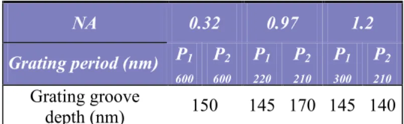
The same simulations have been performed for the gratings enabling 0.97 and 1.2 NAs. From those simulations we have determined the grating groove depth considering fabrication processes and diffraction efficiencies. For fabrication process purpose, the phase gratings were chosen with an equal line-to-space ratio for both P1 and P2 gratings. In table 3, the chosen groove depth for each grating are summarized. They were chosen to have sufficient grating efficiencies in TE mode while not scaling down too much the depth so as not to put too much constraints on the fabrication technology.
Simulations have been done for both TE and TM modes because this setup will be used for the study of polarization effects at oblique angles. Because it becomes really challenging to fabricate gratings with diffraction efficiency optimized in TM mode, groove depths have been chosen to have sufficient efficiency in TE mode.
V. EXPERIMENTAL RESULTS
The first grating pairs enabling NA of 0.32 and 0.97 was used for the first trials to demonstrate immersion interference imaging with the double diffraction grating immersion interferometer. A GAM excimer laser at 193nm with a spatial coherence of 500 µm and a temporal coherence of 900 µm was used enabling a DOF up to 352 µm (table 2). Before reaching the first diffraction grating the beam was spatially filtered to improve the field uniformity. A polarizer was used in all experiments unless specified to polarize the light in TE mode (s-polarization) in order to assure high contrast fringes. Fig. 4 shows the interferometric setup and its environment. A Fizeau interferometer is placed above the gratings to adjust the gratings parallelism. The deionized water dispensed between the last grating and the wafer is filtered and temperature controlled.
After compacting the setup to suppress the effect of vibrations on line profiles, high contrast lines have been obtained in immersion. XP1020B photoresist was used for all experiments with thickness of 190 nm and 70 nm for respectively the 150-nm and the 50-nm half-pitch lines. AR40 was used as a bottom anti-reflective coating with a thickness of 80 nm and
XP1029 was used as a topcoat with a thickness of 38 nm to suppress the effects of contamination. All materials were supplied by Rohm&Haas. Figure 5 shows results obtained with the immersion achromatic interferometer. High-contrasted lines are obtained with nice straight profiles even at small dimensions. Resolution from 150 to 50 nm has been demonstrated in both dry and wet lithography.
VI. SUMMARY
We have completely designed an immersion interferometer to generate resist patterns with period down to 60 nm. The great advantages of this setup compared to others already existing is that it is possible to use a basic commercial ArF excimer laser as the exposure source and that the main optical elements are home-fabricated enabling us to switch to various applications such as high index fluids testing and contact holes printing in a very simple way. Calculations have been performed to evaluate the depth of focus of the system and to determine the gratings groove depths that enable sufficient diffraction efficiency. However the depth of focus is affected by the small coherence length of the laser, even though it remains much higher than in industrial projection tools since the lowest DOF achievable in the immersion configuration is of 74 µm for 80 nm pitch gratings. Imaging at 0.32 and 0.97 NA in both dry and immersion was demonstrated and polarization effects at oblique incidence angles have been shown.
VII. APPENDIX
Diffraction angles in function of the refractive index, the grating period, the incidence angle and the wavelength:
) sin ( 1 sin 1 1 θ λ γ = − P n (1) ( sin ) 1 sin 1 1 θ λ β = + P n (2) θ λ γ sin sin 1 − = P g (3) θ λ β sin sin 1 + = P g (4) ) sin ( 1 sinγ2 = λ − θ Q n (5) ( sin ) 1 sinβ2 = λ + θ Q n (6) ) sin ( 1 sinγ = λ − θ Q N e (7) ( sin ) 1 sinβ = λ + θ Q N e (8)
(
)
(
)
(
)
(
λ)
λ π δ λ θ λθ δ π θ λ δ π λ λ λθ δ π θ λ δ π λ λ λθ δ π θ λ δ π λ λ λθ δ π ∆Φ d . Q N 2 ) de e .( 2 d . Q N 2 ) de e .( 2 d . Q n 2 ) d d .( 2 d . Q n 2 ) d d .( 2 d . P 2 ) dg g .( 2 d . P 2 ) g g .( 2 d . P n 2 ) d d .( 2 d . P n 2 ) d d .( 2 d 2 2 2 2 3 2 2 2 2 2 2 2 2 2 3 2 2 2 2 2 2 2 1 2 3 2 2 1 2 2 1 2 1 1 2 3 2 2 1 2 1 1 − ± + − ± + − ± + − ± + − ± − − ± − − ± − − ± − = (9)REFERENCES
[1] B. W. Smith, A. Bourov, Y. Fan, L. V. Zavyalova, N. V. Lafferty, F. C. Cropanese, Proc. SPIE Vol. 5377, 273 (2004).
[2] A. Yen, “Fabrication of large-area 100-nm-period gratings using achromatic holographic lithography”, Ph.D. dissertation (Massachusetts Institute of technology, Cambridge, Mass., 1991).
[3] J. A. Hoffnagle, W. D. Hinsberg, M. Sanchez, F. A. Houle, J. Vac. Sci. Technol. B 17, 3306 (1999).
[4] Alex K. Raub, S. R. J. Brueck, Proc. SPIE 5040, 667 (2003).
[5] A.Bourov, Y. Fan, F. Cropanese, N. Lafferty, L. Zavyalova, H. Kang, B.W. Smith, Proc. SPIE 5377, (2004).
[6] E. H. Anderson, K. Komatsu, H. I. Smith, J. Vac. Sci. Technol. B 6 (1), 216 (1987). [7] T.A. Savas, Satyen N. Shah, M. L. Schattenburg, J. M. Carter, and Henry I. Smith, J. Vac. Sci. Technol. B 13 (6) 2732 (1995).
[8] T. A. Savas, M. L. Schattenburg, J. M. Carter, and Henry I. Smith, J. Vac. Sci. Technol. B 14 (6), 4167 (1996).
[9] M. Switkes, R. R. Kunz, R. F. Sinta, M. Rotschild, P. M. Gallagher-Wetmore, V. J. Krukonis, K. Williams, Proc. SPIE 5040, 690 (2003).
[10] A. Yen, E. H. Anderson, R. A. Ghanbari, M. L. Schattenburg, and H. I. Smith, Appl. Opt. 22, 4540 (1992).
[11] M. G. Moharam and E. B. Grann and D. A. Pommet and T. K. Gaylord, J. Opt. Soc. Am. 12, 1068 (1995).
FIGURE CAPTION
Fig.1. Schematic of the immersion achromatic interferometric configuration and diagram for calculating the optical paths of two arms of the double diffraction gratings interferometer. Fig.2. Numerical apertures function of the gratings period P1 and P2 of the double diffraction grating interferometer.
Fig.3. Diffraction efficiencies in percent of fused silica gratings at 193 nm as a function of groove depth and fractional linewidth. a) First-order diffraction efficiency for TE polarization at normal incidence on a 600-nm-period grating. b) Second-order diffraction efficiency for TE polarization at 18.8° incidence on a 600-nm-period grating. c) First-order diffraction efficiency for TM polarization at normal incidence on a 600-nm-period grating. d) Second-order diffraction efficiency for TM polarization at 18.8° incidence on a 600-nm-period grating.
Fig. 4. Picture showing the experimental setup of the double diffraction grating immersion interferometer.
Fig. 5. Resist images using water immersion lithography. a) 150 nm half-pitch corresponding to 0.32 NA. b) 50 nm half-pitch corresponding to 0.97 NA.
TABLE CAPTION
Table 1. Gratings designs created for the immersion double diffraction interferometer.
Table 2. Depth of focus values for different NA configurations of the double diffraction grating interferometer.
Fig. 3 :
a) b)
Fig. 5 :
Table 1:
NA 0.32 0.97 1.2
P1 (nm) 600 220 300 P2 (nm) 600 210 210
Table 2: NA 0.32 0.97 (dry) 0.97 (immersion) 1.2 DOF (µm) 352 30 126 74
Table 3: NA 0.32 0.97 1.2 Grating period (nm) P1 600 P2 600 P1 220 P2 210 P1 300 P2 210 Grating groove depth (nm) 150 145 170 145 140