1 INTRODUCTION
Nowadays, production of renewable energies is a ma-jor issue. Amongst them, offshore wind energy is ex-panding fast, due to high velocity and constant winds that can be found. In the near future, many wind farms will built and those wind farms will be located closer and closer to traffic lanes. In addition, the use of Off-shore Supply Vessels within the farms is required to perform a regular maintenance. Therefore, the proba-bility of a collision occurring between a ship and on offshore structure cannot be neglected. The conse-quences of such an impact could be also severe, as it could lead to loss of human lives or to ecological or economic damage. This explains why it is required to perform a collision risk analysis for every new off-shore project.
Some design offices currently use finite elements simulations to assess the resistance of offshore struc-tures submitted to ship impacts, which provides accu-rate results but is time-demanding. To overcome this issue, several authors developed semi-analytical methods based on the decomposition of the structure into large structural elements, as done by Soreide et al. (1993) for offshore tubular structures. In this method, both local deformations at impact point and global bending of the jacket are considered. Follow-ing this approach, the authors of the present work veloped a solver based analytical formulation, de-rived from plastic limit analysis, to compute the resistance of an offshore jacket impacted by a ship and the energy dissipated during the collision.
In the present paper, the analytical solver is briefly presented and the methodology followed to validate the theoretical developments is described. Then, “an-alytical” and finite element solvers are used to simu-late many ship-jacket collision scenarios. The hypoth-eses considered for these calculations are presented and resulting resistant forces and deformation ener-gies are compared.
1.1 Analytical method
Before deriving analytical expressions to assess the resistant force of the jacket, many numerical simula-tions were carried out in order to better understand its global behavior and to identify the involved defor-mation modes: global motion of the whole structure, crushing of the impacted cylinder, punching of legs by compressed braces and deformation at the base of the jacket.
The use of plastic limit analysis requires to assume a displacement field for each deformation mode. The corresponding dissipated energy rate is then derived and the analytical expression of the resistant force is deducted by application of the upper bound theorem as described by (Jones, 1997). This method was suc-cessfully applied by (Buldgen et al. 2014) to derive the crushing resistance of an oblique cylinder im-pacted by a bow or a bulb, by (Hsieh, 2015) to inves-tigate the energy dissipated by plastic deformation of the legs which are punched by a compressed brace and by (Pire et al. in prep.) to study the multiple de-formation modes occurring at the base of the jacket.
Analytical formulations were recently combined into a global algorithm (Le Sourne et al. 2016), in
Validation of a simplified method for the crashworthiness of offshore
wind turbine jackets using finite elements simulations
T. Pire & S. Echeverry & P. Rigo
University of Liège, Liège, Belgium
L. Buldgen
HELMo Gramme, Liège, Belgium
H. Le Sourne
ICAM, Nantes, France
ABSTRACT: The work presented in this paper focuses on crashworthiness of jacket foundations used to sup-port offshore wind turbines in moderately deep waters. In a previous research work, the authors have developed a solver based on analytical formulations, derived from limit plastic analysis, to assess the damage of such foundations when impacted by a ship. The present paper describes the methodology followed to perform nu-merical validations of the theoretical developments, including a description of the finite element models, the computation hypotheses and the simulations performed using LS-DYNA code. Many parameters describing the collision scenario are investigated, namely the type, the mass, the initial velocity and the trajectory of the strik-ing ship. Some comparisons between analytical and numerical results are finally shown.
which all the deformation modes are independently triggered by comparing the resistant forces. The total resistance and internal energy of the jacket as well as striking ship penetration can finally be post-pro-cessed.
1.2 Numerical method
Many authors performed numerical simulations of a ship colliding an offshore wind turbine jacket to high-light the effect of several parameters.
Most researches considered Offshore Supply Ves-sels as colliding ship, with a mass comprised between 2500 and 5250 tons (added mass included) and an in-itial velocity range of 2 to 6 m/s.
It was found out by Vredeveldt et al. (2013) and Le Sourne et al. (2015) that the dynamics of the wind turbine tower with the nacelle can be ignored when computing the structure resistance for the considered initial velocity range. Le Sourne et al. (2015) also demonstrated that the effect of gravity can be ne-glected.
The effect of relative stiffness of the striking ship and the collided structure was also investigated by au-thors, such as Travanca & Hao (2014a, b) or Le Sourne et al. (2015). The structural behavior is dras-tically different according to the type of ship, as an OSV is much more flexible than a bulk carrier, for instance.
Soil structure interaction effect was studied by Le Sourne et al. (2015). The boundaries of the jacket into the seabed were considered either perfectly clamped or flexible and then modelled using spring elements associated with in-situ measurements values. The comparison of resulting crushing forces showed that a perfectly clamped model provides results with very negligible differences with a more realistic model.
All the previously cited authors neglected the ef-fect of wind, waves, current, hydrostatic damping… as the corresponding forces are small with regard to the collision forces.
Finally, Amdahl & Holmas (2011) studied high energy impacts, larger than 500 MJ. It was demon-strated that the collided structure would collapse in any case. As wind turbine should preferably not fall on the ship, it was shown that the water depth and the jacket layout are the determinant parameters.
Similar simulations were performed for ship colli-sions on offshore wind turbine monopiles, amongst others Bela et al. (2015). It was shown that many pa-rameters that can be neglected for jackets are deter-minant in case of ship collisions on monopiles. For example, the dynamics of the tower, including the mass of the nacelle, gravity…, plays a large role in the deformation of the structure. The initial kinetic energy of the colliding ship and the orientation of wind are also important parameters on the collapse process. Finally, the soil-structure interaction
influ-ences also the deformation at the bottom of the mono-pile, and therefore on the motion of the whole struc-ture.
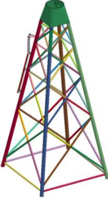
Figure 1. Jacket finite element model
Some standards related to ship-offshore structures collisions were implemented. We can mention the NORSOK N-004 Standard (2004) based on the works of Amdahl & Johansen (2001) or the recommended practice "Design for accidental loads" by DNV (2010).
2 COLLISION ANALYSIS
2.1 Finite elements model
All finite elements models are built with PATRAN-NASTRAN (MSC) and the finite elements simula-tions are carried out using LS-DYNA (LSTC) explicit solver.
The particulars of the jacket are given in Table 1, while a view of the finite elements model is proposed in Fig. 1.
Table 1. Jacket particulars
Height (m) 56 Legs ext. diam. (m) 1.3 Bottom width (m) 25 Legs thick. (m) 0.05 Top width (m) 6.4 Braces ext. diam. (m) 0.65 Braces thick. (m) 0.05
On top of a real jacket is a platform and the transi-tion piece used to connect the structure with the tower. This piece can be considered as rigid, and it is modelled with a rigid plate on top of the jacket finite elements model to connect the four legs.
Assuming that the soil is rigid, clamped boundary conditions are imposed to the legs feet at seabed level. The tower is not explicitly modelled but rather repre-sented by a lumped mass. Gravity loads are not con-sidered as it was demonstrated that their influence on
the final result is negligible. Rupture is not considered in a first step of the research, but will be investigated later on.
Figure 2. Jacket material behaviour law
Figure 3. Non-bulbous bow finite elements model
Figure 4. Bulbous bow finite elements model
The jacket is modelled with Reduced Integrated Belytchko-Tasy shell elements (Hallquist 2013). The material is considered as elastic – perfectly plastic with a flow stress σ0 of 255 MPa, as shown in Fig. 2.
As shown among others by (Le Sourne, 2015), the type of colliding ship has a major influence on the repartition of dissipated energy between the ship and the structure. In both analytical and numerical simu-lations, we consider only rigid striking ships, which leads of course to conservative results regarding the offshore structure. Those will be a non-bulbous and a bulbous Offshore Supply Vessels, each with a typical mass of 6000 tons (added mass included). Their finite elements model are depicted respectively in Fig. 3 and Fig. 4.
The contact between the ship hull and the jacket is modelled using the AUTOMATIC-SURFACE-TO-SURFACE card of LS-DYNA.
A surge initial velocity is imposed to the striking ship and its vertical and transversal displacements as well as all rotations are restrained, which means that the ship direction remains constant during the whole crushing process.
For all the simulations, an initial ship velocity of 5 m/s is chosen in order to produce representative final damage on the jacket. The OSV impacts thus the jacket with an initial kinetic energy of 75 MJ that has to be dissipated by the offshore structure.
Figure 5. Collision scenario between two connections
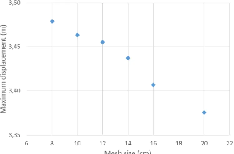
Figure 6. Maximum displacement for each mesh size
2.2 Size of elements
A mesh sensitivity analysis is performed in order to optimize the jacket mesh shell element size. The col-lision scenario depicted in Fig. 5 is simulated using mesh sizes within a range of 8 to 20 cm. A fine mesh provides more accurate results but is of course more time-demanding.
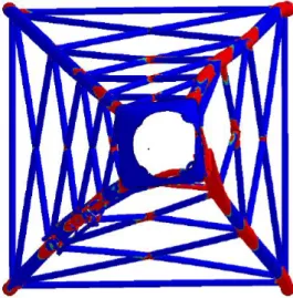
Figure 7. Collision scenario on a connection
Figure 8. Angle of collision
The jacket mesh particulars and resulting compu-ting time for all considered element sizes are given in Table 2.
Table 2. Jacket mesh properties and computation time Element
size (cm)
Nb. of elts Nb. of nodes Computing time
20 66,683 65,888 1h13' 16 105,497 104,646 2h33' 14 132,212 131,249 4h31' 12 179,535 178,462 6h16' 10 263,464 262,215 11h23' 8 395,358 394,005 16h36'
The computation time increases very fast with the refinement of the mesh, because of both the Courant-Friedrich-Levy condition and the use of the contact card. Indeed, contact is considered to occur when the distance between a node of the colliding ship and a shell element of the jacket becomes zero. At each it-eration the distance between the nodes of the ship and the selected shell elements of the jacket is computed. With an increasing number of nodes, the number of distances that have to be computed increases also.
For each mesh size, the maximum displacement of the ship, plotted in Fig. 6, allows to conclude that the convergence tends to a value of 3.47 m. It also ap-pears that the impact force does not change signifi-cantly when element size becomes lower than 10 cm. The next simulations are thus performed using this mesh size, which is according to the authors the best compromise between accuracy and time.
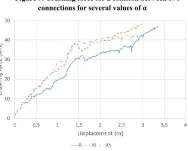
Figure 9. Crushing force for a collision between two connections for several values of α
Figure 10. Crushing force for a collision on a connec-tion for several values of α
Figure 11. Crushing force for α = 0 depending on the collision point
2.3 Non-bulbous bow simulations
In order to validate the analytical solver, many nu-merical simulations were performed for different ship-jacket collision scenarios. In all cases, the ship strikes one jacket leg, either between two connections of braces (see Fig. 5) or directly on a connection (see Fig. 7). Collisions against braces are not considered here as it was demonstrated by Le Sourne (2015) that leg impacts are more harmful than brace impacts.
The validation process aims to verify that the ana-lytical solver is able to provide accurate results for any collision scenario possible. Impact locations and striking ship trajectories are chosen to simulate the most representative collision scenarios and therefore to guarantee the validity of the model for any colli-sions.
The selected collision angles α are 0°, 30° and 45° (see Fig. 8).
The contact forces resulting from an impact lo-cated between two connections and on a connection are given respectively in Fig. 9 and Fig. 10 for the different values of α. In addition, the influence of the impact location on the jacket resistant force is high-lighted in Fig. 11, where the collision angle α = 0 in both cases.
It can be concluded from Fig. 9 and Fig. 10 that the jacket resist more for a larger value of the collision angle α. Indeed, for α = 0, mainly one plane of the jacket withstands the impact load, while for other val-ues of α, a second plane is activated, which gives more rigidity. From Fig. 11, it appears also clearly that the local stiffness on a connection is larger than the one between two connections.
2.4 Bulbous bow simulations
The same simulations are performed with the bulbous bow presented in Fig. 4. As for the non-bulbous bow, the jacket resistance increases with the collision angle α for a given ship and a given impact location.
However, when a bulbous bows strikes the jacket, the number of collisions configurations is much larger than for non-bulbous one. Indeed, depending on the geometry of both the ship and the jacket, impacts may occur at different places. Both the stem and the bulb may impact either between two connections or on a connection. The jacket structural behavior depends of course greatly on these conditions.
2.5 Effect of rupture
Up to now, simulations were performed without con-sidering rupture. To determine if it is necessary to take this phenomenon into account when developing an the analytical solver, the elastoplastic law used to model the jacket material behavior is associated to an erosive shear strain criteria.
Corresponding failure strain threshold value is de-termined according to Lehmann & Peschmann (2002).
𝜀𝑓 = 𝜀𝑔+ 𝜀𝑒 𝑡
𝑙𝑒 (1)
where εf is the failure strain, εg is the uniform
strain, εe is the necking strain and t/le is the
thick-ness/element size ratio.
Previous formula is valid as far as the structure de-forms mainly in membrane tension. The elastoplastic erosive law is thus only applied to areas which are submitted to tension, such as the impacted leg or areas located between connections with braces (see Fig. 5).
As the deformation of impacted cylinders involves mainly local bending and shearing, rupture is inten-tionally not considered in those areas. Similarly, parts where braces connect to legs are also excluded due to the occurrence of complex internal efforts distribu-tion. Rupture of stretched braces is also disregarded as their elongation remain small. As the rear legs are concerned, they are submitted mainly to compression forces and are thus supposed to deform without fail-ure.
Collision scenarios described previously are simu-lated again but a failure strain criteria calcusimu-lated by Eq. (1) is now considered in areas where tension fail-ure may occur. Considering 75 MJ of impact energy, it appears that failure never occurs on the jacket, whatever is the collision scenario.
However, it is obvious that some components of the jacket may actually fail in reality, more particu-larly the impacted cylinders or the legs which are se-verely punched by braces. Nevertheless, the lack of suitable failure criterion available in the commercial-ized version of LS-DYNA prevented us from model-ing such damage properly.
Figure 13. Impacted cylinder local crushing mode
Figure 14. Punching mode
Figure 15. Base deformation mode
3 ANALYTICAL MODEL
Several steps were followed to develop the analytical solver. First, the main deformation modes were inves-tigated from some numerical simulations. For each identified deformation mode, a kinematic admissible displacement field was postulated and deformation energy rate 𝐸̇𝑖𝑛𝑡 was analytically derived from plastic limit analysis. The corresponding resistant force 𝑃 was then obtained from the upper-bound theorem:
𝑃 = 𝐸̇𝑖𝑛𝑡/𝛿̇ (2) where 𝛿̇ is the ship surge velocity.
All the deformation modes were finally combined into the global algorithm depicted in Fig. 16 in order to compute the time evolution of the jacket total re-sistance (Le Sourne et al. 2016).
3.1 Deformation modes
The numerical simulations highlighted four main de-formation modes, namely
Overall motion of the structure (Fig. 12)
Local crushing of the impacted cylinders (Fig 13)
Punching of legs by compressed braces (Fig. 14)
Deformation at the base of the jacket (Fig. 15) The resistance of the jacket in the overall motion mode is computed following an approach similar to nonlinear finite elements method. Each cylinder is considered as one single element and its stiffness is computed as for a beam element with semi-rigid con-nections (varying between perfect hinge and perfect clamping), taking into account possible plastic hinges at the extremities and at the middle of the elements. The global stiffness matrix is then built by assembling elementary matrices, as done in finite element ap-proach. The plastic surface is defined following Eu-rocode rules (2005).
The crushing of the impacted cylinder was studied by Buldgen et al. (2014) from results obtained by Hoo Fatt et al. (1991), Wierzbicki et al. (1988) and Ze-inoddini et al. (1998). The impacted cylinder is con-sidered as rings that can slide without shearing along generators. Those rings dissipate energy both by rota-tion of moving plastic hinges and by change of cur-vature of the sections located between the hinges. Re-garding the generators, the dissipation is due to their elongations.
Figure 16. General algorithm
Buldgen’s work was then extended by Hsieh (2015) who derived similarly the internal energy rate and the resistant force of legs which are punched by compressed braces. The deformation pattern at the base of the jacket was studied by Pire et al. (2017).
3.2 General algorithm
The general algorithm presented in Fig. 16 combines all analytical developments and allows to compute the total resistance of the jacket.
At each time step, the resistant force in all de de-formation modes are computed, considering the effect of one deformation mode on each other. For example, the reduction of section of a leg due to punching re-duces the stiffness of the cylinder in the overall mo-tion mode.
All these resistance forces are then compared and only the deformation mode with the minimum re-sistant force is considered. From the total rere-sistant force, the acceleration of the ship can be updated.
This procedure is followed until the velocity of the striking ship becomes zero.
Figure 17. Crushing force comparison for case A0
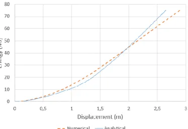
Figure 18. Dissipated energy comparison for case A0
4 COMPARISON OF BOTH MODELS
Resistant forces and deformation energies obtained analytically are compared in Figs 17 to 20 with the one obtained from numerical simulations, keeping of course the collision scenarios identical (impact point, trajectory…). For all of them, a 6000 tons rigid ship
(added mass included) impacts the jacket at an initial velocity of 5 m/s, which corresponds to an initial ki-netic energy of 75 MJ.
Only some results for non-bulbous ship collision are presented in this paper. In Figs 17 to 20 and in table 3 below, collisions between two connections are denoted A (Fig. 5) while collisions on a connection are denoted B (Fig. 7). The following number denotes the collision angle α (Fig. 8).
As shown by previous figures and by Tab. 3 below where the striking ship penetrations have been com-pared for different collision scenarios, the results ob-tained from the analytical solver are rather in good accordance with the numerical ones, the discrepancy not exceeding 9%. It appears also that the analytical approach is conservative in the majority of the cases.
Figure 19. Crushing force comparison for case B45
Figure 20. Dissipated energy comparison for case B45
Table 3. Maximum displacements and error Simul. Max. ship
disp. (anal) Max. ship disp. (num) Disc (%) A0 3m78 3m59 5 A30 3m55 3m32 7 A45 3m53 3m33 6 B0 3m52 3m36 5 B30 2m72 2m98 9 B45 2m65 2m90 9
5 CONCLUSION
In this paper, the authors described the process used to validate an analytical solver based on plastic limit analysis able to assess the crashworthiness of an off-shore wind turbine jacket when it is impacted by a ship bow. Numerous numerical simulations were per-formed for different collision scenarios and the en-ergy dissipated by the jacket as well as its resistant force were compared to the ones obtained with the an-alytical solver.
First, the numerical simulations were described. As was demonstrated in some previous papers, the in-fluence of the tower and the gravity effects can be dis-regarded. The jacket legs are considered as clamped as the soil-stiffness interaction can be also neglected. 6000 tons non-bulbous and bulbous colliding Off-shore Supply Vessels were both considered in the simulations. They are supposed to strike the jacket at an initial velocity of 5 m/s, which corresponds to a kinetic energy of 75 MJ. In this paper, the striking ship is considered as rigid, which leads to conserva-tive results with regard to the jacket as the whole en-ergy is dissipated by deformation of the jacket.
The simulations performed involved impacts on a leg, either between two connections with braces or on one of these connections, and different angles of col-lision. The results showed that the resistance of the jacket increases when the impact occurs on a brace-leg connection or when the angle between the ship di-rection and the main planes of the jacket increases.
In order to simulate possible failure, an elasto-plastic behavior law including a shear stress failure criteria was considered for the parts mainly submitted to tensile internal forces. For the considered impact energy, numerical simulations show that rupture does not occur in any part of the jacket. However, such results are questionable because the stress state of some severely deformed parts is bi-axial or tri-axial and involves bending and shearing deformation modes, which are not correctly modelled by the clas-sical erosive law available in the commercialized ver-sion of LS-DYNA.
Anyway, by comparing the energy dissipated plas-tically by the jacket as well as its resistant force both calculated by the developed analytical solver and by LS-DYNA, it can be concluded that the analytical solver can be used with confidence for rigid ship-de-formable jacket collision simulations.
Further developments will aim to include in the an-alytical model the deformability of the striking ship. Indeed, as was shown by Le Sourne (2015), depend-ing on the type of colliddepend-ing ship, a significant part of energy may be dissipated by deformation of the strik-ing ship (up to 80% in case of an OSV bow collision but only 20% in case of an ice-class bulk carrier side impact).
6 AKNOWLEDGEMENT
The authors would like to thank the FRIA and Region “Pays de la Loire” for their financial support, STX and Bureau Veritas for their participation in defining the scope of the work and MSC (NASTRAN) and LSTC (LS-DYNA) for their technical support.
7 REFERENCES
Amdahl J. and Holmas T. 2011. High energy ship collisions with jacket supported offshore wind turbines. Proceedings of the in-ternational conference on computational methods in marine en-gineering, Barcelona, Spain.
Bela A., Le Sourne H., Buldgen L. and Rigo P. 2015. Numerical crashworthiness of an offshore wind turbine monopile impacted by a ship. Proceedings of the MARSTRUCT 2015 5th Interna-tional Conference on Marine Structure. Taylor & Francis Group.
Buldgen L., Le Sourne H. and Pire T. 2014. Extension of the super-elements method to the analysis of a jacket impacted by a ship. Marine Structures, 38.
European committee for standardization. 2005. Eurocode 3: Design of steel structures EN1993.
Hallquist J.O. 2006. LS-DYNA theoretical manual, Livermore Software Technology Corporation.
Hoo Fatt MS and Wierzbicki T. 1991. Damage of plastic cylinders under localized pressure loading. International Journal of Me-chanical Sciences, 33: 999-1016.
Hsieh J.R. 2015. Analytical formulations for ship-offshore wind tur-bine collisions. Master Thesis, Nantes: ICAM, in the framework of EMSHIP Erasmus Mundus Master Course in Integrated Ad-vanced Ship Design.
Jones N. 1997. Structural impact. Cambridge university press.
Lehmann E. and Peschmann J. 2002. Energy absorption by the steel structure of ships in the event of collisions. Marine Structures, 15(4-5): 429-441.
Le Sourne H., Barrera, A. and Maliakel J. B. 2015. Numerical crashworthiness analysis of an offshore wind turbine jacket im-pacted by a ship. Journal of Marine Science and Technology, 23(5).
Le Sourne H., Pire T., Hsieh J. R. and Rigo P. 2016. New analytical developments to study local and global deformations of an off-shore wind turbine jacket impacted by a ship. Proceedings of International Conference on Collision and Grounding of Ships, Ulsan, Korea.
Pire T., Le Sourne H., Echeverry S., Rigo P. 2017. Analytical for-mulations to assess the energy dissipated at the base of an off-shore wind turbine jacket impacted by a ship. To be submitted to Marine Structures.
Soreide T., Amdahl J., Eberg E., Homas T. and Hellan. 1993. O. USFOS: A computer program for progressive collapse analysis of steel offshore structures. SINTEF.
Travanca J., Hao H. 2014. Numerical analysis of steel tubular mem-ber response to ship bow impacts. International Journal of Im-pact Engineering, 64: 101-121.
Travanca J. Hao H. 2014. Dynamics of steel offshore platforms un-der ship impact. Applied Ocean Research, 47: 352-372. Vredeveldt A. W., Schipperen J. H. A., Nassar Q. H. A., Spaans C.
A. 2013. Safe jacket configurations to resist boat impact. Leira J, editor. Collision and grounding of ships and offshore struc-tures.
Wierzbicki T., Suh M. S. 1988. Indentation of tubes under com-bined loading. International Journal Mechanical Sciences, 30(3/4): 229-248.
Zeinoddini M., Harding J.E., Parke G.A.R. 1998. Effect of impact damage on the capacity of tubular steel members of offshore structures. Marine Structures, 11: 141-157.