UNIVERSITY DE
SHERBROOKE
Faculte de genie Departement de genie civil
PUNCHING SHEAR BEHAVIOUR OF CONCRETE TWO-
WAY SLABS REINFORCED WITH GLASS FIBER-
REINFORCED POLYMER (GFRP) BARS
COMPORTEMENT AU POINQONNEMENT DE DALLES
BIDIRECTIONNELLES EN BETON ARME DE BARRES
D ’ARMATURE EN POLYMERE RENFORCES DE FIBRES
Jury:
Brahim Benmokrane (directeur de recherche) Edward Sherwood (Examinateur)
Marie-Josee Nollet (Examinateur) Charles-Philippe Lamarche (Rapporteur)
These de doctorat es sciences appliquees Speciality: genie civil
Mohamed Ashour Wardany HASSAN
1+1
Library and Archives Canada Published Heritage Branch Bibliotheque et Archives Canada Direction du Patrimoine de I'edition 395 Wellington Street Ottawa ON K 1A0N 4 Canada 395, rue Wellington Ottawa ON K1A 0N4 CanadaYour file Votre reference ISBN: 978-0-494-96322-7 Our file Notre reference ISBN: 978-0-494-96322-7
NOTICE:
The author has granted a non
exclusive license allowing Library and Archives Canada to reproduce, publish, archive, preserve, conserve, communicate to the public by
telecomm unication or on the Internet, loan, distrbute and sell theses
worldwide, for commercial or non commercial purposes, in microform, paper, electronic and/or any other formats.
AVIS:
L'auteur a accorde une licence non exclusive permettant a la Bibliotheque et Archives Canada de reproduire, publier, archiver, sauvegarder, conserver, transmettre au public par telecomm unication ou par I'lnternet, preter, distribuer et vendre des theses partout dans le monde, a des fins com merciales ou autres, sur support microforme, papier, electronique et/ou autres formats.
The author retains copyright ownership and moral rights in this thesis. Neither the thesis nor substantial extracts from it may be printed or otherwise reproduced without the author's permission.
L'auteur conserve la propriete du droit d'auteur et des droits moraux qui protege cette these. Ni la these ni des extraits substantiels de celle-ci ne doivent etre imprimes ou autrement
reproduits sans son autorisation.
In compliance with the Canadian Privacy A ct some supporting forms may have been removed from this thesis.
W hile these forms may be included in the document page count, their removal does not represent any loss of content from the thesis.
Conform em ent a la loi canadienne sur la protection de la vie privee, quelques
form ulaires secondaires ont ete enleves de cette these.
Bien que ces form ulaires aient inclus dans la pagination, il n'y aura aucun contenu manquant.
PUBLICATION DISSERTATION OPTION
This dissertation consists o f the following four articles that have been accepted or submitted for publication in referred journals:
The first paper, presented in Chapter 4, has been accepted for publication in the ACI Structural Journal.
The second paper, presented in Chapter 5, has been accepted for publication in the Canadian Journal for Civil Engineering (CJCE).
The third paper, presented in Chapter 6, has been accepted to the ASCE Journal o f Composites for Construction.
Finally, the fourth paper, presented in Chapter 7, has been submitted to the ASCE Journal o f Composites for Construction.
Abstract
ABSTRACT
Deterioration o f reinforced-concrete (RC) structures due to corrosion o f steel limits the service-life and increases the rehabilitation costs. Concrete slabs in parking structures deteriorate faster than any other structural elements because o f direct exposure to high concentrations o f chlorides used for snow and ice removal during winter seasons. The use o f fiber-reinforced polymer (FRP) bars as an alternative to conventional steel has emerged as a realistic and cost-effective solution to overcome the corrosion problems, particularly for concrete structure exposed to harsh environmental conditions.
Design o f RC flat slabs is often compromised by their ability to resist shear stresses at the punching-shear surface area. The connections between slabs and supporting columns could be susceptible to high shear stresses and might cause brittle and sudden punching-shear failure. These connections may become the starting points leading to catastrophic punching-shear failure o f a flat slab system when the steel reinforcement corrodes. Extensive research work has been conducted on the punching-shear behaviour o f steel-reinforced flat slabs. The punching-shear strength o f RC flat slabs reinforced with glass fiber-reinforced polymer (GFRP) bars, however, is yet to be fully investigated and understood. This is due to the limited research work on the subject and to the numerous parameters affecting punching-shear behaviour. In addition, the current FRP design codes and guidelines do not provide rational design models addressing the contribution o f the FRP as shear reinforcement (stirrups) for FRP-RC flat slabs.
Thus, this study aims at investigating the punching-shear behaviour o f concrete two-way slabs reinforced in flexure with GFRP bars. The investigation included two-way test specimens without shear reinforcement and others with carbon or glass FRP stirrups to evaluate the performance o f specimens without shear reinforcement and the effect o f shear reinforcement on the punching-capacity and performance. To achieve this, experimental and analytical studies were conducted. The experimental program included twenty-six interior slab-column connections reinforced with GFRP bars and two specimens reinforced with steel
Abstract
bars for comparisons. The specimens were tested through two phases. Phase I, focused on the two-way slabs without shear reinforcement and the investigated parameters were: (i) flexural reinforcement ratio (ranged from 0.34% to 1.66%) and type (steel and GFRP); (ii) GFRP compression reinforcement; (iii) slab thickness (200 mm and 350 mm); (v) column dimensions (300 x 300 mm and 450 x 450 mm); (iv) concrete strength (normal and high-strength concretes). Phase II, focused on the use o f FRP shear reinforcement (stirrups) and its effectiveness and contribution to the punching-shear capacity. The test variables considered in Phase II were: (i) the material o f stirrups (carbon and glass FRP); (ii) shear reinforcement ratio; (iii) stirrup spacing; (iv) the effect o f flexural reinforcement ratio on the effectiveness o f the shear reinforcement. The effect o f the different parameters considered in the two phases o f the experimental work were presented and discussed in four journal papers. Moreover, the test results and the findings contributed to the first field implementation o f GFRP bars in two flat slabs parking garages in Quebec's city, which were Quebec's city hall (Quebec, Canada, 2010) and La Chanceliere parking garage (the world's first flat-slab parking garage totally reinforced with GFRP bars) (Quebec, Canada, 2011).
On the other hand, the analytical study included assessing the accuracy o f the current punching-shear design provisions through comparing the test results o f the specimens tested herein and 35 specimens from literature. The provisions included CSA S806-12 (2012), ACI 440 (2006), BS 8110 (1997), and JSCE (1997).
Keywords'. Punching-shear, two-way, slab, flat slab, parking garage, fiber-reinforced polymer,
Resume
RESUME
La deterioration des structures en beton arme due a la corrosion de l’acier limite leur duree de vie et augmente les couts de reparation. Les dalles en beton dans les structures de stationnements etages se deteriorent plus vite que n ’importe quel autre element structural a cause de L exposition directe a de hautes concentrations de chlorures utilises comme sels de degla9age. L’utilisation de barres en polymere renforce de fibres (PRF) est une bonne alternative a L armature conventionnelle en acier particulierement pour les structures en beton exposees a des conditions environnementales severes.
Comportement au poin9onnement de dalles bidirectionnelles peut mener a une rupture fragile sans aucun avertissement. De nombreux travaux de recherche ont ete consacres a l’etude du comportement au poin9onnement de dalles en beton arme. Cependant la resistance au poin9onnement de dalles renforcees de barres en polymeres renforces de fibres de verre (PRFV) n ’a pas encore ete pleinement investiguee. Aussi, les codes et guides de design actuels des PRF ne foumissent pas d ’equations pour le calcul de la contribution des PRF comme armature de cisaillement (etriers).
Cette etude vise L investigation du comportement au poin9onnement de dalles bidirectionnelles renforcees en flexion avec des barres PRFV. L ’etude inclut des specimens d ’essais bidirectionnels sans et avec armature de cisaillement. Des etriers en carbone ou en verre ont fait l’objet de ces essais. Le programme experimental comprend vingt-six specimens de dalles renforcees de barres en PRFV et deux specimens renforces avec des barres en acier pour des fins de comparaison. Les echantillons ont ete testes en deux etapes. L’etape I a porte sur les dalles bidirectionnelles sans armature de cisaillement et les parametres investigues sont: (i) le pourcentage d ’armature en flexion (variant de 0,34% a 1,66%) et le type d ’armature (acier et PRFV); (ii) l’armature en compression en PRFV; armature d ’integrite; (iii) l’epaisseur de dalle (200 mm et 350 mm); (v) les dimensions des colonnes (300 x 300 mm et 450 x 4 5 0 mm); (iv) la resistance en compression du beton (betons normal et a haute resistance). L’etape II a porte, quant a elle, sur l’utilisation de renforcement de cisaillement en PRF (etriers) et sa contribution a la resistance au poin9onnement. Les variables d ’essais
Resume
considerees dans l’etape II sont: (i) le materiau des etriers (carbone ou verre); (ii) le pourcentage d ’armature de cisaillement; (iii) l’espacement des etriers; (iv) le pourcentage d ’armature en flexion. L ’effet des differents parametres consideres dans les deux etapes de l ’etude experimentale est presentee et analysee a travers quatre articles scientifiques. Les resultats d ’essais ont contribue a l’utilisation de barres en PRFV dans deux dalles de stationnements etages a Quebec : le stationnement de l’Hotel de Ville de Quebec en 2010 et le stationnement La Chanceliere (le premier stationnement au monde entierement renforce de barres en PRFV) en 2011.
Enfin, une etude analytique comprenant l’utilisation d ’equations de calcul de la resistance au poin9onnement a ete realisee dans le cadre de cette these. Cette etude a egalement compris l’analyse de 35 essais de dalles bidirectionnelles retrouves dans la litterature.
Keywords: Cisaillement, poin9onnement, dalle bidirectionnelle, polymere renforce de fibres, PRF, prediction, design, etrier, beton.
Acknowledsement
The candidate has participated in the following publications during his doctorate study at the University o f Sherbrooke:
A ccep ted /S u b m itted Journal Publications:
Dulude, C., H assan, M ., Ahmed, E. and Benmokrane, B., (2013), “Punching-Shear Behavior o f Flat Slabs Reinforced with Glass Fiber-Reinforced Polymer Bars", A C I Structural
Journal, 110(5): 723-734.
H assan, M., Ahmed, E. and Benmokrane, B., (2013), “Punching-Shear Behavior o f Flat Slabs Reinforced with Glass Fiber-Reinforced Polymer Bars”, Canadian Journal o f Civil
Engineering (CJCE), in press.
H assan, M., Ahmed, E. and Benmokrane, B., (2013), “Punching-Shear Strength o f Normal- and High-Strength Two-Way Concrete Slabs Reinforced with GFRP Bars”, ASC E
Journal o f Composites fo r Construction, in press.
H assan, M ., Ahmed, E. and Benmokrane, B., (2013), “Punching-Shear Behavior o f Two-Way Slabs Reinforced with FRP Shear Reinforcement.”, ASC E Journal o f Composites fo r
Construction, submitted.
Conference Publications:
H assan, M., Ahmed, E. and Benmokrane, B., (2013), “Preliminary Investigation on Punching-Shear Strength o f Flat Slabs with FRP Flexural and Shear Reinforcement.”, CSCE
2013, 3rd Specialty Conference on Material Engineering & Applied Mechanics, Montreal,
Quebec, May 29 to 1 June, 10 p.
H assan, M., Ahmed, E. and Benmokrane, B., (2012) “Punching shear strength prediction o f FRP-reinforced concrete flat slabs.”, 6th International Conference on Advanced Composite
Materials in Bridges and Structures, Kingston, Ontario, Canada, 22 - 25 May, 1 Op.
H assan, M., Dulude, C., Ahmed, E. and Benmokrane, B., (2011), “Punching Shear Strength o f Flat Slabs Reinforced with Glass Fiber-R.einforced Polymer (GFRP) Bars”, CSCE 2011,
General Conference, Ottawa, Ontario, June 14-17, 10 p. (CD-ROM).
Selected T ech n ical Reports:
H assan, M., Afifi, M., Ahmed, E. and Benmokrane, B., (2013), “Caracterisation d ’un nouvel etrier de cisaillement en materiaux composites pour les dalles de stationnements etages et les colonnes en beton : Essais structuraux en laboratoire sur des specimens grandeur nature.”. (Rapport d ’avancement II), for the Ministere du Developpement economique, Innovation et Exportation, 33 p.
H assan, M., Afifi, M., Ahmed, E. and Benmokrane, B., (2012), “Caracterisation d ’un nouvel etrier de cisaillement en materiaux composites pour les dalles de stationnements etages et les colonnes en beton : Essais structuraux en laboratoire sur des specimens grandeur nature.”.
Acknowledgement
(Rapport d ’avancement I), for the Ministere du Developpement economique, Innovation et Exportation, 22 p.
H assan, M ., Ahmed, E. and Benmokrane, B., (2011), “Punching-Shear Behavior o f Two-way Flat Slabs Concrete Reinforced with FRP Bars.” . (Rapport d’avancement), for the Ministere du Developpement economique, Innovation et Exportation, 17 p.
Dulude.C, H assan M., Ahmed E., Benmokrane B., (2010), “Conception et essais experimentaux sur des dalles de stationnements etages en beton arme d ’armature en materiaux composites de PRFV”, (projet de recherche MDEIE, N /R ef: 08-09-PSVT2-13462), (Technical report), Departement de genie civil, Universite de Sherbrooke, 74p.
H assan M ., Ahmed E., Benmokrane B., (2010), “Punching shear behavior o f reinforced concrete slabs reinforced with FRP bars.”, Definition o f doctorate research project (Technical report), Universite de Sherbrooke, Quebec.
Benmokrane B., Dulude C. et H assan M., (2010), “Evaluation de la performance structurale des etriers en polymeres renforces de fibres dans les dalles bidirectionnelles de stationnements etages”, (Technical report), Pultrall inc., mai, 14p.
Poster Presentations:
H assan, M ., Ahmed, E. and Benmokrane, B., (2011), “Punching shear behaviour o f two-way concrete flat slabs reinforced with FRP bars", Poster in CRIB conference, 21 June, Universite Laval, Quebec.
H assan, M ., Ahmed, E. and Benmokrane, B., (2010), “Punching shear behaviour o f two-way concrete flat slabs reinforced with and without FRP shear reinforcement", NSERC annual
Acknowledgement
ACKNOWLEDGEMENTS
I would like to express my sincere and deep gratitude to my supervisor, Prof. Brahim Benmokrane for his guidance, valuable advice, encouragement, and support throughout all stages o f the research project. Also, I would like to thank very much Dr. Ehab Ahmed, postdoctoral researcher, for his technical support and help.
Deep appreciation is due to the technical staff o f the Civil Engineering Department at the Universite de Sherbrooke, in particular Mr. Francois Ntacorigira, Martin Bernier, and Simon Kelley for their help in constructing and testing the specimens.
The financial support received from Quebec’s Ministry o f Economic Development, Innovation, and Export Trade, the Natural Sciences and Engineering Research Council o f Canada (NSERC) (Canada Research Chair Programme), Pultrall Inc. (Thetford Mines, Quebec), and the Fonds quebecois de la recherche sur la nature et les technologies (FQRNT) (volet equipe de recherche) is deeply appreciated.
Many thanks also go to all my colleagues and friends in the Department o f Civil Engineering at the Universite de Sherbrooke who in one way or another contributed and supported me throughout my study and my life style.
I would like to express my deep appreciation and thanks to m y parents, my sisters, and my w ife’s family, for their endless love, support, encouragement, duas, and prayers. The spiritual support o f all o f them cannot be praised enough. Finally, my words stand helpless, and cannot express my deep love and appreciation to my wife (Asmaa) for her continuous encouragement, and steadfast support throughout these years - without you I would never have gotten this far. I cannot present this work without expressing my love to my son (Omar) who enlightened my life with his smile; to them this thesis is dedicated.
Dedication
To m y m oth er a n iffa th e r
To th e m em ory o f m y fa th e r in la w "Jlhdefclaim ”
To m y fo vely w ife "Jtsmaa ” a n cfm y son "Omar”
Table o f Contents
TABLE OF CONTENTS
A B STR A C T... ii
RESU M E... iv
ACKNOW LEDGEM ENTS... viii
TABLE OF CONTENTS... x
LIST OF TABLES...xv
LIST OF FIG U RES...
xvi
LIST OF SYMBOLS...xx
CHAPTER 1
INTRODUCTION... 1
1.1 Background and Problem D efinition...1
1.2 Research Significance... 4
1.3 Objectives and O riginality...4
1.4 M ethodology...5
1.5 Organization o f the D issertation...6
CHAPTER 2
LITERATURE R E V IE W ... 9
2.1 G eneral... 9
2.2 FRP Composite M aterials... 9
2.3 General Characteristics o f FRP Reinforcing B a rs... 11
2.4 Shear Strength o f Concrete Two-Way S lab s... 14
2.4.1 Punching shear failure mechanism o f steel two-way slabs without shear reinforcem ent...16
Table o f Contents
2.4.2 Failure mode and shear strength o f steel two-way slabs with shear
reinforcement... 17
2.4.3 Punching shear o f FRP concrete two-way slabs reinforced with and without FRP shear reinforcement...19
2.5 Summary... 28
CHAPTER 3 EXPERIMENTAL PROGRAM...29
3.1 General... 29
3.2 Material Properties... 30
3.2.1 FRP and steel b a rs ... 30
3.2.2 FRP stirrups...32
3.2.2.1 Tension characteristic o f the straight portion... 32
3.2.2.2 Bend strength o f the FRP stirrups...33
3.2.3 Concrete... 40
3.3 Test Specimens’ Details...42
3.4 Fabrication o f Test Specimens...55
3.5 Instrumentations...58
3.6 Test Setup and Procedure... 64
CHAPTER 4 PUNCHING-SHEAR BEHAVIOUR OF FLAT SLABS
REINFORCED WITH GFRP BARS...67
4.1 Introduction... 69
4.2 Research Significance... 70
4.3 Experimental Program ... 71
4.3.1 Details o f test prototypes... 71
4.3.2 Material Properties... 73
4.3.3 Instrumentation and test setup...74
4.4 Test Results and Discussion... 75
4.4.1 Cracking and failure m o d e... 75
Table o f Contents
4.4.3 Load-deflection responses... 82
4.4.4 Strains...84
4.4.5 Crack w id th ... 85
4.5 Comparison o f Predictions and Experimental Results...87
4.6 Conclusions... 91
CHAPTERS PUNCHING
SHEAR
STRENGTH
OF
GFRP-
REINFORCED SLABS WITHOUT SHEAR REINFORCEM ENT...93
5.1 Introduction... 95
5.2 Experimental Program ... 96
5.2.1 Test Specimen D etails...96
5.2.2 Material Properties... 98
5.2.3 Instrumentation and test setup... 100
5.3 Test Results and Discussion... 101
5.3.1 Cracking and failure characteristics... 101
5.3.2 Load-deflection responses... 104
5.3.3 Punching-shear strength...105
5.3.4 Reinforcement strains... 110
5.4 Punching-Shear Capacity Equations... 112
5.4.1 CAN/CSA S806-12 (2 0 1 2 )...112
5.4.2 ACI-440.1R-06 (2 0 0 6 )...112
5.4.3 Japanese Design Recommendations (JSCE 1997)...113
5.4.4 Other Punching-Shear E quations... 113
5.4.5 Comparison between Experimental and Predicted Results...114
5.5... Conclusions... 116
CHAPTER 6
PUNCHING-SHEAR RESISTANCE OF NORMAL AND
HIGH-STRENGTH CONCRETE TWO-WAY SLA B S... 117
6.1...Introduction... 119
Table o f Contents
6.2.1 Materiel properties... 121
6.2.2 Test specim ens... 122
6.2.3 Instrumentations and test s e tu p ...123
6.3 Test Results and Discussion...125
6.3.1 Cracking and failu re... 125
6.3.2 Punching-shear capacity... 127
6.3.3 Load-deflection response...131
6.3.4 Reinforcement and concrete s tra in s... 133
6.3.5 Initial and Post-cracking Stiffness...136
6.4 Predications o f Punching-Shear Capacity... 137
6.4.1 CSA S806-12 (CSA S806, 2 0 1 2 )...137
6.4.2 ACI-440.1R-06 (ACI 440, 2 0 0 6 )...137
6.4.3 British Standards (BS 8110, 1997)... 138
6.4.4 Japanese Design Recommendations (JSCE, 1997)...138
6.4.5 Comparison between experimental and predicted resu lts... 138
6.5 Conclusions...142
CHAPTER 7
PUNCHING-SHEAR BEHAVIOUR OF GFRP TWO-WAY
SLABS USING FRP SHEAR REINFORCEM ENT...144
7.1 Introduction... 146
7.2 Experimental Program ... 147
7.2.1 Test specim ens... 147
7.2.2 Materiel p ro p erties...151
7.2.3 Test setup and instrumentation... 152
7.3 Test Results and D iscussions... 153
7.3.1 Cracks and failure envelop...153
7.3.2 Shear reinforcement effects on the failure m ode...155
7.3.3 Punching-shear capacity... 158
7.3.4 Load-deflection characteristics... 161
7.3.5 Flexural reinforcement and concrete stra in s... 162
Table o f Contents
7.4 Conclusions... 167
CHAPTER 8
SUMMARY AND CONCLUSIONS...170
8.1 Sum m ary... 170
8.2 Conclusions...171
8.2.1 Slabs without shear reinforcem ent... 171
8.2.2 Slabs with shear reinforcem ent...173
8.3 Conclusions en French... 174
8.3.1 Dalles sans armature de cisaillement... 174
8.3.2 Dalles avec armature de cisaillem ent...176
8.4 Recommendations for Future W ork... 177
REFERENCES... 179
List o f Tables
LIST OF TABLES
Table 2.1: Typical mechanical properties o f FRP reinforcement b ars... 14
Table 3.1: Properties o f the reinforcing b ars... 32
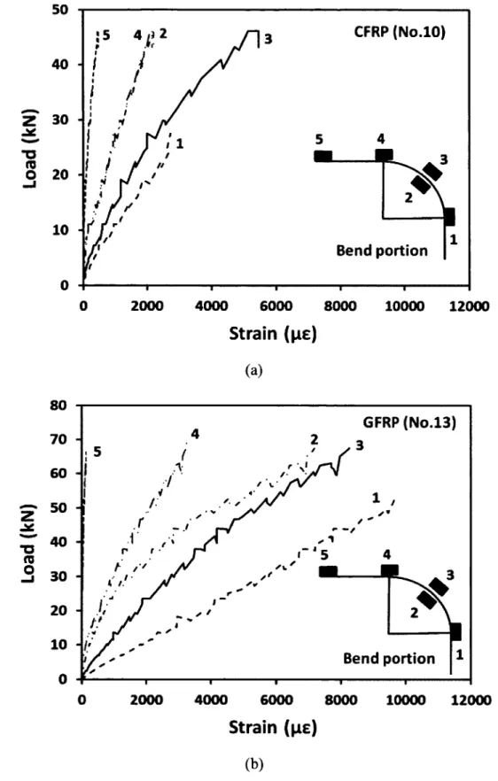
Table 3.2: Test results of the tension characteristics o f GFRP and CFRP N o .10 and No. 13 (9.5 mm and 12.7 m m )... 39
Table 3.3: Test results o f the bend strength o f FRP C-shaped stirrups...39
Table 3.4: Details o f test specim ens...54
Table 4.1: Details o f test prototypes...73
Table 4.2: Properties o f the GFRP reinforcing b a rs... 74
Table 4.3: Summary o f the test results... 81
Table 4.4: Punching strength capacity equations o f FRP RC members... 88
Table 4.5: Experimental-to-predicted punching capacity ( VleJ V pred)... 90
Table 5.1: Details o f test specim ens...98
Table 5.2: Properties o f the GFRP reinforcing b a rs... 99
Table 5.3: Summary o f the test results... 104
Table 5.4: Experimental-to-predicted punching-shear capacity ( V,esl/Vprecj ) ... 115
Table 6.1: Properties o f the GFRP reinforcing b ars... 122
Table 6.2: Details o f test specim ens...124
Table 6.3: Summary o f test results... 129
Table 6.4: Tested-to-predicted punching-shear capacity ( Vtesl/Vprecj) ... 141
Table 7.1: Details o f test specim ens...150
Table 7.2: Mechanical properties o f GFRP flexural reinforcem ent... 152
Table 7.3: Mechanical properties o f FRP stirrups...152
List o f Figures
LIST OF FIGURES
Figure 2.1: Stress-strain relationships for fibres, matrix, and FRP
ISIS design manual No. 3 (2 0 0 7 )... 10
Figure 2.2: Different FRP products: (a) fabrics and strips; (b) straight bars; (c) grids; (d) spiral stirrups and curved bars... 11
Figure 2.3: Typical stress-strain relationships o f FRPs compared to steel bars (Ahmed 2009) 12 Figure 2.4: Different surfaces types o f FRP b a rs ... 13
Figure 2.5: Shear-failure in a slab (MacGregor 1997)... 15
Figure 2.6: Punching failure in slabs (Montreal parking garage roof collapse 2008)... 15
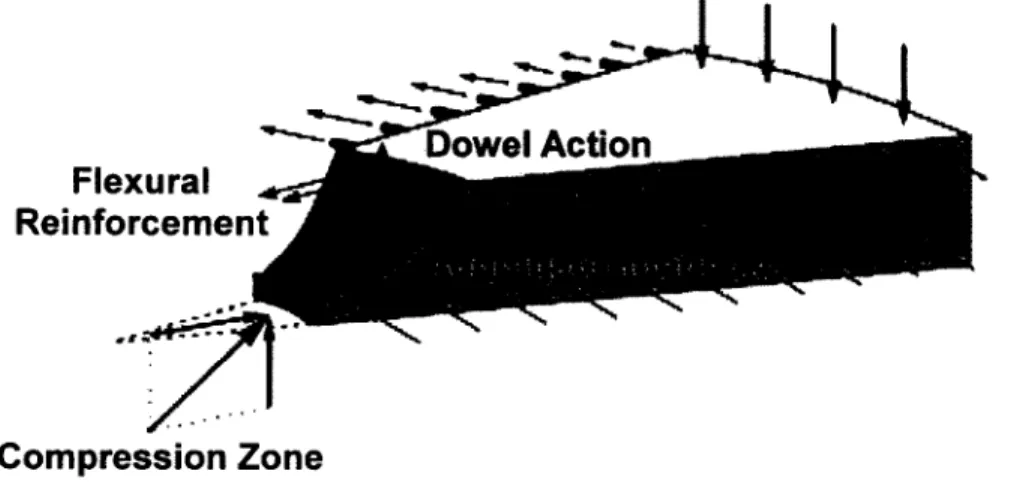
Figure 2.7: Shear failure mechanism in a cracked RC slab section without shear reinforcement (Adapted from Muttoni 2008)...16
Figure 2.8: Typical symmetrical punching failure around an interior column (Sherif 1996)... 17
Figure 2.9 : Failure modes in flat slabs: (a) crushing o f concrete struts; (b) punching within the shear-reinforced zone; (c) punching outside the shear-reinforced zone; (d) delamination; and (e) flexural yielding (Ruiz and Muttoni 2010)... 19
Figure 3.1: Sand-coated GFRP b a rs...31
Figure 3.2: Typical tension testing o f GFRP bar: (a) Test setup; (b) GFRP bar ru p tu re... 31
Figure 3.3: Typical stress-strain relationships for the reinforcing b ars...32
Figure 3.4: Details and configurations o f investigated stirrups...33
Figure 3.5: Dimensions o f the C-shaped specimens for B.5 test m eth o d ... 34
Figure 3.6: Preparation o f the test specimens... 34
Figure 3.7: Casting o f the concrete blo ck s...35
Figure 3.8: B.5 method test setup... 36
Figure 3.9: Rupture o f the FRP stirrups at the com er in concrete blocks followed by stirrups slippage... 37
Figure 3.10: Load-strain relationships at different locations o f the bend radius... 38
Figure 3.11: Compression test o f the standard concrete cylinders... 40
List o f Figures
Figure 3.13: Stress-strain relationship for different concrete batches...41
Figure 3.14: Typical details for specimens without shear reinforcem ent... 44
Figure 3.15: Specimen G(i.2)200 [reference slab o f Group II (1 )]... 45
Figure 3.16: Specimen G(i 2)200-GGS(d/2) (closed stirrups)... 46
Figure 3.17: Specimen G(i 2)200-CCS(d/2) (closed stirrups)... 47
Figure 3.18: Typical details for specimens with spiral stirru p s...48
Figure 3.19: Specimen G(i.2)30/20 (without bottom reinforcem ent)...49
Figure 3.20: Specimen G(i 6>30/20-B (with GFRP bottom reinforcement crossing the column cross-section)...49
Figure 3.21: Specimen G(o 3)30/35 (with low flexural reinforcement ratio)... 50
Figure 3.22: Specimen G(i.6)30/35 (with high flexural reinforcement ratio)...50
Figure 3.23: Specimen G(i.2)200-GCS(d/2)...51
Figure 3.24: Specimen G0 2)200-CCS(d/2)...51
Figure 3.25: Specimen G(03)350-GSS(d/4)...52
Figure 3.26: Specimen G(i 6)350-GSS(d/4)...52
Figure 3.27: Specimen G(, 6)350-GBSS(d/4)... 53
Figure 3.28: Specimen G(1 6)350-CSS(d/4)...53
Figure 3.29: Shuttering and fabrication o f the test specim ens... 56
Figure 3.30: Concrete casting o f the test specim ens... 57
Figure 3.31: LVDTs and concrete gauges placing in the top and bottom sides ...59
Figure 3.32: Crack width LVDTs placing...60
Figure 3.33: A photograph for the deflection measurement using LVDTs... 61
Figure 3.34: Measuring the initial flexural crack width using the hand-held m icroscope 62 Figure 3.35: A photograph for the placing o f the crack widths measurement using LVDTs ...62
Figure 3.36: GFRP bars electrical strain gauges...63
Figure 3.37: FRP closed stirrups electrical strain g au g es...63
Figure 3.38: FRP spiral stirrups electrical strain gauges...63
Figure 3.39: Concrete electrical strain gauges in the slab bottom s id e ...64
Figure 3.40: Temporary steel supports and the loading units placing...65
Figure 3.41: Placing the rigid steel frame on slab ...65
List o f Figures
Figure 3.43: A photograph o f the test setup o f the tested specim ens...66
Figure 4.1: Geometry, reinforcement configuration, and instrumentation... 72
Figure 4.2: Test setup: (a) Schematic and dimensions; (b) Testing o f a slab prototype... 75
Figure 4.3: Crack pattern and punching-shear failure surface (bold lines)...77
Figure 4.4: Failure surface distance o f the GFRP-reinforced prototypes...78
Figure 4.5: Cross-section o f slab prototypes after failure showing the critical shear crack 79 Figure 4.6: Normalized punching-shear stress at failure versus the axial stiffness o f the reinforcement o f the test prototype with a column dimension o f 300 mm [11.8 in.] 81 Figure 4.7: Load-deflection response: (a) Series I (200 mm [7.9 in.]); (b) Series II (350 mm [13.8 in.])... 83
Figure 4.8: Relationships between the post-cracked stiffness and the axial stiffness o f the reinforcement. (Note: 1 mm = 0.0394 in)... 83
Figure 4.9: Load-reinforcement strain relationships... 84
Figure 4.10: Reinforcement strain profile. (Note: 1 kN = 0.225 k ip .)...85
Figure 4.11: Crack width relationships... 86
Figure 5.1: Geometry and reinforcement configuration...97
Figure 5.2: Fabrication o f the test specimens: a) Reinforcing cages; b) Concrete c astin g 99 Figure 5.3: Instrumentation p la n ... 100
Figure 5.4: Test setup: (a) Schematic and dimensions; (b) Specimen testing...101
Figure 5.5: Typical punching-shear failure for the tested specim ens... 103
Figure 5.6: Load-deflection responses: (a) Series I; (b) Series II; (c) Series III; (d) Series IV ...106
Figure 5.7: Normalized punching shear stress versus average effective depth...107
Figure 5.8: Normalized punching-shear stress at d/2 from column face versus the reinforcement axial stiffness...108
Figure 5.9: Effect o f b j d on the shear strength o f the test specim ens...109
Figure 5.10: Punching-shear stress at d!2 from column face versusf ' c...109
Figure 5.11: Load-reinforcement strain relationships... 111 Figure 5.12: Reinforcement strain profile: (a) Specimen G(o.7)30/35; (b) Specimen
List o f Figures
Figure 6.1: Test specimens’ geometry, reinforcement configuration, and instrum entations...123 Figure 6.2: Test setup: (a) Schematic and dimensions; (b) Testing o f a specim en... 125 Figure 6.3: Typical punching-shear failure and main shear crack for some specimens... 128 Figure 6.4: Normalized punching-shear stress at 0.5d from the column face versus the
effective reinforcement ratio...130 Figure 6.5: Load-deflection relationships: (a) Series I; (b) Series II... 132 Figure 6.6: Load-strain reinforcement and concrete relationships: (a) Series I; (b) Series I I . 134 Figure 6.7: Reinforcement strain profiles for some tested specimens... 135 Figure 6.8: Tested-to-predicted capacity versus effective reinforcement ratio... 139 Figure 7.1: Test specimens’ geometry, reinforcement configuration and
instrumentations: a) G/CSS and GBSS; b) CCS; c) GCS; d) slabs without shear reinforcem ent... 149 Figure 7.2: Details and configurations o f investigated stirrups... 151 Figure 7.3: Test setup and instrumentation: (a) Supports and loading jacks; (b)
Schematic; (c) LVDTs locations; (d) Instrumentation details... 154 Figure 7.4: Final punching-shear failure surface for the tested specimens (in Bold)...156 Figure 7.5: Cross-section failure envelop... 160 Figure 7.6: Load-deflection relationships o f the test specimens (LVDT placed @ 40mm
in X direction)...162 Figure 7.7: Load-flexural strains relationships: (a) Series I; (b) Series II...164 Figure 7.8: Strain profile in the flexural reinforcement at 0.95 Vu: (a) Series I; (b)
Series II...164 Figure 7.9: Stirrups strains in the straight portion located at d/2 and d perimertes: (a)
Series I; (b) Series II ...166 Figure 7.10: Strain profile in the straight portion o f the stirrups at 0.95 Vu: (a) Series I;
List o f Symbols
LIST OF SYMBOLS
SI units are used throughout this study presented herein. Unless otherwise stated, the symbols most frequently used have the following meanings:
Symbol Definition
A f total area o f the reinforcing bars in one direction;
Af, Ave. average area o f the reinforcing bars in the two directions;
Arx area o f steel or FRP flexural reinforcement in X direction (mm2);
cross-sectional area o f the FRP shear reinforcement on a concentric line parallel to the perimeter o f the column;
b O;0.5d critical perimeter at a distance o f 0.5d from the column face (mm); b o:1.5d critical perimeter at a distance o f 1.5d from the column face (mm);
d average effective slab depth (mm) = slab thickness — 50/or 45 mm — db,
dx effective slab depth in X directions (mm); dx=t-db/2-50/or 45 mm;
d y effective slab depth in Y directions (mm); <iy=t-l ,5 ^-5 0 /o r 45 mm;
db reinforcing bar diameter (mm);
E r modulus o f elasticity o f the tensile reinforcing bars (MPa); E s modulus o f elasticity o f steel reinforcing bars (MPa); E f modulus o f elasticity o f FRP reinforcing bars (MPa);
Ejv modulus o f elasticity o f FRP stirrups straight portion (MPa); E c modulus o f elasticity o f the concrete (MPa) ( = 4 7 5 0 ) ; E jA f FRP flexural reinforcement axial stiffness (N);
f c cylinders concrete compressive strength (MPa); f t split cylinder tensile strength o f concrete (MPa); f u ultimate tensile strength o f steel bars;
f y yield strength o f steel bars;
List o f Symbols
f l u ' guaranteed tensile strength FRP bars (MPa);
ultimate tensile strength o f the straight portion o f FRP stirrups (MPa);
fjv b ultimate tensile strength o f FRP stirrups at bend location (MPa);
nf modular ratio ( E / E c);
ns numbers o f stirrups on a concentric line parallel to the perimeter o f the column;
radius o f the bend (mm);
stirrup spacing, shall not exceed d/2, with the first stirrup placed at d/4 from the column face according to (CSA 23.4-2004);
t slab thickness (mm);
u perimeter o f the loaded area (mm);
Vu. ultimate shear stress at the column face (MPa);
Vu, 0.5d ultimate shear stress at d/2 from the column face (MPa);
V c ultimate punching-shear stress provided by the concrete (MPa);
V ultimate punching-stress provided by the FRP shear reinforcement (MPa);
V u ultimate/peak punching shear load (measured in test) (kN); V C ultimate punching shear capacity provide by the concrete (kN); Vcr first radial cracking load (kN);
Vtang. tangent cracking load (measured in test) (kN);
V ju post-peak load (kN);
X cone distance from the column face to the observed failure surface;
X efm ax distance from the column face to the maximum strains in the FRP bars; &xcone estimated angel cone calculated from the Xcone distance in the horizontal
direction = (tan’I(t/A'C0,K,);
O-cone actual average punching shear-angle cone in the horizontal direction;
a a new parameter function for FRP tensile stiffness;
X factor to account for concrete density (A=l for normal-density concrete);
as factor that adjusts V c for support dimensions;
P c the ratio o f long side to short side o f the concentrated load or reaction area;
List o f Symbols
A \u deflection at the peak load (mm); Au defection at failure (post-peak) (mm);
P reinforcement ratio;
Pb balanced reinforcement ratio;
P f FRP reinforcement ratio = A f Ave / ( 2 5 0 0 * d);
Ps steel reinforcement ratio = A f Ave. / (2500><£/);
Pfb FRP bars balanced reinforcement ratio calculated according to A C I4 4 0 .1R
(2006);
Pfv shear reinforcement ratio at a perimeter at 0.5d; = (ns*AfdSjv.bo;o.sa);
P fvE fv shear reinforcement index;
<t>c material resistance factor for concrete;
By yield strain o f steel bar (ps);
Efu ultimate tensile strain for FRP bar (ps);
Bfl'u ultimate tensile strength o f FRP bars at peak load (pe);
Bfmax maximum tensile strength o f FRP bars at the post-peak load (ps); Bcmax ultimate concrete strength (pe);
C h apter I ; Introduction
CHAPTER 1
INTRODUCTION
1.1 Background and Problem Definition
The expansive corrosion o f steel reinforcing bars is a significant factor shortening the service life o f reinforced concrete (RC) structures. The deleterious effects due to significant temperature fluctuations, de-icing salts, and chlorides have created harsh environment conditions accelerating the corrosion o f steel reinforcement in concrete structures such as parking garages. Furthermore, the expansive corrosion o f steel causes cracking and spalling of the concrete cover, which typically lead to significant deterioration and rehabilitation needs. Several methods have been proposed to control the corrosion process by means o f stopping chlorides and carbonation attack reaching to the surface o f the steel and/or making the steel corrosion-resistant, for instance, increasing the concrete cover, decreasing the permeability o f concrete, waterproofing membranes, epoxy coating, and galvanizing and stainless steel bars (Broomfield 2007). None o f these techniques, however, has been proven to be cost-effective or a long-term solution.
A significant research effort over the past twenty years has shown that fibre-reinforced polymer (FRP) reinforcing bars can be used effectively as an alternative to the steel bars in RC structures, particularly where steel corrosion is a major concern. FRPs are corrosion-free and nonmagnetic materials with high strength-to-weight ratios, in addition to their possibility to provide embedded microwire sensors into the matrix (used as a kind o f “smart” reinforcement) (Komova et al. 2008), makes them an attractive alternative reinforcement for concrete structures. Using FRP reinforcing bars in RC two-way slabs such as in parking garages, the most component structural element vulnerable to corrosion deteriorations because o f the direct exposure to high concentration o f chlorides used for snow and ice removal, can extend the lifetime serviceability, reduce maintenance costs, and improve life-cycle cost efficiency.
C h apter 1: Introduction
Moreover, FRP bars may also reduce construction costs by eliminating the need for waterproofing membranes and pavement items (Benmokrane et al. 2006).
Since glass FRP (GFRP) bar is more economical than the available types (carbon and aramid) o f FRP bars, it is more attractive for the construction industry. Furthermore, recent advances in polymer technology have led to the development o f a new generation o f GFRP bars designated with high modulus o f elasticity, which is expected to advance the use o f GFRP reinforcing bars in many applications. Several successful field applications have been built with GFRP bars as internal reinforcement, especially concrete bridge deck slabs (El-Salakawy et al. 2005, and Benmokrane et al. 2006 & 2007). However, to date, the number o f practical applications in two-way flat slabs parking garages reinforced internally w ith GFRP bars is very limited because o f insufficient knowledge o f the punching-shear behaviour o f FRP-RC two-way flat slabs.
The shear design o f RC flat slabs structures has received a great challenge for decades. The shear failure o f the slab-column connection, commonly known as punching-shear failure, can lead to catastrophic collapse o f the entire floor system (Cheng and Parra-Montesinos 2010). Punching-shear failure o f slabs without shear reinforcement is brittle in nature with limited deflections and followed by a sudden loss o f the load-carrying capacity. Several ways can be used to increase the punching-shear capacity of RC two-way slabs such as increasing slab thickness and/or column dimensions, using drop panels and/or column heads or both, concrete compressive strength ( f c), and placing shear reinforcement in the punching-shear zone o f the slab. The well-designed punching-shear reinforcement significantly improves the slab behaviour, as it not only increases the punching-shear strength but also the deformation capacity o f the slab (Lips et al., 2012). The principle effect o f the shear reinforcement is to restrain the discontinuity o f the slabs at the shear crack and transfers most o f the forces across the shear crack, which delays the further widening o f the shear crack, thus increasing the punching-shear and deformation capacity (Rizk et al. 2011). Moreover, using the shear reinforcement in two-way flat slabs is a preferred way when the increase in slab thickness is restricted which, in turn, reduces the slabs self-weight, the total height, and the overall cost o f the structure.
The FRP mechanical properties have a brittle linear elastic response, a lower modulus o f elasticity, and different bond characteristics than that o f steel reinforcement, which results
C h apter I: Introduction
in differences in the punching-shear behaviour. Few studies were conducted to evaluate the punching-shear behaviour o f FRP bars and/or grids in RC two-way slabs reinforced with and without FRP shear reinforcement (Ahmad et al. 1993; Banthia et al. 1995; Matthys and Taerwe, 2000 a & b; El-Ghandour et al. 2003; Ospina et al. 2003; Hussein et al. 2004; Zhang et al. 2005; Zaghloul 2007; Lee et al. 2009, and Nguyen-Minh and Rovank 2013). Through these investigations, it was demonstrated that the difference in mechanical properties and bond characteristics between FRP and steel reinforcement significantly affect the slab behaviour and strength. This results in the development o f wider and deeper cracks. Deeper cracks decrease the contribution to shear strength from the uncracked concrete due to the lower depth o f concrete in compression. Wider cracks, in turn, decrease the contributions from aggregate interlock and residual tensile stresses. Additionally, due to the relatively small transverse strength o f FRP bars and relatively wider cracks, the contribution o f dowel action may be negligible (El-Gamel et al. 2005 b). Besides, given the difference in mechanical properties, the punching-shear equations for steel-RC flat slabs cannot be directly employed for FRP-RC sections.
Most o f the current equations predicting the punching-shear strength o f FRP-RC elements are modified forms o f those for steel-reinforced elements, in which an equivalent FRP ratio was included to account for the lower elastic stiffness of FRP bars. Recently, the Canadian Standard Association provided its first equations for predicting the punching-shear strength o f FRP-RC members without shear reinforcement in the CAN/CSA S806-12 (2012), which provides a step forward for the design o f such elements. These equations are based on the CSA A23.3 (2004) equations for a steel-reinforced section with some modifications to account for the FRP axial stiffness as well as the cubic root o f the concrete compressive strength was proposed. Nevertheless, no codes and design guidelines or rational design models addressed the contribution o f the FRP as shear reinforcement (stirrups) for FRP-RC two-way slabs. In addition, the use o f FRP as shear reinforcement in two-way flat slabs was not fully investigated. Thus, this extensive experimental study is designed to investigate the punching shear behaviour o f GFRP-RC two-way flat slabs reinforced with and without FRP shear reinforcement (stirrups) under concentric loading.
C h apter I: Introduction
1.2 Research Significance
This research project examines the punching shear behaviour o f interior two-way slab- column connections reinforced with GFRP bars under concentric loading. In addition, it pays attention to use o f glass and carbon fiber-reinforced polymer (GFRP and CFRP) closed and spiral stirrups as shear reinforcement to enhance the punching-shear capacity o f GFRP two- way slabs. The effects o f most relevant parameters influencing the punching-shear capacity such as flexural reinforcement ratio and type, GFRP compression reinforcement, slab thickness, column dimensions, concrete strength (normal- and high-strength concretes), and FRP shear reinforcement contribution were also investigated.
The results o f this research has contributed to implementing the GFRP bars in parking structures, which is an innovative solution o f the corrosion problem of parking garages’ slabs (Benmokrane et al. 2012). On the other hand, it introduces experimental results on the effects o f FRP flexure and shear reinforcement on punching-shear capacity of flat slabs. The accuracy o f current equations in the FRP design codes and guidelines (CSA S806 (2012); ACI 440 (2006); BS 8110 (1997) and JSCE (1997), and other design approaches from the literature were assessed. This research work also enriches the state-of-the-art and the databank o f concentric punching shear tests o f GFRP two-way slabs as well as provides useful information to all researchers and practicing engineers.
1.3 Objectives and Originality
The GFRP reinforcing bars are standing out as a realistic and cost-effective alternative reinforcement to conventional steel bars for concrete structures under severe environmental conditions. However, to date, the number o f practical applications in RC two-way slabs parking garages reinforced internally with GFRP bars is very limited because o f the lack o f research and data on the punching-shear behaviour o f FRP-RC two-way slabs. Besides, most o f the experiments on slab-column connections conducted to date are based on slabs with a thickness o f around 175 mm and a concrete strength ranging from 26 M Pa to 50 M Pa while few specimens constructed with high strength concrete (HSC) as well as FRP shear reinforcement. Therefore, more experimental results on slab-column connections are needed to clearly understand the structural performance o f such elements.
C h apter I : Introduction
Through the Natural Sciences and Engineering Research Council o f Canada (NSERC) Industrial Research Chair in FRP for Concrete Infrastructure at the University o f Sherbrooke, a joint effort with the Ministere du Developpement Economique, de l'lnnovation et de l'Exportation (MDEIE) o f Quebec was established to develop and implement GFRP reinforcement bars for RC two-way slabs parking garages. This effort was initiated by evaluating the punching-shear behaviour o f GFRP-reinforced interior slab-column connections without FRP shear reinforcement (Phase I) and with FRP shear reinforcement (stirrups) (Phase II) focusing on evaluating their contribution on the punching-shear capacity.
Recently, the CAN/CSA S806-12 (2012) has published its new equations for predicting the punching-shear strength o f FRP-RC members without shear reinforcement, which provides a step forward for the design an application o f such elements. The accuracy and the validity o f these equations as well as other available equations in the design guidelines and the literature will be evaluated. The main objectives o f the current investigation can be summarized as follow:
1. To investigate the punching-shear behaviour o f GFRP-RC two-way flat slabs with and without FRP shear reinforcement under concentric loading.
2. To investigate the FRP-stirrups’ contribution to the punching-shear capacity o f the GFRP-RC two-way flat slabs.
3. To evaluate the accuracy o f the new proposed equations in the CAN/CSA S806-12 (2012) design code and current equations in the design guidelines for punching shear strength o f FRP two-way flat slabs.
4. To establish design recommendations for the use o f FRP materials as flexural and shear reinforcement in two-way flat slabs parking garages.
1.4 Methodology
Experimental and analytical studies were designed to achieve the aforementioned objectives o f this research. The experimental study comprised two phases (Phase I and II). The two phases included construction and testing o f twenty-six full-scale interior slab-column connections reinforced with GFRP bars and two specimens reinforced with steel bars for comparisons. Whereas, the first Phase I included twenty-one specimens without shear reinforcement, and Phase II included seven specimens with FRP shear reinforcement. The test
C h apter 1: Introduction
specimens were designed to simulate real thicknesses o f flat slabs being used in the first implementation for GFRP bars in two-way flat slab parking garages (Benmokrane et al. 2012). Each specimen had a side dimension o f 2500 mm in both directions and a central column stub extending 300 mm beyond the top and bottom surfaces o f the slabs. The test specimens were simply supported along all four edges. A concentric load was applied to the slabs through the column stub from down. Through the experimental program, the effects o f the following parameters were investigated: (i) flexural reinforcement ratio (ranged from 0.34% to 1.66%) and type (steel and GFRP); (ii) GFRP compression reinforcement; (iii) slab thickness (200 mm and 350 mm); (v) column dimensions (300 x 300 mm and 450 x 450 mm); (iv) concrete strength (normal and high-strength concretes); (vi) FRP shear reinforcement contribution.
On the other hand, the analytical study included assessing the accuracy o f the current punching-shear design provisions through comparing the test results o f the specimens tested herein and 35 specimens from literature. The provisions included CSA S806-12 (2012), ACI 440 (2006), BS 8110 (1997), and JSCE (1997).
1.5 Organization of the Dissertation
This dissertation consists o f eight chapters. The following is a brief description o f each:
Chapter 1: This chapter defines the problem and summarizes the main objectives and
originality o f the research program. The methodology followed to achieve these objectives is also emphasized.
Chapter 2: This chapter provides brief description o f the FRP composites materials and their
characteristics. The available literature review focusing on the punching-shear behaviour o f the FRP two-way slabs reinforced with and without FRP shear reinforcement is also presented. The available punching-shear design provisions for concrete members reinforced with FRP recently introduced in Japan, Europe, USA, and Canada are also presented.
Chapter 3: This chapter describes the experimental program conducted at the University o f
C h apter 1: Introduction
reinforcement. In this chapter, the details o f test specimens, configurations, test setups, and instrumentations are given. The chapter provides detailed characteristics o f the materials used in this research program.
Chapter 4: This chapter presents the first paper in this dissertation entitled “Punching-Shear
Behavior o f Flat Slabs Reinforced with Glass Fiber-Reinforced Polymer Bars.” The presented materials in this chapter are collaborative joint research work between the author o f this dissention during his doctorate studying and a master candidate (Dulude 2011). The experimental work is based on testing 10 interior slab-column connections without shear reinforcement with five specimens o f each author. Factors influencing the punching-shear strength and deformation capacity such as the effect o f reinforcement type (GFRP and steel) and ratio, slab thickness and column dimensions are addressed. Additionally, the test results are employed to evaluate the accuracy o f current equations predicting the punching-shear strength o f FRP-RC two-way slabs provided by codes, design guidelines, and others models from the literature are presented.
Chapter 5: This chapter presents the second paper in this dissertation entitled “Punching-Shear
Strength o f GFRP-Reinforced Concrete Flat-Slabs.” The experimental study was extended to complete the test matrix presented in the first paper. The punching-shear behaviour o f 17 test specimens without shear reinforcement divided into 4 Series was discussed and analysed. Extended parameters such as concrete strength (30 to 47 MPa) and GFRP compression reinforcement crossing the column cross section were highlighted. Comparisons between the experimental test results and the theoretical predictions values by the Canadian Standards code CSA S806-12 (2012), design guidelines and other models from the literatures are performed.
Chapter 6: This chapter presents the third paper in this dissertation entitled “Punching-Shear
Strength o f Normal and High-Strength Concrete Slabs Reinforced with GFRP Bars” In this study, a total o f 10 full-scale interior slab-column connections without shear reinforcement were fabricated with normal- and high-strength concretes. The main objective o f this paper is to investigate the punching-shear behaviour o f two-way flat slabs reinforced with different grades o f GFRP bars and constructed with different concrete grades (NSC and HSC).
C h apter 1: Introduction
Comparisons between 54 specimens without shear reinforcement tested to date including the specimens in this investigation, using punching-shear design models presented in CSA S806 (2012), ACI 440 (2006), BS 8110 (1997), and JSCE (1997) were assessed.
Chapter 7; This chapter presents the fourth paper in this dissertation entitled “Punching Shear
Behavior o f GFRP Reinforced Concrete Slabs Using FRP Shear Reinforcement.” It presents the results o f an experimental investigation on the behaviour o f GFRP-RC two-way flat slabs reinforced with and without FRP shear reinforcement. A total o f 10 full-scale interior slab- column connections were tested under concentrated load up to failure. The tests were performed to evaluate the effectiveness and contribution o f using the FRP as shear reinforcement in the GFRP-RC slabs.
Chapter 8: A summary o f this investigation is given in this chapter. The chapter also presents
the general conclusions drawn from the work presented in this dissertation. Recommendations for future research are also given.
Although the complete description o f the research work conducted herein was presented and discussed in the four papers listed above, more information was introduced in Appendix A concerning the failure envelop for all the test specimens.
C h apter 2: Literature R eview
CHAPTER 2
LITERATURE REVIEW
2.1 General
In many parts o f the world, corrosion o f steel reinforcement in concrete structures is a major durability problem, leading to structural degradation and consequent costly repairs and loss o f serviceability. In the recent decade, the use o f advanced composites, normally called fiber reinforced polymers (FRP), as reinforcement for concrete structures has emerged as one o f the most promising new technologies in construction to overcome the problem o f corrosion. Several design guides and codes on reinforcing structural concrete members with FRP reinforcement were developed and published in several countries (JSCE (1997); ISIS design manual No. 3 (2007); CSA S6-06 (2006); ACI 440.1R-06 (2006); CNR-DT 204-06 (2006); FIB Task Group 9.3 (2007); and CSA S806-12 (2012). Countries such as, Canada, United States (USA), Japan and some other European countries have already implemented the use o f FRP in bridges deck slabs, parking structures, barrier walls, continuous pavement, and other concrete structures.
This chapter provides brief information on the FRP materials and their characteristics. The previous research studies carried out to investigate the punching-shear behaviour o f FRP- reinforced concrete two-way slabs with and without FRP shear reinforcement are reviewed. The punching-shear design provisions for concrete two-way slabs reinforced with FRP recently published in Japan, Europe, USA, and Canada are also presented.
2.2 FRP Composite Materials
“FRP” is an acronym for fiber reinforced polymers, which some also call fiber reinforced plastics. The term composite material is a generic term used to describe a judicious combination o f two or more materials to yield a product that is more efficient from its constituents. One constituent is called the reinforcing or fiber phase (one that provides
C h apter 2: L iterature R eview
strength); the other in which the fibers are embedded is called the matrix phase. The matrix, such as a cured resin-like epoxy, polyester, vinyl ester, or other matrix acts as a binder and holds the fibers in the intended position, giving the composite material its structural integrity by providing shear transfer capability. Figure 2.1 shows typical stress-strain curves for fibers, matrices, and the FRP materials that result from the combination o f fibers and matrix.
Stress [Mpa] fibres 1 8 0 0 4 9 0 0 -600-3000 FRP matrix 34-130 Strain 0 . 4 - 4 .8 > 10 [%]
Figure 2.1: Stress-strain relationships for fibres, matrix, and FRP ISIS design manual No. 3 (2007)
Three FRPs are commonly used (among others): composites containing glass fibers are called glass fiber reinforced polymers (GFRP); those containing carbon fibers are called carbon fiber reinforced polymers (CFRP); and those reinforced w ith aramid fibers are referred to as aramid fiber reinforced polymers (AFRP). GFRPs are the most inexpensive compared to the other commercially available FRPs, consequently the most commonly used fibers in structural engineering applications.
Use o f composite materials was pioneered by the aerospace industry beginning in the 1940s, primarily because o f the material’s high-performance and lightweight qualities. Today their potential is being harnessed for many uses. Advanced composite materials, so called because o f their many desirable properties, such as high performance, high strength-to-weight and high stiffness-to-weight ratios, high-energy absorption, and outstanding corrosion and fatigue damage resistance are now increasingly used for civil engineering infrastructure such as buildings and bridges. FRP products are manufactured in different forms such as bars,
C h apter 2: L iterature R eview
fabrics, 2D grid, 3D grid, or standard structural shapes. Figure 2.2 shows various types and shapes o f currently available FRP products.
Figure 2.2: Different FRP products: (a) fabrics and strips; (b) straight bars; (c) grids; (d) spiral stirrups and curved bars.
2.3 General Characteristics of FRP Reinforcing Bars
FRP reinforcing bars are manufactured from continuous fibers (such as carbon, glass, and aramid) embedded in matrices (thermosetting or thermoplastic). A key element in evaluation o f FRP properties is the characterization o f the relative volume and/or mass content o f the various constituent materials. The FRP reinforcing bars in concrete structures is strongly
C h apter 2: Literature R eview
influenced by their physical and mechanical properties. Available design variables include the choice o f constituents (fiber and polymeric matrix), the volume fractions o f fiber and matrix, fiber orientation and the manufacturing process. Other factors such as dimensional effects and quality control during fabrication play an important role in determining the characteristics o f FRP bars. The properties o f FRP materials are also influenced by loading history, duration o f loading, temperature and humidity.
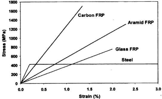
Similar to steel reinforcement, FRP bars are produced in different diameters, depending on the manufacturing process. FRP bars normally have tensile strength higher than the tensile strength o f conventional steel bars. This relatively high tensile strength makes FRP bars suitable as reinforcement for concrete structures. The tensile behaviour o f FRP bars having one type o f fiber material is characterized by a linearly elastic stress-strain relationship up to failure. They do not exhibit any plastic behaviour before rupture. Typical tensile stress- strain relationships o f FRP reinforcement compared to conventional steel bars are shown in Figure 2.3. The figure also shows that the modulus o f elasticity o f FRP bars is lower than that o f steel bars. The CFRP has the highest modulus o f elasticity, which ranged from 60% to 75% o f that for steel. While the GFRP bars has the lowest modulus o f elasticity, which ranged from 20% to 25% o f that for steel. Table 2.1 shows the mechanical properties o f some commercially available FRP reinforcing bars.
1800 1600 Carbon FRP 1400 Aramid FRP 1200 S 1000 <0 « 800 Glass FRP fi « 600 Steel 400 200 1.8 2.0 2.5 3.0 1.0 0.0 0.5 Strain (%)
C hapter 2: Literature R eview
Bond behaviour o f an FRP bar depends on the surface preparation and mechanical properties o f the bar itself as well as the environmental conditions. The FRP bars surface preparations can be divided into two general categories according to the technique in which bond stresses between the FRP bar and the concrete are transferred, friction forming preparations and bearing forming preparations. The bars in the first category are coated with a granular material before the bars completely cured. These granular particles increase bond transfer through friction between the bars and concrete. Another way o f increasing the bond strength o f the bars is through the formation o f indentations or deformations on the bar before full curing. The V-ROD FRP bars; which have sand-coated surface and are produced by Pultrall Inc., Quebec, Canada, stand as example o f the bars o f first category, whereas Leadline™ CFRP bars; which have indented surface and are produced by Mitsubishi Chemical Cooperation, Japan, stand as example o f the bars o f second category. On the other hand, the surface o f the Aslan FRP bars produced by the Hughes Brothers Inc., USA, contains indentations as well as a granular coating. Figure 2.4 shows different surfaces types o f sand- coated and deformed FRP bars.
Figure 2.4: Different surfaces types o f FRP bars
Further information concerning the physical and mechanical properties, time dependent behaviour, and durability o f FRP reinforcement, can be found in the following:
C h apter 2: L iteratu re R eview
JSCE (1997); ACI 440.1R-06 (2006); ISIS design manual No. 3 (2007); CAN/CSA-S806 (2012), S807 (2010), and S6-06 (2006).
Table 2.1: Typical mechanical properties o f FRP reinforcement bars
Trade name Fiber type
Guaranteed tensile strength (MPa) Modulus o f elasticity (GPa) Ultimate tensile strain (%) V- RO D 1 Carbon 1356-1765 120-144 1.18-1.13 V- ROD LM 1 Glass 666-804 43-45 1.34-1.89 V- ROD SM 1 Glass 703-941 53-57 1.33-1.79 V- ROD H M 1 Glass 1000-1372 63-66 1.15-2.11 Aslan 2002 Carbon 2068-2241 124 1.17-1.81 Aslan 1002 Glass 551-896 46 1.19-1.94 ComBARJ Glass > 1000 > 6 4 1.17 Leadline4 Carbon 2250 147 1.50 RockBAR5 Basalt 1107-1350 43-48 2.72-3.10
Dost Re-Bar6 Carbon 2300’ 130 1.80
Dost Re-Bar6 Aramid 1400* 60 2.40
Dost Re-Bar6 Glass 1000’ 40 2.8
2
3 4 5 6
Pultrall Inc. ( http://www.pultrall.com).
Hughes Brothers Inc. ( http://www.aslanfrp.com ). Schock Inc. ( http://w w w .schoeck.ca).
Mitsubishi Chemical Coporation Inc.(ISIS manual 3, 2007). Kammeny V ek Inc. (Serbescu, A. 2009).
DostKim ya Inc. (http://w w w .dostkim va.com ): (*) tensile strength.
2.4 Shear Strength of Concrete Two-Way Slabs
Shear failure o f concrete two-way slabs in the vicinity o f concentrated loads may be due to beam action or two-way action. In case o f the beam action, the slab behaves as a wide beam and the failure surface extends along the entire width o f the slab. This type o f failure occurs rarely in flat slab system.
In case o f two-way action, the slab fails in a local area around the concentrated load. The critical section extends around the concentrated load or column. A punching shear failure occurs along a truncated cone or pyramid caused by the critical diagonal tension crack around the concentrated load or column. Figure 2.5 shows the slab shear-failure mechanisms.
C h apter 2: L iterature R eview .Pyramid-shaped failure surface In c lin e d c r a c k v (b) Two-way shear (a) One-way shear
Figure 2.5: Shear-failure in a slab (MacGregor 1997)
Shear failure at a slab-column connection can result in progressive failures o f adjacent connections o f the same floor, as the load is transferred elsewhere, causing the adjacent connections to be more heavily loaded. In addition, the lower floor may fail progressively as they become unable to support the impact o f material dropping from above. Hence, caution is clearly needed in shear strength calculation, and attention should be given to the low ductility associated with shear strength in order to avoid brittle failure conditions if possible.


![Figure 3.15: Specimen G(i.2)200 [reference slab o f Group II (1)]](https://thumb-eu.123doks.com/thumbv2/123doknet/5604696.134914/69.920.171.760.94.933/figure-specimen-g-i-reference-slab-group-ii.webp)