OATAO is an open access repository that collects the work of Toulouse
researchers and makes it freely available over the web where possible
Any correspondence concerning this service should be sent
to the repository administrator:
[email protected]
This is an author’s version published in: http://oatao.univ-toulouse.fr/21732
To cite this version:
Tortei, Daniel
and Fillatreau, Philippe
and Piat, Jonathan
and
Brenot, François
and Devy, Michel
HW/SW co-design of a
visual SLAM application. (2018) Journal of Real-Time Image
Processing. 1-23. ISSN 1861-8200
HW/SW co‑design of a visual SLAM application
Jonathan Piat1,2 · Philippe Fillatreau4 · Daniel Tortei1,2 · Francois Brenot1,3 · Michel Devy1
Abstract
Vision-based advanced driver assistance systems (ADAS), appeared in the 2000s, are increasingly integrated on-board mass-produced vehicles, as off-the-shelf low-cost cameras are now available. But ADAS implement most of the time-specific and basic functionalities such as lane departure or control of the distance to other vehicles. Integrating accurate localization and mapping functionalities meeting the constraints of ADAS (high-throughput, low-consumption, and small-design footprint) would pave the way towards obstacle detection, identification and tracking on-board vehicles at potential high speed. While the SLAM problem has been widely addressed by the robotics community, very few embedded operational implementations can be found, and they do not meet the ADAS-related constraints. In this paper, we implement the first 3D monocular EKF-SLAM chain on a heterogeneous architecture, on a single System on Chip (SoC), meeting these constraints. In order to do so, we picked up a standard co-design method (Shaout et al. Specification and modeling of hw/sw co-design for heterogeneous embedded systems, 2009) and adapted it to the implementation of potentially any of such complex processing chains. The refined method encompasses a hardware-in-the-loop approach allowing to progressively integrate hardware accelerators on the basis of a systematic rule. We also have designed original hardware accelerators for all the image processing functions involved, and for some algebraic operations involved in the filtering process.
Keywords FPGA · Co-design · SLAM · Machine-vision · ADAS
1 Introduction
Advanced driver assistance systems (ADAS) appeared in the 2000s and are now increasingly found on-board mass-pro-duced vehicles. They involve various sensors (cameras, lidar, others) and signal or image processing functionalities (e.g. extraction and analysis of features detected in acquired sig-nals or images), see [33]. ADAS-related concepts have been notably validated by research on perception or navigation for autonomous mobile robots since the 1980s. Nevertheless, ADAS implement most of the time specific and independ-ent functionalities, such as the control of distance to other vehicles, or the detection of driver hypovigilance or lane departure, see [27]. Functionalities such as accurate vehicle localization and sparse vehicle environment mapping would allow paving the way towards obstacle detection, identifica-tion and tracking (notably thanks to the reducidentifica-tion of the complexity of the associated data processing) and towards autonomous navigation of road vehicles at high speed.
Self-localization and environment modelling have been central issues for research on mobile robots since the 1980s [10], although the SLAM acronym appeared towards the end
* Jonathan Piat [email protected] Philippe Fillatreau [email protected] Daniel Tortei [email protected] Francois Brenot [email protected] Michel Devy [email protected]
1 CNRS, LAAS, 7 avenue du colonel Roche, 31400 Toulouse,
France
2 Univ de Toulouse, UPS, LAAS, 31400 Toulouse, France 3 Institut National Polytechnique de Toulouse,
INPT - University of Toulouse, 4 Allee Emile Monso, 31030 Toulouse, France
4 Laboratoire Genie de Production de l’Ecole Nationale
d’Ingenieurs de Tarbes (LGP-ENIT), Institut National Polytechnique de Toulouse (INPT), University of Toulouse, 47 avenue d’Azereix, BP1629, 65016 Tarbes Cedex, France
of the 1990s [14]. Various sensors have been used for the associated perception tasks, e.g., ultrasonic sensors, laser range finders, and cameras. The emergence of off-the-shelf low-cost cameras allows using them in monocular, stereo-vision, or panoramic vision-based ADAS systems, see [18]. The simultaneous localization and mapping (SLAM) issue has now been widely explored by the robotics com-munity, and numerous academic solutions have been pro-posed. However, very few complete embedded operational chains meeting the constraints associated with ADAS (fast processing times, low-consumption, small-design footprint) can be found in the literature. This is partly due to the intrin-sic complexity of the advanced image processing algorithms involved and to the large volume of data (number of pixels) to be processed.
The computer vision and robotics perception communi-ties started in the late 1990s–early 2000s to study the design of specific, embedded and real-time architectures, involv-ing programmable logics, for advanced image processinvolv-ing functionalities, see [35]. Much progress remains to be done about vision-based SLAM, a complex image processing and numerical filtering chain. To embed such a complex functionality on an ADAS, one must explore the possibili-ties offered by available execution resources, to take advan-tage of their specific properties. This leads the designer to formulate a heterogeneous (or not) processing architecture involving both general purpose processing units and appli-cation-specific hardware accelerators. To define an efficient distribution of the computational load over these two kinds of operators, the design needs to be undertaken following joint design (called co-design) approaches.
This paper deals with the definition of a heterogeneous architecture for the integration of a complete monocular 3D extended Kalman filter (EKF) vision-based SLAM process-ing chain meetprocess-ing the constraints of an ADAS. To achieve that, we have studied the introduction of a suitable co-design methodology associated with a hardware-in-the-loop (HIL) approach allowing to progressively integrate specifically designed hardware accelerators.
The contribution is threefold :
• we have selected in the literature a standard and generic co-design approach [38] which we have (1) refined to allow the integration of a complex processing chain such as a vision-based monocular SLAM and (2) adapted to encompass a hardware-in-the-loop approach allowing to progressively integrate hardware accelerators; in our approach, the hardware accelerators are integrated one by one, based on the use of a systematic rule based on the results of the profiling of the heterogeneous SLAM chain under construction. The refinement and adapta-tion brought to the state-of-the-art method we picked up [38] are not specific to the nature of the processing chain
developed here, and can be reused for any advanced sig-nal or image processing chain.
• we have used this refined co-design method to integrate the first complete monocular 3D EKF-SLAM chain on a heterogeneous (hardware/software) architecture on a sin-gle SoC. The obtained performances meet the constraints (processing times, power consumption, design footprint) of the ADAS.
• we have developed and validated original hardware accel-erators (reusable for any embedded SLAM application or vision application involving the same functionalities) of all the image processing and of some data process-ing functions involved in the numerical filterprocess-ing steps (Fig. 1).
This work was conducted in the context of the Develop-ment of an Integrated Camera for Transport Applications (DICTA) cooperative project. The goal of this project is to integrate advanced ADAS functionalities on the iCam smart camera developed by the Delta Technologies company, see [13].
This paper is organized as follows. In Sect. 2, we present a state-of-the-art spanning over the basic SLAM principles and different approaches found in the literature, the basics of extended Kalman filtering, the operational vision-based SLAM implementations in the community and at the LAAS laboratory, and the hardware/software co-design method-ologies; this section ends by a synthesis of the working hypothesis, the scientific approach followed and the main contributions of this work. Section 3 presents the refined and adapted generic co-design methodology proposed here, and details the successive steps of the development of our heterogeneous monocular 3D EKF-SLAM chain. The rest of the paper is organized according to these steps. Section 4
deals with step 1 of our co-design methodology, which defines the architecture model, the application model, and the constraints on the embedded system. Section 5 presents iteration 1, performing the initial platform specification, the application model refinement, and the implementation of a software-only prototype. Section 6 deals with iterations 2–4 ( iterative integration of original hardware accelerators).
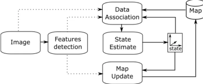
Features detection Data Association Map State Estimate Map Update Image state
Section 7 presents the final embedded prototype, discusses its validation through the experimental results obtained and compares it to state-of-the-art implementations. Section 8
presents our global conclusions and our future works.
2 State of the art and motivation
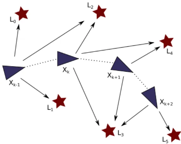
2.1 SLAM: general principleIn the framework of the autonomous navigation of a mobile robot or vehicle, the SLAM issue deals with the problem of incrementally building a map of an unknown environment explored by the vehicle, while simultaneously keeping track of the vehicle pose (position and orientation) in this envi-ronment (see Fig. 2). Various exteroceptive sensors have been used to sense the environment (e.g. ultrasonic sensors, laser range finders or one or several cameras). Tracking and matching landmarks over time allow updating the environ-ment map: the positions of already perceived landmarks are refined while newly perceived landmarks are integrated into the map, see [14]. Proprioceptive sensors (e.g. odometry or inertial measurement units—IMU) provide an estimate of the robot pose, notably allowing reducing the complexity of the landmarks tracking process. Tasks involved in the SLAM process may be described as front-end perception tasks, and back-end pose estimation and map update tasks, see [7, 37].
2.2 SLAM: different approaches
The approaches found in the literature for the SLAM process may be classified mainly into filtering-based approaches, and approaches based on bundle adjustment optimization.
Historically, filtering-based SLAM approaches (based on the use of an extended Kalman filter—EKF) have been proposed first (see for example [31]) and have remained very popular since then. Filtering-based approaches use probabilistic data to describe the robot state (robot pose) and the landmark positions in the environment map. Match-ing landmarks allows refinMatch-ing the map and the robot pose through a numerical process (the extended Kalman filter is widely used at this stage). EKF-based SLAM exhibits well-known limitations. First, the approach is complex, as EKF-based SLAM requires to integrate all landmarks positions and the robot pose in the same state vector and to manage their uncertainties (large covariance matrix) in the filtering process. The EKF-SLAM complexity is evaluated in Sola [40] to o(k⋅n2) , where n is the global number of landmarks
in the environment map and k is the number of landmarks observed at each algorithm iteration. Second, consistency problems appear, due to errors related to the linearization performed in the neighborhood of the system state, and to possible wrong landmark matches. Thus, the community
has explored other solutions. In Montemerlo et al. [29], the authors propose the FastSLAM algorithm, based on the use of a particle filter instead of the EKF. On the one hand, this approach reduces complexity by decorrelating the robot pose from the landmarks positions, but on the other hand, this approach also exhibits similar complexity and consistency issues (especially as the number of particles grows with the size of the environment map).
Another approach has been getting more and more inter-esting over the last few years: bundle adjustment SLAM per-forms optimization over selected key frames in the sequence of images acquired by the robot, see [30, 42]; incoming key frames correspond (for example) to images for which too few features matches are obtained, and the uncertainty of the robot pose is too high; key frames should be spatially distributed, and may be kept in limited number using a tem-porally sliding window.
In Strasdat et al. [42], the authors compare filtering-based and bundle adjustment-filtering-based SLAM approaches for purely software implementations, and conclude that key frame-based optimisation provide the best accuracy per unit of computing time if powerful processing units and large amounts of interest points can be used. But, the authors show that filtering-based approaches still appear beneficial for small processing budgets (as is the case in our study).
2.3 SLAM: extended Kalman filter
Filtering is the process of estimating the system state from noisy, partial and/or indirect state measurements.
The Kalman filter provides an optimal state estimate in the event of noisy measurements, assuming a Gaussian dis-tributed noise and a linear process model. The filter relies on the recursive estimation of the state and the stochastic
Fig. 2 Principles of the simultaneous localization and mapping
prob-lem: a mobile object (blue triangle) computes its local state Xk using
static information in the world frame (landmarks Ln ) and previous
properties of the process. Starting from an initial state and a stochastic model of the process and data sources, the fil-ter predicts the future state of the system together with its prediction error. The predicted state is then compared to the actual state observed from the measurements, to update the stochastic model and refine the state estimate. The updated stochastic model will help achieve better state prediction for the next iterations of the process.
The state prediction step is formulated as follows:
where ̂𝐱+ the predicted state, ̂𝐱 the current state , 𝐅 the state
transition matrix, 𝐏 the state error covariance matrix, 𝐏+ the
a posteriori error covariance matrix, and 𝐐 the covariance of the process noise.
The state update step is formulated as follows:
where H is the observation model matrix, Z is the innovation (difference between the observation and the predicted state) covariance matrix, 𝐊 is the Kalman gain matrix that allows updating the state and state error covariance matrix.
The extended Kalman filter extends this framework to the case of a non-linear process model. In the state prediction and state update steps, the observation and prediction func-tions are linearized around the current state of the system. An extended Kalman filter iteration for the visual SLAM problem can be formulated as follows:
1. The state is predicted using a movement model of the system that can integrate proprioceptive data (IMU, odometry… ), or a simpler model like a constant speed model.
2. The state observation step consists in observing map elements (landmarks) as features to be observed in the images. These observations are iteratively integrated into the filter following the update process step. 3. Features are detected in the image and integrated as
landmarks in the process state. These map points will later be used for the state observation step of the filter. This process implies, on the computer-vision side, the abil-ity to:
1. detect image features
2. describe image features in the world frame ̂𝐱+ =𝐅̂𝐱 𝐏+ =𝐅𝐏𝐅T+𝐆𝐐𝐆T, (1) 𝐙 = 𝐇𝐏𝐇T+𝐑, (2) 𝐊 = 𝐏𝐇T⋅ 𝐙−1, (3) ̂𝐱+ =̂𝐱 + 𝐊(𝐲 − 𝐇 ̂𝐱), (4) ̂𝐏+ =̂𝐏 − 𝐊𝐙𝐊T,
3. accurately match image features in a frame sequence These tasks must be performed with as much accuracy as possible since wrong image features or bad matches may endanger the filter stability.
2.4 Operational vision‑based embedded SLAM implementations
There are still very few real-time embedded operational full SLAM processing chains in the literature. Early works have proposed systems based on the use of telemeters or infrared (IR) sensors. For example, Abrate et al. [1] have proposed a solution involving eight low-cost IR sensors. The SLAM processing chain was implemented on a low-cost CPU Motorola 68331 processor. The processing times obtained limited the robot speed to 0.6 m/s. The emergence of low-cost cameras and the improvements of embedded processors performances have allowed the implementation of embedded vision-based SLAM solutions in the last few years. Bonato et al. [5] have proposed a system based on the use of four cameras (resolution: 320 × 240 pixels). The authors have implemented a SIFT interest points descriptor on a Stratix®
II FPGA. The hardware blocks are coded in Handel-C and the communication interfaces and cameras interfaces are coded in VHDL. The authors foresee performances for a complete vision-based 2D EKF-SLAM chain of 14 Hz with a consumption of 1.3 W. Nikolic et al. [32] propose the implementation of an embedded 3D vision-based (2 cameras) SLAM based on bundle adjustment on a hetero-geneous Zynq FPGA (hardware + software); the camera’s resolution is 752 × 480 pixels; the system proposed a hard-ware implementation of the extraction of FAST and Harris interest points (see [21, 36]), while the rest of the SLAM processing chain is not implemented on the FPGA. The sys-tem runs at 20 Hz. Faessler et al. [15] propose the imple-mentation of a 3D optimization-based monocular-dense SLAM on-board a quadrocopter. The camera resolution is 752 × 480 pixels, interest points used are FAST corners; the visual odometry chain is implemented on a CPU ARM®
(four cores, 1.9 GHz); dense map reconstruction is imple-mented on a ground segment (on a CPU i7 2.8GHz). The Wi-Fi communication between the on-board payload and the ground segment limits performances to between 5 and 50 fps (frames per second). In Vincke et al. [46], the authors propose a pure software implementation of a monocular 3D EKF-SLAM processing chain on a multiprocessor hetero-geneous architecture - OMAP3530 single chip integrating a RISC processor (ARM® Cortex A8 500 MHz) with a SIMD
Neon coprocessor, and a DSP (TMS320C64x+, 430 MHz) -. Again, the resolution of the cameras is limited to QVGA (320 × 240 pixels). The mean processing times performances announced are around 60 fps.
Considering our scientific and applicative context, these implementations all exhibit part or all of the following draw-backs: limited camera resolution, purely software implemen-tation, 2D (not 3D) SLAM, performances not compatible with ADAS, or involvement of optimization-based SLAM, while our objective is the implementation of a 3D EKF-based SLAM on a heterogeneous architecture, with perfor-mances compatible with ADAS constraints. To the best of our knowledge, there exists no implementation of a complete monocular 3D EKF-SLAM processing chain coping with the constraints of an ADAS.
2.5 Operational vision‑based EKF‑SLAM implementations at LAAS
Over the last few years, two operational vision-based EKF-based SLAM processing chains have been developed at the LAAS-CNRS laboratory.
Davison et al. [12] and Roussillon et al. [37] imple-ment a 3D EKF-SLAM processing chain called RT-SLAM (standing for real-time SLAM). Sensors used are an IMU and a single camera (VGA resolution, 640 × 480). It is a pure software implementation (in C++ language) running on an Intel Core i7 × 86 desktop processor. The number of landmarks in the environment map and the number of land-marks updated at each image acquisition are configurable. An active search strategy associated with a Harris features detector [21] allows observing, tracking and matching cor-ners. Newly observed landmarks are initialized in the envi-ronment map using a classical one-point RANSAC (random sample consensus) algorithm [11]. The global processing time performances reach 60 Hz, but consumption is too high for the ADAS context (140 W).
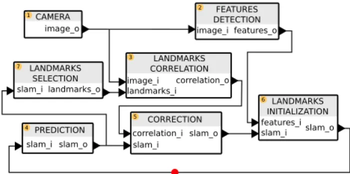
More recently, C-SLAM, based on RT-SLAM and pre-sented in Gonzalez et al. [20] was developed in C language; this software implementation did not use any external soft-ware library anymore (as opposed to RT-SLAM). In Botero et al. [6], the authors implement C-SLAM on a dual FPGA platform including a Virtex5 and a Virtex6 FPGAs. Perfor-mances reach 24 Hz (with 640 × 480 image resolution) while observing up to 20 landmarks in each acquired image (up to 20 × 24 landmarks updates/s). The C-SLAM implementation allowed to validate the software architecture presented in Sect. 3. The first three layers are in charge of the scheduling of the vision-based EKF-SLAM steps, while the low-level layer involves the computationally intensive operations (the latter layer is where the performance improvement oppor-tunities should be sought for). We have used this functional architecture as a starting point for the works presented here; the initial behavioral model used in our co-design approach (see Sect. 4.2) has been directly derived from this architec-ture (Fig. 3).
2.6 HW/SW co‑design methodologies
In the literature, many works related to the development of suitable methodologies for the prototyping of an embedded system can be found. A subset of these refers to heteroge-neous architectures and they can be classified [38] as: (A) top-down approaches, where the target architecture is gradu-ally generated from the behavioral system specification by adding implementation details into the design; (B) platform-based approaches, where a predefined system architecture is used to map the system behavior; and (C) bottom-up approaches, where a designer assembles the final hardware architecture by inserting wrappers between operational het-erogeneous components.
These methodologies can be referred to as co-design methodologies [mainly for approaches (A) and (B)] or design space exploration (DSE) [for approaches (A), (B) and (C)]. In the following, we explore existing methodologies for co-design; most methodologies in the literature are top-down approaches, that use an application model to specify the application behavior and structure (and thus constitute model-driven methodologies).
The model-driven design flow for the design space explo-ration (DSE) is a long-studied problem and has proved worthy in a number of applicative domains where the com-plexity of the targeted application and of the computing architecture may lead to a difficult design process.
In Bezati et al. [3] and Pelcat et al. [34], top-down approaches use the data-flow model of the application to ease the parallelism exploration to target heterogeneous multi-core architectures. Other authors use a high-level pro-gramming language that implements a data-flow model of computation that is to be automatically transformed into a valid hardware implementation or multi-core software, see [41, 49]. Some works rely on the UML model with its archi-tecture specific extensions (MARTE, UML 2.0 see [25]… )
to study an application and its supporting architecture in the same framework.
Other top-down approaches such as [23] or [9] only define the high-level methodology to be applied for DSE but leave the choice of the languages and the tools to the designer. Methodologies such as the one proposed in Calvez et al. [9] (see Sect. 4) guide the user from the input high-level specification to a valid system on a chip by imposing a number of intermediate steps (each step being associated with its local model and tests) that follow a V-chart flow. Methodologies such as the one proposed in Kienhuis et al. [23] only define a very coarse design flow from the applica-tion and architecture models to a mapping that meets the application constraints. An iteration of the flow maps the application model onto the architecture model and evaluates the performance of the mapping in a simulated environment. The architecture model is then refined until the application constraints are met.
All these methods and tools target the same goal: defining an optimal architecture (with respect to input constraints and input models) for a specific application through the design space exploration. Every method has domain-specific attrib-utes and constraints that may not fit our needs. In Sect. 3, we will propose a generic design flow, refined from Shaout et al. [38], and how we used it to guide our application development.
2.7 Synthesis: working hypothesis, scientific approach and contributions
In this paper, we aim at defining and validating a hetero-geneous hardware/software architecture for the integration of a complete monocular vision-based 3D EKF-SLAM processing chain meeting the constraints of an ADAS. In Strasdat et al. [42], the authors show that filtering-based approaches appear beneficial for small processing pro-cess budgets, as is the case in our study (integration of
a monocular sparse vision-based SLAM chain, where a limited number of interest points will be tracked). Further-more, with optimisation-based approaches, latency cannot be guaranteed, while the number of operations involved in one EKF state update step is deterministic for a given state vector dimension.
Our SLAM-related working hypothesis (derived from the RT-SLAM, see [37], and C-SLAM, see [20]) is as follows:
• we use an IMU system for vehicle motion estimation in the SLAM prediction step;
• we use a single camera (resolution: 640 × 480 pixels) for exteroceptive perception;
• we initialize up to five new landmarks in the map for each acquired image;
• we integrate up to 20 landmarks observation in the SLAM correction step;
• we use a corner detector to extract sparse interest points; the process involves a tessellation of the acquired images to provide a better distribution of the extracted interest points in each image;
• the tesselation grid uses 40 × 40 pixels tiles resulting in a 16 × 12 grid (see Sect. 6.1).
Efficient embedded systems must provide high computa-tional performances and low consumption [19]. The appli-cative ADAS-related context and the cooperative DICTA project (see Sect. 1) have helped to define the performance target constraints on our system. Frequency requirements are set to a minimum of 30 Hz (or frames per second). The constraints on the latency of the complete processing chain are set to at most 1 image. We also aim at keeping the total system consumption lower than 5 W and the design footprint as small as possible (within 25 cm2×2 cm ) since we should be able to embed the final SLAM implementation on-board an iCam smart camera, see [13]. None of the operational vision-based SLAM implementations presented in Sects. 2.4
and 2.5 meets these constraints.
The choice of the target platform is linked to the choice of the associated processors. CPUs and GPUs (and to a lesser extent DSPs) provide a much easier imple-mentation of complex algorithms than FPGAs (based on reprogrammable logics and leading to much higher implementation complexity and time). But FPGAs gen-erally lead to far better real-time processing (namely latency and throughput) and power consumption perfor-mances, see [17, 35]. When tackling the implementation of embedded complex algorithms (here, dealing with advanced image processing), heterogeneous hardware/ software architectures combining a CPU and a FPGA may allow efficient trade-offs; the algorithms of higher complexity, processing low volumes of data or called at low frequencies may be implemented on the CPU;
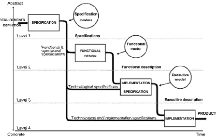
Level 1 Level 2 Level 3 Level 4 Abstract Concrete PRODUCT Time SPECIFICATION FUNCTIONAL DESIGN IMPLEMENTATION SPECIFICATION Specifications Functional description Executive description Specification Functional Executive Technological specifications
Technological and implementation specifications Functional & operational specifications models model model IMPLEMENTATION REQUIREMENTS DEFINITION
algorithms which are more systematic and/or process high data volumes (typically here, low-level image pro-cessing algorithms applied to large number of pixels) can be efficiently and massively parallelized on a FPGA. We chose to implement our embedded SLAM chain on a Zynq-7020 FPGA, only Xilinx® heterogeneous
plat-form providing a heterogeneous architecture combining a CPU (ARM® dual-core Cortex A9 processor) and a
FPGA, at the start of the works described here. We chose Avnet’s ZedBoard environment for the prototyping of our 3D EKF visual SLAM SoC; this low-cost platform pro-vides all interfaces functionalities for a PC, a monitor, and a USB camera, and relevant processing and memory resources. In particular, it provides an energy-efficient multi-core ARMv7 processor (667 MHz), a Zynq-7020 FPGA device, 512MB DDR3 RAM and a Xillinux [47] distribution which comes quite handy for our needs as it allows memory-mapped and streaming interfaces between the logic fabric and the host processor(s) at no additional engineering effort.
In the following, we describe our implementation of a complete monocular 3D EKF-SLAM on a heterogeneous architecture. Our contribution is threefold:
• we have selected in the literature a (standard and generic) co-design approach which we have (1) refined to allow the integration of a complex processing chain such as a vision-based monocular SLAM and (2) adapted to encompass a hardware-in-the-loop approach allowing to integrate hardware accelerators of advanced image pro-cessing or algebraic data propro-cessing functions involved in the filtering process. In our approach, the hardware accel-erators are integrated one by one. The HIL progressive integration of hardware accelerators is made by using a systematic rule on the results of the cost (here, latency and throughput) profiling of the hardware and software functional components of the heterogeneous SLAM chain under construction.
• we have used this refined co-design method to integrate the first complete monocular extended Kalman filter (EKF) SLAM chain on a heterogeneous (hardware/soft-ware) architecture on a single SoC. The obtained process-ing chain performances meet the constraints of the pro-cessing times, power consumption and design footprint of the ADAS.
• we have designed several original hardware accelera-tors reusable for any embedded SLAM application or vision application involving the same functions. Indeed, we have proposed and validated original hard-ware accelerators of all the image processing function-alities involved (extraction of interest points corners and computation of their descriptors, tessellation of the images for a better distribution of the interest points
all over the images, matching and tracking of the inter-est points over the sequence of images). We also have developed and validated an original hardware accelera-tor for the multiplication of matrices involved in the EKF filtering steps.
3 Proposed co‑design methodology
Co-design is a well-covered scientific topic with solutions ranging from pure design methods to semi-automated design flows. We have identified the following flaws in the existing aforementioned methods (see Sect. 2.6):
• ASIC/SoC oriented design flows do not specify optimi-zations at the application model level but rather tend to optimize at the implementation level.
• co-design workflows such as in Calvez et al. [9] tend to prefer local iterations at each step (e.g. specification, design, implementation) rather than global iterations (see Fig. 4).
• in design flows such as the one proposed in Pelcat et al. [34], the scheduling partitioning can completely be rede-fined between two iterations of the same flow with differ-ent constraints/scenario input
• design flows such as [34] tend to consider that the designer has an extensive knowledge of the application constraints/properties before prototyping. The flow does not specify how the designer improves the knowledge along the design iterations.
• fully automated design flows (see for example [41, 49]) somehow fail to capture the full extent of the designer’s knowledge.
In an effort to get a design flow that simultaneously:
• captures the designer knowledge,
• ensures limited partitioning modifications between two consecutive iterations of the design flow,
• allows for the integration of model-level optimizations,
• ensures IP/software capitalization,
• and allows for HIL performance evaluation,
we came up with the generic workflow depicted in Fig. 5. This design flow aims at guiding the designer through the DSE but does not include any automatic steps nor is supported by any software tool.
The following subsections describe the workflow steps and then introduce its application to the implementation of our vision-based EKF-SLAM chain.
3.1 Design flow description
The design flow starts with an initial model of the applica-tion and either a single-core initial architecture or an archi-tecture imposed by the application. The initial constraints capture the affinity for tasks to be executed on a given processing element and the costs associated with each task (evaluation of task processing time, power consump-tion, memory footprint … ). In a first iteraconsump-tion, the model is scheduled over the given architecture to evaluate the initial
latency (only performance cost that can be evaluated at this step of the co-design method) of the application. This result allows the user to refine the architecture model (i.e., add parallelism degrees) and the application model (i.e., expose more potential parallelism) iteratively, over steps 1 and 2. Once the architecture and application model is considered valid regarding the target latency, the designer can move forward through the prototyping process.
The next step (synthesis) aims at building a software-only functional prototype of the application. The designer validates each of the software components using unit-testing techniques. Each of the validated blocks then contributes to a software libraries catalog, to be used for the initial proto-type. This initial prototype implements the schedule defined earlier together with the communication primitives for inter-process communication.
This initial software prototype is evaluated against the actual performance defined in the constraints: it is profiled to evaluate the component costs. If the target performance is not met, the actor with the highest cost is selected for optimization. The design flow thus loops back to the Hw/ Sw partitioning with the affinity of the selected actor set to hardware in the constraints. Once an actor is implemented in hardware, the current stage prototype performance is evalu-ated using an HIL approach. The hardware accelerators are integrated one at a time: a single accelerator is integrated at each global iteration of the HIL process. This design loop keeps going until the prototype meets the target cost.
Similarly to state-of-the-art co-design methods, the pro-posed design workflow guides the platform designer from model-based specification to a prototype that meets the application constraints. It goes through a number of proto-typing steps with local iterations to achieve locally required performance.
The main contributions of this workflow are that: 1. optimizations are performed at the model level and at
the implementation level, whereas some methods only consider the model level in the design flow;
2. a systematic decision rule is used to improve the applica-tion’s partitioning;
3. knowledge is improved at each iteration through profiling; 4. partitioning is modified one task at a time;
5. implementation costs can relate to different attributes (throughput, latency, power consumption) to cover dif-ferent application domains.
3.2 Design flow applied to our vision‑based EKF‑SLAM application
In the following, we describe the design iterations we followed to conduct the development or our embedded
real-time vision-based EKF-SLAM implementation. Sec-tion 4 describes the modelling of the design flow inputs. In Sect. 5.1, we detail the optimizations at the application model level for the platform specification step. Then we will successively integrate hardware accelerators (vision-related processes and algebraic operator) to meet the targetted costs (see Sect. 6) as depicted in Fig. 6. The evaluated costs in our application will be the throughput to meet our target frame rate, the design footprint and the power consumption of the system (see Sect. 4.3).
4 Architecture, application and constraints
modelling
This section deals with the application of step 1 of our co-design methodology, named “Modelling”. This stage estab-lishes the architecture model (see Sect 4.1), the application model (see Sect. 4.2), and the constraints on the system (see Sect. 4.3).
4.1 Architecture model
As explained in Sect. 2.7, we target an architecture with general purpose processing capabilities and room to inte-grate hardware accelerators. We chose the Zedboard®
development platform based on the ZynQ® Soc that
fea-tures the following attributes:
• an energy-efficient dual-core ARM® v7 processor
(667MHz);
• 512 MB DDR3 RAM;
• 80k logic cells, with DSP and memory blocks;
• a Xillinux [47] Linux distribution which comes quite handy for our needs as it allows memory-mapped and streaming interfaces between the FPGA and the host processor(s) at no additional engineering effort. This development platform does not meet our physical footprint constraint of 25 cm2×2 cm , but our design has
the potential to be shrinked to this size. While the on-board SoC can have a larger power consumption than the target (5 W), we will optimize the logic and software to meet that limit.
Our architecture model is composed of two CPU with available logic to host our custom hardware accelerators.
4.2 EKF‑SLAM application model
The visual EKF-SLAM chain can be described by the following pseudo-code, that we formerly used for our C-SLAM implementation, see [20]:
1: slam = init slam(map size) 2: for n = 0; ; n + + do 3: image = acquire f rame()
4: predict(slam, robot model);
5: j = 0;
6: lmk list = select lmks(slam);
7: correl list = correl lmks(lmk list, f rame);
8: for i = 0; i < size(correl list) and j < nb correct; i+ + do
9: if score(correl list[i]) > correl threshold then 10: correct slam(correl list[i]);
11: j + +;
12: end if
13: end for
14: f eature list = detect f eatures(f rame);
15: j = 0;
16: for i = 0; i < size(feature list) and j < nb init; i++ do
17: if init lmk(feature list[i]) then 18: j + +;
19: end if
20: end for 21: end for
where:
• slam is the global structure that holds the SLAM state and additional information;
• lmk_list is a list of landmarks selected in the environ-ment map for tracking;
• correl_list is the list of observations of these selected landmarks in the current image;
• feature_list is the list of newly detected interest points in the current image;
Fig. 6 Iterations for our co-design flow applied to our hardware
pro-totype; each red arrow represents the accelerators successively inte-grated in our HIL approach
and:
• slam_init() is a function that initializes the SLAM state given a map size;
• predict() is a function that performs the prediction step of the EKF filter;
• select_lmks() is a function that returns a list of land-marks to be observed in the current image;
• correl_lmks() is a function that observes (matches) the selected landmarks with interest points in the current image;
• correct_slam() is a function that performs the correction step of the EKF filter;
• detect_features() is a function that detects interest points in the image;
• init_lmk() is a function that initializes landmarks cor-responding to newly detected interest points (landmark initialization). The function returns 0 if the environ-ment landmark map is full.
This pseudo-code can be configured with the following parameters:
• correl_threshold , the minimum correlation score for a landmark to be integrated to the correction step;
• map_size , that defines the total number of landmarks to be managed in the environment map;
• nb_correct , that defines the number of EKF correction to be executed per frame;
• nb_init , that defines the maximum of new landmarks to be integrated into the environment landmarks map per frame.
In our C-SLAM implementation, those parameters take the following values:
• nb_correct = 6,
• nb_init = 5.
This C-SLAM algorithm is then adapted to run in an SDF (deterministic) manner. We obtain the SDF model pre-sented in Fig. 7.
4.3 Constraints
We remind here briefly the targeted performance contraints expressed in Sect. 2.7:
• SLAM throughput: 30Hz (30 fps);
• SLAM latency: 1 image;
• power consumption: 5 W;
• small physical footprint (within 25 cm2×2 cm).
Now that all the required design flow inputs are defined, we can start iterating the design flow, starting with the model level optimization.
5 Iteration 1: initial platform specification
and model refinement
As we explain in this section, the initial model does not expose a lot of parallelism and we are not satisfied with the initial latency evaluation; thus we decide to optimize the schedule latency at the model level (see Sect. 5.1). Then, we present the software-only obtained prototype assessment (see Sect. 5.2).
5.1 Application model refinement
In SDF applications models, more parallelism can be exposed at the structural level by applying re-timing tech-niques. Re-timing consists of adding delay tokens on the graph edges to modify the application pipeline.
Such modifications do not affect the structural aspect of the model (the way that nodes are connected) and the schedule length, since the repetition vector of the graph is preserved, but the latency of schedule can be positively affected.
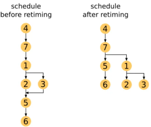
In our 3D EKF-SLAM application, re-timing was achieved by delaying the prediction, correction and landmarks initialization tasks (starting from the SDF model presented Fig. 7, these tasks are delayed in Fig. 8).
Before this re-timing, the directed acyclic graph (DAG) of the application is defined as shown in Fig. 9 (on the left of the picture), with only Feature_detection (2) and Land-marks_correlation (3) to be executed in parallel and a paral-lelism level of 1.16 ( paralparal-lelism = T1∕T∞ with T1 =7 and
T∞=6).
After re-timing, the DAG of the application is defined as shown in Fig. 9 (on the right of the picture), where the filtering [Correction (5)] and [Landmark_initialization (6)] tasks are allowed to be executed in parallel of the vision
tasks. Parallelism level is now 1.75 ( Parallelism = T1∕T∞
with T1=7 and T∞=4).
The application now exposes three-degree parallelism. This allows creating a clear partitioning between the filter-ing tasks (landmarks selection, prediction, correction, land-marks initialization) and the vision tasks (feature detection, landmarks correlation). Re-timing may affect the SLAM’s performance since the behavior of the tasks must take the re-timing into account, but is necessary to meet the execu-tion time constraints on a heterogeneous architecture. In this case, the designer should take into account the behavior of the landmarks correlation task as its function is to find land-mark matches between the past and the current frame. In cases of, e.g., sudden changes in the orientation, it is highly likely that we ”lose” a large number of landmarks. Given the fact that the correction task operates on landmarks from the precedent frame, the quality of the prediction may be cor-rupted in case of a low number of (or no) landmark matches. Thus, a larger number of landmarks needs to be correlated.
In conclusion to this subsection, we generalize our opti-mized model as a filtering-based visual SLAM application that stands:
• whatever the filtering technique involved in the correc-tion task is
• whatever the feature detection and correlation techniques involved in the features detection and landmarks correlation tasks are
in a filtering-based visual SLAM application.
5.2 SW‑only prototype
After the model-level optimization, the model is mapped onto the ZynQ® dual-core architecture with all actors
affini-ties set to software. The prototype consists of two threads T1
and T2 with appropriate synchronization and communication
happening through software FIFOs (see Fig. 10).
Vision and filtering tasks are being allocated (mapped) onto two different threads. At this stage, there is no task mapped on a reconfigurable hardware device (FPGA); the entire application is running on the host processor.
This software-only prototype does not match our target throughput (see Table 5). The actor with highest computing cost is identified as the features detection and its affinity is set to hardware in the application constraints.
6 Iterations 2–4: hardware accelerators
This section presents the hardware accelerators developed along the iterations of our HIL-oriented co-design methodol-ogy (see Fig. 24). We remind that in our co-design method-ology, hardware accelerators are integrated one at a time (a single accelerator is integrated at each global iteration of the HIL process). The choices of the successive functionalities to be accelerated are made using the following systematic rule: the costliest function (as far as computing cost is con-cerned) is the next to be implemented on hardware. The main iterations will be summarized at the end of the co-design process (see Fig. 24).
Our main contributions here are the following FPGA-based original hardware accelerators:
• an accelerator for the features detection task (front end— see Sect. 2.1—vision task accelerator including the hard-ware implementation of the FAST interest points associ-ated with an image tesselation process), implemented in iteration 2 and presented in Sect. 6.1;
Fig. 8 Re-timed application SDF model
Fig. 9 Application DAG before and after re-timing
• an accelerator for the correction step of our EKF-SLAM (back end—see Sect. 2.1—filtering task accel-erator), developed during iteration 3 and presented in Sect. 6.2;
• an accelerator for the correlation task (front-end vision task accelerator) of our EKF-SLAM, developed during iteration 4 and presented in Sect. 6.3.
6.1 Iteration 2: feature detection hw accelerator
Image features detection is the task of detecting, in images, interesting image structure that could arise from a corresponding interesting scene structure, e.g., a landmark in the scene. Image features can be interest points, curve vertices, edges, lines, curves, surfaces, etc., (see [16]). Our vision-based EKF-SLAM implementation relies on the detection and tracking of corners in an image sequence. The corner detection methods presented in Harris and Stephens [21] and Shi et al. [39] analyze the gradient in the local neighborhood of the potential corner in the pro-cessed image through a structure tensor. In Bay et al. [2] and Lowe [28], a difference of Gaussian (DoG) is used to detect a corner. Some of these corner detection methods were successfully implemented on FPGA (see [4, 48]), but the resource count (memory and logic blocks) can be fairly high . FAST (feature for accelerated segment test, see [36]) is a corner extraction method with good corner extraction performances and a very low software com-plexity. This method is also well suitable for hardware implementation with a very low resource count and no use of DSP blocks, see [24].
There are very few implementations of feature detec-tion modules on a dedicated hardware architecture in the literature. Birem and Berry [4] have implemented a Har-ris point detector on an Altera® Stratix I® target. But the
Harris detector is implemented on (many) DSP blocks of the component. Nikolic et al. [32] have proposed an implementation of Harris and FAST points detectors on a Xilinx® Spartan 6®. A pixel is processed over four system
clock ticks, which limit the input pixel stream frequency. Kraft et al. [24] have implemented a FAST point detector on a Xilinx® Spartan 3®. The feature detector is executed
at 130 Mpixels per second (corresponding to almost 500 frames per second for an image resolution of 512 × 512), which meets our ADAS-related constraints (as far as throughput is concerned).
In this subsection, we present the design and implemen-tation of our hardware accelerator for the FAST feature extraction, based on the implementation proposed by Kraft et al. [24] and optimized by us (see [7]) to achieve a better maximum frequency (thanks to a pipelined adder tree) and memory consumption (only one 36k BRAM used).
6.1.1 FAST corner detector
The FAST corner detection at a given candidate pixel of an image (called reference, current or central pixel here) relies on the analysis of the local gradient between this reference pixel and the pixels located on a Bresenham circle centered on the reference pixel (Fig. 11). Let Pi ( i ∈ [0, BCs−1] ) be the pixels located on this circle, where BCs is the size of the Bresenham circle (i.e., the number of pixels on the circle). Pixels located on the circle are classified into two classes (darker or brighter) according to the following conditions :
where p is the reference pixel, t is a threshold, Ip is the inten-sity of the reference pixel and IPi is the intensity of a given
pixel on the Bresenham circle. If a set of minimum N con-tiguous pixels are classified as brighter or darker, then p is classified as a corner. The detector has got three parameters: the Bresenham circle size BCs , the threshold t and the mini-mum number of contiguous pixels N.
Figure 11 shows an example of a corner with the corre-sponding Bresenham circle.
Once a corner is detected, its score, given by Eq. 5, is computed.
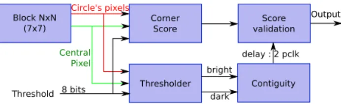
Figure 12 presents the global architecture of our hardware accelerator for the FAST feature detection. The FAST hard-ware implementation is composed of four processing blocks: Thresholder, Corner Score , Contiguity and Score Validation.
The Thresholder processing block uses threshold t to compare the central pixel to the pixels on the circle, and provides two vectors of BCs bits each indicating whether the successive pixels on the circle are, respec-tively, brighter or darker than the central pixel. These two ClassPi= { darker IP i ≤ (Ip −t) brighter (Ip+t) ≤ IP i, (5) V =max ( ∑ Pi∈brighter |IPi −Ip| − t, ∑ Pi∈darker |Ip−I Pi.| − t )
Fig. 11 Fast corner detection principle on sample image used in a
vectors are used by the CornerScore block, that computes the current pixel score V. The Contiguity block determines whether at least N contiguous pixels are brighter or darker than the central pixel. There are BCs−N successive arcs of N contiguous pixels on our Bresenham circle; for each of these arcs, N comparisons are needed to check whether all pixels belong to the same (brighter or darker) class. Therefore, our Contiguity block uses BCs−N comparators, each of them performing N comparisons. All comparisons are performed in parallel. If at least one of the contiguity tests performed by the BCs − N comparators is successful, the presence of a corner and its score are validated by the Score validation block.
The implementation of the four material processing blocks is composed of logic elements performing sums, dif-ferences, absolute values and comparisons. The implemen-tation of most of these is quite straightforward. The inputs of the CornerScore and Thresholder processing blocks are the central (current) pixel, the pixels of the Bresenham cir-cle, and threshold t. Outputs of the Thresholder processing block (and inputs of the Contiguity block) are the elements of the BCs bits vectors indicating whether the successive pixels on the circle are, respectively, brighter or darker than the central pixel. The main hardware acceleration is provided by the adder tree instantiation which computes pipelined additions. It allows to perform, in our case, addi-tions of eight inputs per clock cycle—with a latency two clock cycles instead of eight clock cycles using a basic processor, see [7].
As far as the pixel pipeline flow is concerned, pixels are stored in a cache (BRAM) allowing to feed the FAST corner detection hardware blocks with the pixels on the Bresenham circle . If BCd is the diameter of the Bresenham circle, we need a sliding processing region of BCd×BCd pixels in the image; thus, we need to buffer BCd image lines.
Our hardware architecture is generic. The size of the Bresenham circle BCs , the threshold t and the number N of contiguous pixels needed to detect a corner can be param-eterized. The typical values we have chosen are BCs=16 , N =9 and t = 20 , recommended by Rosten and Drummond [36].
The results of our material architecture implemented for the detection of FAST features are consistent with the state-of-the-art functional implementations (we assessed this
through a comparison with a software implementation based on the use of the OpenCV library).
On our FPGA target (Xilinx® ZynQ® zc7z20), we obtain
a maximum frequency of 160 MHz, i.e., our feature detec-tion hardware accelerator can process up to 160 Mpixels/s (maximum frequency for a VGA image resolution) with a latency of BCd pixels and BCd image lines (7 lines for a Bresenham circle of 16 pixels perimeter). This throughput corresponds to the processing of up to 77 frames/second for a full HD image resolution ( 1920 × 1080 pixels), with a maximum power consumption of 2.5 W (estimated using the Xilinx® XPower Analyzer® tool). These results bring to
light a very good computational power/consumption ratio and validate our FAST interest point extraction hardware accelerator. Table 1 summarizes the use of the resources of the FPGA.
In comparison with the state of the art of FAST feature extraction hardware accelerators, the architecture proposed in [24] uses 12 BRAMs, 2368 LUTs and 1547 registers of a Spartan® 3 FPGA, with a maximum processing clock
of 130MHz (for a 512 × 512 images). The improvements brought by our architecture are a lower BRAM count and the use of a pipelined adder tree to increase the maximum frequency.
6.1.2 Tesselation hw accelerator
The second hardware acceleration of the feature detection front-end vision task is the tesselation of the corner extrac-tion. Tesselation is the process of tiling the image in small blocks using a rectangular grid having Rows lines and Cols columns, to beneficially:
• reduce the image processing complexity by applying image processing techniques only to a subset of image blocks (delimited by the grid cells) instead of processing the entire image;
• avoid the need for the use of a non-maxima suppres-sion technique since we extract a single feature (the one with maximum score) within each tesselation grid cell. In our original software-only SLAM implementation, this tesselation was used so that at each iteration only five image blocks were selected to compute the corner
Fig. 12 FAST architecture
Table 1 Use of the logic resources of the Zynq xc7z20-1clg484 for
VGA ( 640 × 480 ) image resolution
Logic utilization Used Available Utilization (%)
Slice LUTs 5963 53200 11
BRAM (18 k/36 K) 0/1 140 (38 K) 0.5
detection (see parameters settings presented in Sect. 4.2) and only one corner per image tile was extracted. This helped reduce the image processing time but also allowed the algorithm to improve the spatial distribution for the corners to be integrated as landmarks into the SLAM map.
Our tesselation module uses a BRAM memory that stores the best score for each tile. Since the image is pro-cessed as a stream of pixels, only a single tile is active (i.e., currently being searched) at a time. The score and maximum position for a given block are output when the pixel stream reaches the bottom right corner of the block. The module outputs a stream of scores and corresponding maxima positions (one maximum position and correspond-ing score per block).
The memory consumption (Mem) of the FAST feature extraction and tesselation hardware modules depends on the number of columns (Cols) of the tesselation grid, the number of bits used to code the (X, Y) position of a pixel with maximum score in a block (nbrbitX and nbrbitY) and the number of bits used to code the score (nbrbitscore). The following Eq. 6 computes the memory consumption: In our case, Cols = 16, nbrbitY = 10bit, nbrbitX = 10bit and nbrbitscore = 12bit. The tesselation hardware module requires only Mem = 512 bits.
Our tesselation HW module also implements two coun-ters (a pixel counter and a line counter) which allow defin-ing the current tile (i.e., currently active tesselation grid cell) index and the current pixel position in this tile. A comparator compares the current pixel FAST score to the maximum score in the tile and stores the current score and position in the BRAM only if this score is higher than the current maximum score in the corresponding tesselation grid cell.
Figure 13 shows the tesselation grid, in black, and the highest score in each tile, in color: colors used range from red to blue for an increasingly good feature.
Our tesselation module efficiently helps meeting the pro-cessing times constraints for our embedded SLAM chain. Moreover, a feature is detected by the FAST corner detector only one time, during the feature initialization step. Then, by updating the EKF filter, the algorithm predicts the new fea-ture position in the next frame. Thus, the feafea-ture is tracked by correlating the descriptor BRIEF in a given and predicted area of research (see Sect. 6.3).
Furthermore, the latency of the FAST feature extrac-tion and tesselaextrac-tion hardware modules is fixed and given by Eq. 7:
where IMGH = 480 , Rows = 12 and FASTrad = 4 pix-els, where IMGH is the number of lines in our images
(6) Mem = Cols × (nbrbitY + nbrbitX + nbrbitscore).
(7) L = (IMGH∕Rows + (FASTrad))lines+1
pixel,
and Fastrad is the radius of our Bresenham circle. Latency = 44 × linelatency+1 × pixel
latency.
The processing pipeline of the FAST feature extraction and tesselation hardware modules also transfers back to the software processor a fixed amount D of data which depends on
Rows, Cols, nbrbitX, nbrbitY and nbrbitscore (the num-ber of bits used to code a corner score).
i.e., D = 768 Bytes in our design.
The new scheduling obtained after the integration of our feature detection and image tesselation HW accelerator is presented in Figs. 14, 15 and Table 5.
6.2 Iteration 3: algebraic hardware accelerator
The goal of this section is to give a theoretical background to identify the computational bottleneck of the EKF block used for a visual EKF-SLAM algorithm in general. After-wards, we will focus on the integration of an adequate EKF accelerator.
(8) D = (Cols×Rows) × (nbrbitY + nbrbitX + nbrbitscore),
Fig. 13 Tesselation on FAST corner detection result
Fig. 14 Schedule of the SLAM application after second iteration
The profiling of our accelerated EKF-SLAM implemen-tation shows that the most time-consuming task is
correc-tion_slam. According to our methodology, this task must
now be accelerated through the use of hardware IPs.
6.2.1 Complexity study of extended Kalman filter for the correction step
The EKF general framework was described in Sect. 2.3; the following Table 2 gives a breakdown of data sizes for the correction step (see Eq. 4), using:
• N, the number of landmarks observed in the correction step ( N = 20 in our implementation);
• r the size of the robot state vector ( r = 19 in our imple-mentation)
6.2.2 Vision‑based EKF accelerator co‑design
In Thrun et al. [44], the authors show that computational requirements for an EKF algorithm depend on the num-ber of features N retained in the map: LEKF=O(N2) . We
can see that the most computationally expensive equations take place in the correction loop while updating the cross-covariance matrix (see Eq. 4) which makes for 85% of all the floating-point operations (FLOPs) when N = 20 , which matches the profiling of our EKF-SLAM implementation. Thus, a significant speed-up can be obtained by leveraging the floating-point KZKT tri-matrix multiplication and sub-traction operations in hardware.
Another particularity of visual EKF-based SLAM is that the dimension of the covariance innovation matrix Z is always 2 × 2 . Moreover, in the literature, efficient recon-figurable designs harboring matrix multiplication opera-tions in floating-point precision are processing element
(PE) oriented, see [22, 50]. Consequently, we can rewrite P − KZ × Kt as a PE-based pseudo-code: Phase I: K × Z 1: for i= 0;i <7N+ 19;i+ +do 2: P Ein(i) ={Ki0, Ki1} 3: for j= 0;j <2;j+ +do 4: P Ein(i) ={Z0j, Z1j} 5: P Eout(i) =Ki0× Z0j+Ki1× Z1j 6: end for 7: end for Phase II: P − KZ × Kt 1: for i = 0; i < 7N + 19; i + + do 2: P Ein(i) = {KZi0, KZi1} 3: for j = 0; j < 7N + 19; j + + do 4: P Ein(i) = {Kt0j, Kt1j, Pij} 5: P Eout(i) = Pij−(KZi0×Kt0j+KZi1×Kt1j) 6: end for 7: end for
Phase I and Phase II are executed sequentially on the same PEs. Each PE consists of two floating-point multi-pliers, one floating-point adder (which perform KZKt ) and one floating-point subtractor (which performs P − KZKt ). Thanks to the size of the Z matrix, we are able to instanti-ate multiple PEs that do not have to communicinstanti-ate to each other intermediary multiplication values (on line 5 of both Phase I and Phase II pseudocodes the output function of a PE does not depend on intermediary multiplication values). This design permits subtractions in equation P − KZ × Kt to be executed right after the multiplication under the con-dition that each corresponding element of the P matrix is already fetched from memory. Thus, not only the tri-matrix
Table 2 EKF matrix description Symbol Dimension Description
̂x, ̂x+ (
7N + r) × 1 Robot and feature positions (actual and predicted)
P, P+ (7N + r) × (7N + r) Cross-covariance matrix (actual and predicted)
P1 r × r Cross-covariance matrix with respect to robot position P2 r × 7N Cross-covariance matrix with respect to all landmarks
P3 7 × 7 Cross-feature–robot covariance matrix
P4 (7N + r) × 7 Cross-feature–feature and robot–robot covariance matrix
Fx r × r Jacobian to system state
F
𝜔 r × 6 Jacobian to system state perturbation
Z 2 × 2 Covariance innovation
H 2 × 7 Jacobian
R 2 × 2 Measurement noise
K (7N + r) × 2 Filter gain
multiplication is executed in a pipelined manner, but we also improve the performances of the subtraction as its latency is now the one of a single floating-point subtractor. Results are output column-wise which eases later addressing issues in software, see Fig. 16.
As our entire EKF-SLAM algorithm is designed to run as a SoC on a ZynQ device, we designed and implemented a generic accelerator that takes into account both latency and the aforementioned integration issues. We instantiate four PEs. In terms of latency, performances are close to the theoretical speed-up, see [43]. The reasons for not having instantiated more PEs are tied to resource usage (LUTs for logic and DSP48E embedded multipliers for floating-point calculations), and thus the percentage of the used area on the device which would consequently decrease the maximum operating frequency and/or the power consumption.
Having in mind that square matrix P is the biggest struc-ture in our SLAM algorithm in terms of memory usage, it is imperative to ensure efficient data communication between the accelerator and the rest of the system. In Table 3, we can see the influence of N2 in equation P − KZ × Kt , as far as the number of element-wise memory accesses is concerned, by changing the value of N. An accelerator which would transfer back all the results into external memory (where program data are stored) would suffer from a large memory access penalty with growing N. By storing the P matrix in on-chip memory instead of storing it in external memory and by modifying the software to access the contents of P in on-chip memory, we would in addition gradually increase the efficiency of the accelerator.
In each EKF iteration, matrices P1 , P2 , P3 and P4 are
fetched and updated from on-chip memory via a dedicated
AXI bus. Then, matrices Z and K are copied from external memory to on-chip memory (iBRAM). Control data are communicated directly from the Xillinux user space to the co-processor. The logic fetches by itself matrices Z, K and P, and stores the result back in P (oBRAM) via dedicated XIL_BRAM buses. The processor is notified of the end of execution via an interrupt signal.
After the integration of this back-end accelerator, the 3D EKF SLAM’s tasks’ timing changes as on Fig. 17.
Since the accelerator IP is generic, our co-design tech-nique may be migrated to bigger reconfigurable devices if there is a demand for more processing power (PEs). Accel-erator was also successfully tested as a PLB peripheral for heterogeneous designs on a FPGA with IBM’s PowerPC440 embedded processor.
The resulting speed-up when using the algebraic accelera-tor is listed in iteration 3 of Table 5. This table shows that the next iteration of our design workflow must now target the acceleration of the landmark correlation step.
6.3 Iteration 4: feature correlation hw accelerator
In this section, we present an original hardware accelera-tor for the tracking and matching of features through the input image flow. Our working hypothesis is derived from our initial software C-SLAM implementation, see Sect. 2.7. The landmark map is initialized from the initially detected FAST features. Then, the selected features are tracked in the next images using an active search strategy [20]. The size of the search windows is derived from the innovation covariance of the EKF state. A descriptor-based matching in these searching areas is performed by comparing feature descriptors.
Many approaches to compute feature descriptors can be found in the literature. The Binary Robust Independ-ent ElemIndepend-ent Feature (BRIEF) descriptor [8] has got many advantages over the other well-known SIFT [28] or SURF [2] descriptors from the point of view of their suitability for hardware implementation. It is indeed a binary descriptor representing the distribution of gradients in the neighbor-hood of the pixel of interest. First, a Nb×Nb patch centered on this pixel is extracted. Mb pairs of pixels in the patch are randomly selected (see Fig. 18), and for each pair p0, p1 , a
bit is generated as follows:
Fig. 16 Generic tiling for P − KZ × Kt
Table 3 Transfer analysis regarding P matrix in EKF equations
%xfers on N = 6 N = 13 N = 20 FPFT+ GQGT 1.21 0.2 0.06 HPHT + R 3.95 1.4 0.7 PHTZ−1 17.2 11 7.96 P − KZKT 74.96 86.45 90.8
This results in a Mb-bit long binary descriptor. The BRIEF descriptor can be computed very fast, is very compact and exhibits good stability for the matching. The descriptor is robust to illumination changes and small rotations (less than 15◦ ) [8] which makes it a good choice for SLAM
applica-tions. Its simplicity makes it a good candidate for hardware implementation. The comparison of two binary numbers can be done very simply and implemented very efficiently.
For our embedded SLAM implementation, we associ-ate each FAST feature detected in the images to a BRIEF descriptor. We decided to compute 128-bit descriptors in a 9 pixels × 9 pixels neighborhood.
Comparing the BRIEF descriptors of 2 pixels comes down to computing the Hamming distance of two 128-bit vectors. Eqs. 9 and 10 show the two steps of the Hamming distance computation:
where nOnes() counts the number of bits equal to ’1’ in the tmp vector. Counting the ones in a 128-bit vector proves expensive in term of hardware and latency. To simplify the process, the input 128-bit vector is divided into smaller vec-tors of size n (6 bits in our case) for which the hamming distance can be computed using a n-inputs LUT. The result of each sum is then added using a pipelined adder tree. This induces a latency of four clock cycles in our design which in return consumes fewer logic cells than a classical 128-bit Hamming distance computation.
Figure 19 shows a correlator core. Data for correlation ( BRIEFref , ROIsize and X0 / Y0) and the correlation result (X,Y, BRIEF and HammingDistance) are stored in the same BRAM which can be read and written to by both the hard-ware and the ARM host. A signal result_available is asserted to notify the end of the computation.
In the global image processing pipeline (see Fig. 21), the FAST feature extraction and BRIEF descriptor bm=
{
1 if p0< p1
0 .
(9) tmp = BRIEFref XOR BRIEFcurrent,
(10) HDist =nOnes(tmp),
computation are performed in parallel. As several ROIs in which correlation using Hamming Distance is performed may overlap, we decided to instantiate as many correlation cores in parallel as the number of landmarks managed in the environment map (typically 20 in our case as stated in Sect. 2.7). Since the two vision-processing tasks partially depend on the same set of pixels, the cache memory was optimized to store the pixel shared between the two tasks (see Fig. 20). One key advantage of this accelerator is that its throughput is independent from the size of the search
Fig. 18 Computation of the BRIEF descriptor
Fig. 19 Instantiation of a multi-core correlator
Fig. 20 Cache management for the shared memory between BRIEF
descriptor computation and FAST corner extraction. The Blue area depicts the pixel used for the BRIEF descriptor computation. The Bresenham circle for the FAST computation is included in this area
Fig. 21 Image processing pipeline for descriptor extraction and
![Fig. 3 Architecture of the C-SLAM software [ 6 ]](https://thumb-eu.123doks.com/thumbv2/123doknet/2992815.83762/6.892.459.817.82.307/fig-architecture-c-slam-software.webp)