يملعلا ثحبلاو يلاعلا ميلعتلا ةرازو
MINISTERE DE L'ENSEIGNEMENT SUPERIEUR ET DE LA RECHERCHE SCIENTIFIQUE
فيطس سابع تاحرف ةعماج
1
UNIVERSITE FERHAT ABBAS SETIF1 UFAS1 (ALGERIE)
THESE
Présenté à la Faculté de Technologie Pour l’Obtention du Diplôme de
Doctorat
Domaine : Science et Technologie Filière : Electronique
Option : Electronique et commande industrielles
Par
Mr. Kihal Abbes
Approche avancée pour l’optimisation d’une installation
Photovoltaïque interconnectée au réseau
Soutenue le : 19 / 09 /2019 devant un jury composée de :
HASSAM Abdelwahab Professeur Univ. Sétif 1 Président
KRIM Fateh Professeur Univ. Sétif 1 Directeur de thèse
HARRAG Abdelghani Professeur Univ. Sétif 1 Examinateur
SEMECHEDDINE Samia Professeur Univ. Sétif 1 Examinateur
Advanced Approach for the Optimization of
a Grid-Tied Photovoltaic System
by
KIHAL Abbes
A thesis
presented to the University of Sétif 1
in fulfillment of the
thesis requirement for the degree of
Doctor of Philosophy
in
i
To my mother
To my Father
To my wife
To my sweet daughter
To my sisters and my brothers
ii
Acknowledgement
In the name of ALLAH, the Most Gracious and the Most Merciful. Thanks to ALLAH who is the source of all the knowledge in this world, for the strengths and guidance in completing this thesis.
I express my deep sense of gratitude and heart-felt thanks to my supervisor, Prof. KRIM Fateh, for his invaluable guidance, patience, kindness and consistent encouragement throughout the course of this work. I am very glad that I have pursued my doctoral studies under his excellent supervision.
I would like to express my appreciation to my thesis committee members: Prof. HASSAM Abdelwahab, Prof. MENDIL Boubaker, Prof. HARAG Abdelghani and Prof. SEMECHEDDINE Samia for their discussions, suggestions, and feedbacks to improve my thesis.
I cannot forget to mention all my friends, LEPCI group, LAIB Abdelbaset, TALBI Billel, SAHLI Abdeslem, FEROURA Hamza, BELAOUT Abdesslam, MESAOUD Sebihi, ARABI Abderrazak , and BEY Habib for their great friendship, help and support.
iii
Abstract
This Ph. D thesis is one of the core research activities of the exploitation of photovoltaic (PV) energy. The use of PV energy has drawn global attention for future electricity production to meet the increased energy demand. Amongst the application fields of this energy type, the grid-tied PV system is considered as the most requested on the PV market because it allows a better use of PV energy and does not need energy storage devices, which reduces cost with less maintenance. The grid-tied PV systems are broadly classified into two categories, single and two conversion stages. The efficiency resulting from these systems depends not only on the working conditions, but also on the complete conversion chain. This can be achieved by a judicious choice of configurations or topologies, good sizing of components and effective control techniques. The research work presented in this thesis is to contribute to the efficiency optimization of grid-tied PV systems. This contribution concerns the modeling, sizing and control of a two-stage grid connected PV system. Nevertheless, the main part of our research is to propose powerful control scheme capable to attain the aforementioned objective. Firstly, the development of a Maximum power point tracking (MPPT) methods based on a non-linear approach called sliding mode control (SMC) to achieve an optimal exploitation of PV generator under solar irradiation changes. Also, the development of new design based on SMC theory for DC-Link voltage controller to maintain the DC-link voltage constant at the desired value during any case of solar irradiation changes. Afterwards, the development of a voltage oriented control (VOC) based on SMC and space vector modulation for proper inverter operation as well sinusoidal currents injection into the mains grid with low total harmonic distortion (THD < 5%).In addition, these schemes have been performed through numerical simulation with MATLAB/Simulink® environment, and validated practically through real-time hardware in the loop system using a dSPACE DS 1104 system.
Keywords: Photovoltaic energy; Grid-tied photovoltaic system; MPPT; Sliding mode control;
iv
List of Figures………...………..viii
List of Tables………..xiii
List of Acronyms……….……….…..xiv
List of Symbols……….………...xvi
Chapter1: Introduction
...……….1
1.1
I
NTRODUCTION TO PHOTOVOLTAICS……….……..…...1
1.2
O
VERVIEW OF GRID-
TIED PHOTOVOLTAIC SYSTEMS………..2
1.3
S
TANDARDS FOR GRID CONNECTION OF PHOTOVOLTAIC SYSTEMS……5
1.4
M
OTIVATION……….6
1.5
S
TRUCTURE OF THE THESIS...……….…..….7
R
EFERENCES……….…….…………..8
Chapter 2: Description, Modeling and Sizing the overall
elements of a Grid-Tied Photovoltaic System………..……
11
2.1
I
NTRODUCTION...………..…..….……….………11
2.2
M
ODELING OF PHOTOVOLTAIC ARRAY………...…………....12
2.2.1Electrical model of a PV Cell ………...….……...…..12
2.2.2 PV Module I-V and P-V characteristics…...…………....…...14
2.2.3 PV Array ……….…...……….….…….….15
2.3
S
IZING OF THE INPUT CAPACITANCE.………..…………..17
2.4
P
OWER CONVERTERS STAGE………..………..…………..17
2.4.1 DC-DC Boost Converter Modeling………...18
v
2.5
G
RID SIDE FILTER MODELLING...………....….23
2.6
GRID MODELLING………..………...………...24
2.7
C
ONCLUSION………..…………...24
R
EFERENCES………...26
Chapter 3: An Overview on Control of Two Stage Grid-Tied
PV Systems………...
28
3.1
I
NTRODUCTION………..…………..………28
3.2
M
AXIMUM POWER POINT TRACKING………..………….………29
3.2.1 Basic MPPT Algorithms ...………..………....……29
3.2.1.1 open-circuit voltage (OCV) & short-circuit current (SCC)
methods ………..29
3.2.1.2 Perturb and observe (P&O) technique ………..….30
3.2.1.3 Incremental conductance (IC) technique ………...31
3.2.2 FLC-Based MPPT
………..…….33
3.2.3 Other MPPT Methods ………..…………..……...…...34
3.3
G
RID-
TIED INVERTER CONTROL……….…….………34
3.3.1 DC-Link Voltage Control...………..………35
3.3.1.1 Simple PI controller ………..…………..….35
3.3.1.2 Artificial intelligence controllers.………..….35
3.3.1.3 Other DC-Link voltage controllers ……….…..….36
3.3.2 Grid Synchronization....………...……….…….…..36
3.3.2.1 Phase-Locked Loop (PLL) ….………...36
3.3.3 Grid Currents Control ………...………...…….37
3.3.3.1 Hysteresis Control………...……….37
vi
3.3.3.4 Voltage Oriented Control (VOC) ………...……….40
3.3.3.5 Other Grid-Tied inverter controllers………...…..……..41
3.4
C
ONCLUSION……….………..……….42
R
EFERENCES………....……….………...43
Chapter 4: Development of an Adaptive MPPT Scheme
based on Sliding Mode Control .………..………....
50
4.1
I
NTRODUCTION...………..………..………..…50
4.2
S
TATE OF THE ART OF THE MPPT METHODS………...…....………51
4.3
S
YSTEM CONFIGURATION……….…….………….………52
4.4
P
ROPOSED MPPT CONTROL……….………….…………53
4.4.1 P&O Voltage-Based MPPT (V-MPPT)………..…53
4.4.2 Adaptive Integral Derivative Sliding Mode (A-IDSM)
Controller………54
4.4.2.1
IDSM control design
………….………..…..….54
4.4.2.2 Adaptation mechanism ………58
4.5
S
IMULATION RESULTS...………….……….59
4.6
E
XPERIMENTAL VERIFICATION...……….…..……….…….63
4.7
C
ONCLUSION...……….………..……..66
R
EFERENCES...………..………….…………..………...67
Chapter 5: A Robust Control of Two-Stage Grid-Tied PV
Systems Employing Integral Sliding Mode Control……….
70
5.1
I
NTRODUCTION...……….…………...………..…70
5.2
S
LIDING MODE CONTROL IN GRID-
TIED PV SYSTEMS………71
5.3
O
VERALL SYSTEM CONFIGURATION……….………71
vii
5.4.2.1 V-MPPT……….…74
5.4.2.2 Design of ISMC……….75
5.4.3 Design of DC-Link Voltage Controller ………...76
5.4.4 VOC Based ISMC……….………...80
5.5
S
IMULATION RESULTS…...………...………...83
5.6
E
XPERIMENTAL RESULTS…...………...…..…………....91
5.7
C
ONCLUSION...……….……….……….………....96
R
EFERENCES...……….………….………...98
Chapter 6: Conclusions ………...…...…..
99
6.1
G
ENERAL CONCLUSION………..…...………..99
6.2
P
RINCIPAL CONTRIBUTIONS OF THE RESEARCH...……….…….…...100
6.3
F
UTURE WORKS……….………...…101
viii
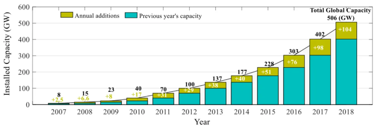
Figure 1.1: Solar PV global capacity and annual additions from 2007 to 2018…………....2
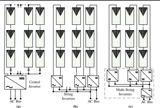
Figure 1.2: PV grid-tied systems topologies (a).Central Inverters ;( b). String Inverters and (c).Multi-String Inverters. ……….…..………...4
Figure 1.3: Block diagram of a single-stage grid-tied PV system……..……….…….4
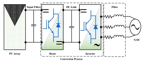
Figure 1.4: Block diagram of a two-stage grid-tied PV system……….…………5
Figure 2.1: Block diagram of two-stage grid-tied PV system………...………...12
Figure 2.2: PV array system………...………..12
Figure 2.3: The equivalent circuit of a PV cell………..…..13
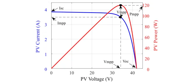
Figure 2.4: I-V and P-V characteristics of pb solar BP SX 120 module under STC……...15
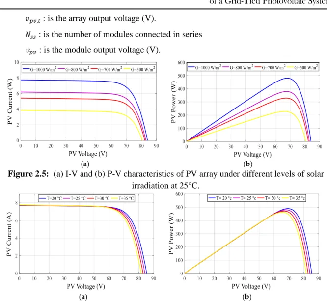
Figure 2.5: (a) I-V and (b) P-V characteristics of PV array under different levels of solar irradiation at 25°C………..……...16
Figure 2.6: (a) I-V and (b) P-V characteristics of PV array under different temperatures at 1000 W/m²……….16
Figure 2.7: Equivalent boost circuit: (a) on state; (b) off state.………..…….18
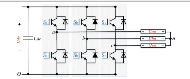
Figure 2.8: Three-phase two-level inverter topology………...21
Figure 2.9: RL filter representation………..23
FIGURE 3.1: (a) Open-circuit voltage algorithm flowchart, (b) short-circuit current algorithm flowchart …………...………...…30
Figure 3.2: (a) Conventional P&O algorithm flowchart. ………31
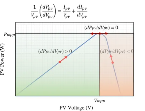
Figure 3.3: Basic idea of the IC algorithm on a Power-Voltage curve of a PV array……..32
Figure 3.4: Flowchart of the IC algorithm…………...………33
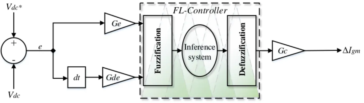
Figure 3.5: Bloc diagram of fuzzy logic controller………....34
Figure 3.6: Bloc diagram of the DC-Link voltage control based on a simple PI ………....35
ix
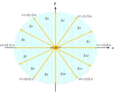
Figure 3.10: Voltage vectors generated in α-β coordinate.………..………39
Figure 3.11: Block diagram of the DPC strategy.………..………..………39
Figure 3.12: Block diagram of FCS-MPC strategy...………..…………..……...…………40
Figure 3.13: Bloc diagram of the VOC technique………41
Figure 4.1: Proposed control scheme for the PV system………..……...…………53
Figure 4.2: Flowchart of P&O voltage-based algorithm (V-MPPT)……….………..55
Figure 4.3: Block diagram of proposed sliding surface………...………58
Figure 4.4: Solar irradiation profile………...………...60
Figure 4.5: Simulated PV voltage with conventional P&O algorithm……….61
Figure 4.6: Simulated PV voltage with P&O/PI method……….61
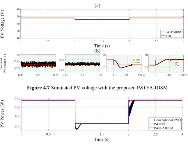
Figure 4.7: Simulated PV voltage with the proposed P&O/A-IDSM ………...……..62
Figure 4.8: PV power waveforms for: conventional P&O (black),P&O/PI (red) and proposed P&O/AIDSM (blue)………..62
Figure 4.9: Zoom of Figure 4.8...……….62
Figure 4.10: PV voltage behaviors with different damping ratio (ξ). (a) in step decrease in irradiation from 1000 W/m2to 500 W/m2, (b) in step increase in irradiation from 500 W/m2 to 1000 W/m2...……….63
Figure 4.11: Schematic of the experimental set up ………....64
Figure 4.12: Experimental responses of the PV voltage, current and power for conventional P&O ………..……….………..64
Figure 4.13: Experimental responses of the PV voltage, current and power for P&O/PI method ………..……….………..65
Figure 4.14: Experimental responses of the PV voltage, current and power for proposed control ………….………..……….……….…..65
x
Figure 5.4: V-MPPT flowchart………...……….74
Figure 5.5: Block diagram of the proposed DC-Link voltage controller based on ISMC theory……….…………77
Figure 5.6: The proposed VOC based on ISMC………..80
Figure 5.7: Solar irradiation profiles…..……….……….83
Figure 5.8: Simulation results of grid-tied PV system with the conventional control scheme; under irradiation changes. (a) PV Voltage; (b) PV Current; (c) PV Power; (d) DC−Link Voltage; (e) Id Current and (f) Iq Current………...……….87
Figure 5.9: Simulation results of grid-tied PV system with the proposed control scheme; under irradiation changes. (a) PV Voltage; (b) PV Current; (c) PV Power; (d) DC−Link Voltage; (e) Id Current and (f) Iq Current………88 Figure 5.10: PV voltages with conventional and proposed VO-MPPT methods…..……..89
Figure 5.11: Extracted PV power with conventional and proposed VO-MPPT methods...89
Figure 5.12: DC-Link voltage responses with conventional and proposed methods….….89
Figure 5.13: Grid currents and their zoom waveforms: (a) conventional control scheme; (b) proposed control schemes; under irradiation changes………..90 Figure 5.14: Comparison of: (a) grid current THD%; (b) grid current ripples; under irradiation changes………....90
Figure 5.15: Performance of conventional MPPT (based on PI controller) under irradiation changes………91
Figure 5.16: Performance of proposed MPPT under irradiation changes. ..………....92
Figure 5.17: Performance of the DC-link voltage for conventional controller under irradiation changes………93
Figure 5.18: Performance of the DC-link voltage for proposed controller under irradiation changes………93
xi
for proposed scheme under irradiation changes.……….……...94 Figure 5.21: Performance of the injected grid currents for conventional scheme under
irradiation changes………95
Figure 5.22: Performance of the injected grid currents for proposed scheme under
xii
TABLE 1.1: Standards for grid-tied PV system ………..……….………...6
TABLE 2.1: PV cell parameters ………...…………...13
TABLE 2.2: BP-MSX 120 module datasheet parameters ………...15
TABLE 2.3: The switching states in a three-phase inverter……….21
TABLE 3.1: Switching table for the DPC strategy………..39
TABLE 4.1: Parameters of the boost converter………...………59
TABLE 4.2 Key results for MPPT techniques……….61
TABLE 4.3: Key figures of the proposed scheme and other MPPT methods……...……..64
TABLE 5.1: Global system specifications ……….………...…………..84
TABLE 5.2: Comparison results for MPPT methods……….………...…………..85
xiii AC Alternative current
ANN Artificial neural network C-MPPT Current based MPPT DC Direct current
DPC Direct power control
DER Distributed energy resources
EPIA European Photovoltaic Industry Association FCS-MPC Finite control set model predictive control FLC Fuzzy logic control (controller)
GA Genetic algorithm
GSEC Global Solar Energy Council
GW Gigawatt
HIL Hardware in the loop
IGBT Insulated gate bipolar transistor IC Incremental conductance
IEC International Electro-technical Commission IEEE Institute of Electrical and Electronics Engineers ISMC Integral sliding mode control
I-V Current-voltage
KCL Kirchhoff’s Current Law KVL Kirchhoff’s Voltage Law MPC Model predictive control MPP Maximum power point
MPPT Maximum power point tracking OCV Open-circuit voltage
P&O Perturb and observe PCC Point of common coupling PI Proportional-integral
PID Proportional-integral-derivative PSO Particle swarm optimization PV Photovoltaic
xiv SCC Short-circuit current
STC Standard test conditions SMC Sliding mode control SSE Steady state error
SVM Space vector modulation THD Total Harmonic Distortion VOC Voltage oriented control V-MPPT Voltage based MPPT VO-MPPT Voltage oriented MPPT VSI Voltage source inverter
xv
Cin Boost input capacitor (µF)
Cdc Boost capacitor (µF)
𝑓𝑐 Switching frequency of the boost converter (kHz). G Solar irradiation (w/m2)
Id Diode current (A)
Iinv Inverter input voltage (A)
IL Boost input current (A)
Io Reverse saturation current of the diode (A)
Iph Photovoltaic cell photocurrent (A)
Ipv Photovoltaic array output current (A)
Ir Derived current by the shunt resistance (A)
ISC Photovoltaic array short-circuit current
k Boltzmann constant ( 23
1.38 10 − J/K)
L Boost input inductor (mH)
Lg Inverter side inductor (H).
n Diode ideality factor
Np Number of cells connected in parallel
Npp Number of modules connected in parallel
Ns Number of cells connected in series
Nss Number of modules connected in series
q Electronic charge ( 19
1.6 10 − C)
R Boost resistive load (Ω)
Rg Internal resistance of the filter (Ω)
Rs Photovoltaic cell series resistance (Ω)
Rsh Photovoltaic cell shunt resistance (Ω)
S Switching signal of the Boost converter
Sa, Sb, Sc Switching signals of the inverter.
T Absolute temperature (K)
Ts Sample time of the P&O algorithm (µs)
va,g, vb,g, vc,g Grid voltage (V)
xvi
VOC Photovoltaic array open-circuit voltage (V)
vpv Photovoltaic array output voltage (V)
Vt Thermal voltage (V)
1
Chapter 1
Introduction
1.1
I
NTRODUCTION TO PHOTOVOLTAICSTo satisfy the growing energy demand with a reduction in global warming caused by fossil fuels (natural gas, oil, coal, etc.), renewable energy sources, especially solar photovoltaic (PV) energy has attracted attention in today's world. According to the Global Solar Energy Council (GSEC) and European Photovoltaic Industry Association (EPIA) [ 1.1-2], the solar energy capacity has grown fast from 2007 to 2018 with about 104 gigawatt (GW) installed only in 2018. Figure 1.1 represents the global solar energy capacity and annual additions from 2007 to 2018 [1.2]. In fact, the global installed PV energy capacity reached 506 GW at the end of 2018 (representing an increase of 20.55% more than the previous year 2017), stating that PV energy plays an important role in the modern energy resource system [1.1]. The secret of this rapid growth in total installed capacity lies in the increased competitiveness of PV energy due to reduced prices of PV system components, especially the PV modules and the introduction of economic incentives or subsidies intended at reducing the use of fossil fuels according to the objectives of the Kyoto Protocol [1.3].
2
Figure 1.1: Solar PV global capacity and annual additions from 2007 to 2018.
Principally, PV systems can be classified into two application fields which are off-grid and grid-tied [1.4]. In off-grid applications, the PV generator is used to supply energy to remote DC or AC loads that are not attached to the electric grid which is unavailable or expensive. Similarly, storage batteries are required in this application to store excess energy. There are different manners of the use as, small-scale production systems, water pumping system [1.5].
In grid-tied applications, the energy produced from PV generator can be directly converted to AC and injected into the utility grid, where the power injection must be in accordance with internationally agreed conditions. Furthermore, this application includes two systems types which are distributed generation and centralized power systems. The first type is installed to supply power to a grid-tied customer or directly to the grid. Whilst, the other type is mainly installed to reduce greenhouse gases caused by polluted energy sources[1.6].
1.2
O
VERVIEW OF GRID-
TIED PHOTOVOLTAIC SYSTEMSOwing to the cost reduction of solar photovoltaic and the development in power electronics helps to produce electricity at high efficacy and make it possible to supply power directly to the utility grid. Currently, Grid connection is the most requested on the PV market, because there is better usage of PV energy and more energy is acquired. Also, it is not relying on energy storage devices which allows a reduced cost with less maintenance[1.7-11].
Typically, there are different management topologies for these PV systems connected to the grid. Nevertheless, the main function of these approaches is to convert the DC power generated by PV panels into grid-synchronized AC power. This processes is specified only by inverters , which is considered as the key elements of PV systems connected to the grid. The
3
progress made in the development of PV inverters allowed to a significant improvement of these management systems. The inverters are not limited only to the principal operation (DC-AC conversion), but they also exploit the current provided by the photovoltaic generator for forcing it to operate at its maximum power point. In addition, they provide reliable grid monitoring to finally protect against failures and interruptions, in case of power problems, whether the grid or the installation[1.9-11]. Currently, there are three PV power plant topologies offer good technical solutions: the centralized inverters, string inverters and multi-string inverters as shown in Figure 1.2.
In centralized inverters, a number of PV modules was assembled in series and in parallel connection, so called PV array, to provide high power levels. In this topology, a central DC-AC inverter is placed between the PV array and utility grid, as shown in Figure 1.2(a). The main benefit of the this topology is its low cost compared to other topologies, as well as the easiness of maintenance of the inverter. Nevertheless, several limitations are noted in this topology, such as significant power losses due to a centralized maximum power point tracking and mismatch losses between the photovoltaic modules [1.9-11].
In the string inverters, a number of PV modules connected in series is called string. As their name indicates, each string is attached to individual DC-AC inverter, as shown in Figure
1.2(b); consequently, the reliability of the system is improved. Additionally, since each string can operate separately at its own maximum power point, the losses due to partial shading are reduced. But, depending on the number of inverters, the main disadvantage is the expensive cost [1.9-11].
In multi-string inverters, each string is connected to its individual DC-DC converter for the maximum power point tracking and voltage amplification. All the DC-DC converters are then linked to a common DC-AC inverter via a DC bus, as shown in Figure 1.2(c). This topology encompasses the benefits of string and centralized topologies. So, the output power is increased since every string can be controlled individually, then the total cost is reduced as it uses only one inverter. Conversely, there is an increase in losses due to the DC-DC converters that are added [1.9-11].
4
Figure 1.2: PV grid-tied systems topologies a).Central Inverter; b). String Inverters; c).Multi-String Inverters.
In term of power processing stages, a grid-tied PV system can be classified into two configurations type, single and dual stages configuration[1.11-26].
In single-stage configurations, the conversion process includes only a DC-AC inverter to perform all the control tasks as maximum power point tracking (MPPT), control of grid current and voltage amplification. Thus, this configuration poses difficulties of control and implementation offering less efficiency. Different types of DC-AC inverters have been employed to improve and regulate the performance, such as two-level [1.11-14], multilevel [1.15-18], Z source voltage inverters [1.19] and split-source inverter [1.20]. Figure 1.3
illustratesthe block diagram of a single-stage grid-tied PV system.
Figure 1.3: Block diagram of a single-stage grid-tied PV system.
In two-stage configuration, the conversion process contains two stages. The first stage is the DC-DC converter used to amplify the PV array voltage and track the maximum power. To perform these operations, different types of DC-DC converters are employed such as boost
AC Bus String Inverters AC Bus Central Inverter AC Bus Multi-String Inverters (a) (b) (c)
5
[1.21-24], buck-boost[1.25] and zeta [1.26]. The second stage is the DC-AC inverter used to regulate the DC-Link voltage and to control the injected grid current. Two-stage systems provide high flexibility in control as compared to single-stage systems, since the control tasks are divided among the two converters. A block diagram of a two-stage grid-tied PV system is shown in Figure 1.4.
Figure 1.4: Block diagram of a two-stage grid-tied PV system.
1.3
S
TANDARDS FOR GRID CONNECTION OF PHOTOVOLTAIC SYSTEMSAt the first, an interconnection system is the equipment that makes up the physical link amongst distributed energy resources (DER) and the electric grid. In the grid-tied photovoltaic application, the inverter is the key element which converts the DC power into AC power. But, it also generates an important harmonic disturbance caused by its switching devices. For this purpose, the interconnection of DER with the grid is restricted by several international standards like International Electro technical Commission (IEC), Institute of Electrical and Electronics Engineers (IEEE) [1.7-11]. For uninterrupted operation within the limits specified in standards, some important terms such as total harmonic distortion, DC injection, galvanic isolation, detection and counter-voltage must be included in the frequency bands [1.27-28].
In this section, we will present briefly the most relevant standards IEC 61727 and IEEE 1547–2003. Similarly, Table 1.1 presents the parameters of these standards depending on the previous terms.
IEC 61727 standard focuses on grid-tied photovoltaic (PV) systems that use inverters based on a semiconductor device for DC to AC conversion. It provides specific recommendations for systems of 10 kVA or less that can be used in individual-home, whether single-phase or three-phase. This standard concerns the connection to the grid with low-voltage distribution, as well explained in literature [1.29] shows the necessity and important information for proper installation of PV system.
6
IEEE 1547-2003 Standard provides guidelines for the interconnection of distributed energy resources (DER) with a grid system. It provides requirements for the performance, operation, testing, security, and maintenance of the interconnection[1.30].
TABLE 1.1: Standards for grid-tied PV system.
Parameters IEC 61727 IEEE1547
THD <5% <5%
Power Factor 0.90 0.90
DC current injection
Less than 1% of rated output current
Less than 0.5 % of rated output current Voltage range for normal
operation 85 % to 110 % 88 % to 110 %
Frequency range for normal
operation 49 Hz to 51 Hz 59.3 Hz to 60.5 Hz
1.4
M
OTIVATIONThe efficiency of a grid-tied photovoltaic system depends on the choice of configurations or topologies, the types of power converters and their control. In this way, it is important to know the effect of different operating conditions on the complete power conversion chain, then deal with them, or rather to achieve the best performance from each system element under any operating conditions. Also, it is necessary to design an effective controller able to harvest as much as possible the produced energy from the photovoltaic generator under changing atmospheric conditions, then to inject it into the electrical grid with a high quality. In other hand, it is due to the high flexibility in the control provided by two-stage grid-tied PV systems. Hence, in each control part, several controller schemes have been proposed in the literature; nevertheless, most of those controllers suffer from disadvantages.
The motivation for this thesis is to develop new control strategies that are simple and robust to working condition changes. The proposed strategies are based on sliding mode control theory and involve three control parts. The MPPT methods should be capable of extracting maximum power from the PV array taking into account all the challenges that are existing in the literature (e.g. sudden changing atmospheric conditions, tracking accuracy, etc.). Then, the DC-AC inverter in the system should have a good DC-Link controller, which can offer fast transient response and high control accuracy. Finally, the current injected into the electrical grid must have a low total harmonic distortion (THD <5%) in accordance with international limits.
7
1.5
S
TRUCTURE OF THE THESISBeside the current chapter, the remaining of the thesis is structured asfollows:
Chapter-2: This chapter provides the modeling and sizing of all constituent elements in a two-stage grid-tied photovoltaic system. Because these procedures are used in the later chapters for clarifying the control design and simulation work.
Chapter-3: This chapter presents a comprehensive review of the maximum power point tracking (MPPT) control, the DC-Link voltage regulation, and the injected grid current control for two-stage grid-tied PV system.
Chapter-4:This chapter presents a maximum power point tracking technique based on sliding mode control. The proposed adaptive integral derivative sliding mode controller is combined with voltage based on perturb and observe algorithm. Numerical simulations and real-time hardware in the loop implementations are provided to validate the performance enhancement of the proposed schemes.
Chapter-5: This chapter presents a robust control of two-stage grid-tied photovoltaic system. The overall proposed control scheme based on the integral sliding mode control theory. Numerical simulations and real-time hardware in the loop implementation are provided to validate the performance enhancement of the proposed control scheme.
Chapter-6: This chapter presents the summary and conclusion of the thesis. Moreover, this chapter describes the contributions of the thesis presented and possible extensions to the research presented in this thesis.
8
R
EFERENCES[1.1] Renewable Energy Policy Network for the 21st Centuray (REN21), 2018. Global Solar Energy Council (GSEC). [Online]. Available: http://www.ren21.net/.
[1.2] European Photovoltaic Industry Association (EPIA), 2012, Global Market Outlook for Photovoltaics until 2018. [Online]. Available: http://www.epia.org/.
[1.3] Romero-Cadaval, E., Spagnuolo, G., García Franquelo, L., Ramos-Paja, C.A., Suntio, T. and Xiao, W.M., 2013. Grid Connected Photovoltaic Generation Plants. Components and Operation. IEEE Industrial Electronics Magazine, 7 (3), 6-20.
[1.4] Madeti, S.R., Singh, S.N., 2017. Monitoring system for photovoltaic plants: A review. Renew. Sustain. Energy Rev. 67, 1180–1207.
[1.5] Talbi, B., 2018. Contribution à l’Amélioration de la commande d’un système de pompage photovoltaïque. PhD. thesis, University of Ferhat Abbas Sétif 1.
[1.6] Kouro, S., Leon, J.I., Vinnikov, D. and Franquelo, L.G., 2015. Grid-connected photovoltaic systems: An overview of recent research and emerging PV converter technology. IEEE Industrial Electronics Magazine, 9(1), 47-61.
[1.7] Teodorescu, R., Liserre, M. and Rodriguez, P., 2011. Grid converters for photovoltaic and wind power systems (Vol. 29). John Wiley & Sons.
[1.8] Zhang, L., Sun, K., Xing, Y., Feng, L. and Ge, H., 2011. A modular grid-connected photovoltaic generation system based on DC bus. IEEE transactions on power electronics, 26(2), 523-531.
[1.9] Omran, W., 2010. Performance analysis of grid-connected photovoltaic systems. PhD. thesis, University of Waterloo.
[1.10] Abu-Rub, H., Malinowski, M. and Al-Haddad, K., 2014. Power electronics for renewable energy systems, transportation and industrial applications. John Wiley & Sons.
[1.11]Malek, H., 2014. Control of grid-connected photovoltaic systems using fractional order operators. PhD. thesis, University of Utah State.
9
[1.12] Libo, W., Zhengming, Z. and Jianzheng, L., 2007. A single-stage three-phase grid-connected photovoltaic system with modified MPPT method and reactive power compensation. IEEE Transactions on Energy Conversion, 22(4), 881-886.
[1.13] Libo, W., Zhengming, Z. and Jianzheng, L., 2007. A single-stage three-phase grid-connected photovoltaic system with modified MPPT method and reactive power compensation. IEEE Transactions on Energy Conversion, 22(4), 881-886.
[1.14] Shayestehfard, A., Mekhilef, S. and Mokhlis, H., 2017. IZDPWM-based feedforward controller for grid-connected inverters under unbalanced and distorted conditions. IEEE Transactions on Industrial Electronics, 64(1), 14-21.
[1.15] Selvaraj, J. and Rahim, N.A., 2009. Multilevel inverter for grid-connected PV system employing digital PI controller. IEEE transactions on industrial electronics, 56(1), 149-158.
[1.16] Jain, S. and Sonti, V., 2017. A highly efficient and reliable inverter configuration based cascaded multilevel inverter for PV systems. IEEE Transactions on Industrial Electronics, 64(4), 2865-2875.
[1.17] Kim, J.S., Kwon, J.M. and Kwon, B.H., 2018. High-efficiency two-stage three-level grid-connected photovoltaic inverter. IEEE Transactions on Industrial Electronics, 65(3), 2368-2377.
[1.18] Rojas, F., Kennel, R., Cardenas, R., Repenning, R., Clare, J.C. and Diaz, M., 2017. A new space-vector-modulation algorithm for a three-level four-leg NPC inverter. IEEE Transactions on Energy Conversion, 32(1), 23-35.
[1.19] Hanif, M., Basu, M. and Gaughan, K., 2011. Understanding the operation of a Z-source inverter for photovoltaic application with a design example. IET Power Electronics, 4(3), 278-287.
[1.20] Abdelhakim, A., Mattavelli, P., Boscaino, V. and Lullo, G., 2017. Decoupled control scheme of grid-connected split-source inverters. IEEE Transactions on Industrial Electronics, 64(8), 6202-6211.
[1.21] Singh, A.K., Hussain, I. and Singh, B., 2018. Double-stage three-phase grid-integrated solar PV system with fast zero attracting normalized least mean fourth based adaptive control. IEEE Transactions on Industrial Electronics, 65(5), 3921-3931.
10
[1.22] Chen, Y. and Smedley, K., 2008. Three-phase boost-type grid-connected inverter. IEEE Transactions on Power Electronics, 23(5), 2301-2309.
[1.23] Sebaaly, F., Vahedi, H., Kanaan, H.Y., Moubayed, N. and Al-Haddad, K., 2016. Design and implementation of space vector modulation-based sliding mode control for grid-connected 3L-NPC inverter. IEEE Transactions on Industrial Electronics, 63(12), 7854-7863.
[1.24] Hu, Y., Du, Y., Xiao, W., Finney, S. and Cao, W., 2015. DC-link voltage control strategy for reducing capacitance and total harmonic distortion in single-phase grid-connected photovoltaic inverters. IET Power Electronics, 8(8), 1386-1393.
[1.25] Chomsuwan, K., Prisuwanna, P. and Monyakul, V., 2002, May. Photovoltaic grid-connected inverter using two-switch buck-boost converter. In Conference Record of the Twenty-Ninth IEEE Photovoltaic Specialists Conference, 2002. (pp. 1527-1530). IEEE.
[1.26] Lopez, H.F.M., Viero, R.C., Zollmann, C., Tonkoski, R., Reckzielgel, L., Gomes, H. and Dos Reis, F.S., 2009, October. Analog signal processing for photovoltaic panels grid-tied by Zeta converter. In 2009 IEEE Electrical Power & Energy Conference (EPEC) (pp. 1-6). IEEE.
[1.28] Francisco, C.D.L.R., 2015. Harmonics, Power Systems, and Smart Grids. CRC press.
[1.27] Karimi, M., Mokhlis, H., Naidu, K., Uddin, S. and Bakar, A.H.A., 2016. Photovoltaic penetration issues and impacts in distribution network–A review. Renewable and Sustainable Energy Reviews, 53, 594-605.
[1.29] Rangarajan, S.S., Collins, E.R., Fox, J.C. and Kothari, D.P., 2017, February. A survey on global PV interconnection standards. In 2017 IEEE Power and Energy Conference at Illinois (PECI) (pp. 1-8). IEEE.
[1.30] Obi, M. and Bass, R., 2016. Trends and challenges of grid-connected photovoltaic systems–A review. Renewable and Sustainable Energy Reviews, 58, 1082-1094.
11
Chapter 2
Description, Modeling and
Sizing the overall elements of
a Grid-Tied Photovoltaic
System
2.1
I
NTRODUCTIONAs mentioned previously, two-stage grid-tied PV system is a capable solution that ensuring the appropriate conversion of PV energy over a wide range. Figure 2.1 describes a common schematic principle for a two- stage grid-tied photovoltaic (PV) system. The different elements of this configuration are classified as following; the PV array formed by a group of PV module connected in series and parallel, which is used to produce the electrical energy through the photovoltaic effect. The input filter is used to decrease the oscillatory nature of power achieved from PV array. DC-DC boost converter, which is used to amplify the voltage of the PV array and track the maximum power. The DC-Link capacitor (or power decoupling) is placed between the output of DC-DC boost converter and DC-AC inverter input. The inverter is used to transform the DC voltage to AC voltage. The inductor filter is then used to provide a suitable coupling with the grid and reduce the current fluctuations in the lines.
After having mentioned all the components of the two-stage grid-tied PV system, as well as the role of its components on the PV system, we proceed to modeling our system. The modeling step is important and requires a set of equations that describe all elements of the studied system. In this chapter, we will represent the mathematical model of PV array, boost converter, inverter, L-filter and electrical grid. Also, we will size the value of the electrical components such as, the input capacitor, the boost inductor and the DC-Link capacitor.
12
Figure 2.1: Block diagram of two-stage grid-tied PV system.
2.2
M
ODELING OF PHOTOVOLTAIC ARRAYThe basic element of a PV array system is the PV cell. Where, cells may be assembled to form PV modules which in turns assembled to form PV arrays as illustrated in Figure 2.2. The series and parallel PV modules provide the required voltage and current.
Figure 2.2: PV array system.
2.2.1Electrical Model of a PV Cell
The PV cell is semiconductor devices that convert sunlight to electricity through photovoltaic effect. The modeling of PV cell necessarily involves a careful choice of equivalent electrical circuits. Several mathematical models have been developed to represent a strongly nonlinear behavior, resulting from that of the semiconductor junctions which are at the base of their realizations. These models differ from each other by the mathematical
PV Array Input Filter Boost Inverter DC-Link Filter Grid Conversion Process
=
˷
=
=
13
procedures and the number of parameters involved in the calculation of the voltage and current of the photovoltaic module [2.1-5]. A single diode electric model is the most quoted in the literature, the photovoltaic module is characterized by its equivalent electrical circuit as illustrated in Figure 2.3 which consists of a current source that models the conversion of light flux into electrical energy, a shunt resistor (𝑅𝑠ℎ) is a consequence of the surface state along
the periphery of the cell, a series resistance (𝑅𝑠).
Figure 2.3: The equivalent circuit of a PV cell.
TABLE 2.1: PV cell parameters
Variables Parameter
𝒊𝒑𝒉 Cell photocurrent (A).
𝒊𝒅 Diode current (Shockley equation) (A). 𝒊𝒓 Derived current by the shunt resistance (A).
𝒗𝒑𝒗 Cell output voltage (V) 𝒊𝒑𝒗 Cell output current (A)
𝑹𝒔 Cell series parasitic resistance (Ω).
𝑹𝒔𝒉 Cell shunts parasitic resistance (Ω).
𝒒 Electronic charge (1.6 10 −19C)
𝑻 Absolute temperature (K).
𝒌 Boltzmann constant (1.38 10 −23J/K).
𝒏 Diode ideality factor
𝒊𝒐 Reverse saturation current of the diode (A).
i ph i d ri ipv v pv Rs R sh
14
In view of that, the current to the load can be given as [2.1]:
𝑖𝑝𝑣 = 𝑖𝑝ℎ− 𝑖𝑑− 𝑖𝑟 = 𝑖𝑝ℎ− 𝑖𝑜[𝑒
𝑞(𝑣𝑝𝑣+𝑅𝑠 𝑖𝑝𝑣)
𝑛 𝑘 𝑇 − 1] − 𝑣𝑝𝑣+ 𝑅𝑠𝑖𝑝𝑣 𝑅𝑠ℎ
(2.1)
Where 𝑖𝑝𝑣 is the output current of the PV cell, which is a function of its output voltage 𝑣𝑝𝑣, and a number of variables as defined in Table 2.1.
2.2.2 PV Module I-V and P-V Characteristics
Typically, each individual PV cells gives a small power which makes it insufficient for the majority of PV applications. To provide the required power, several PV cells connected either in series or parallel are grouped to form PV module. The performance of PV modules is generally evaluated based on their maximum DC output power under standard test conditions (STC). The standard test conditions are defined by an operating temperature of the PV cell of 25 °C and an incident solar irradiance level of 1000 W / m2. For PV modules, assuming all cells are identical and under uniform irradiance and temperature. The current expression of PV module 𝑖𝑝𝑣,𝑚 can be written as [2.1]:
𝑖𝑝𝑣,𝑚= 𝑁𝑝 𝑖𝑝ℎ− 𝑁𝑝 𝑖𝑜[𝑒 𝑁𝑠 𝑣𝑝𝑣+(𝑁𝑠/𝑁𝑝)𝑅𝑠 𝑖𝑝𝑣 𝑁𝑠 𝑛 𝑣𝑡 − 1] − 𝑁𝑠 𝑣𝑝𝑣+ (𝑁𝑁𝑠 𝑝)𝑅𝑠𝑖𝑝𝑣 (𝑁𝑠 𝑁𝑝) 𝑅𝑠ℎ (2.2) Where:
𝑁𝑠 : is the number of cells connected in series 𝑁𝑝 : is the number of cells connected in parallel
Different types of PV modules exist for different applications. In this thesis, the BP-MSX 120 of 120 Wp, is considered. The datasheet values for this module are represented in Table
2.2. Moreover, Figure 2.4 shows the current-voltage (I-V) and Power-voltage (P-V) characteristics of the considered PV module at STC mode. From (I-V) and (P-V) characteristic, it can be distinguished three operating points of the PV module; short-circuit current (ISC) which is corresponding to zero voltage, another extreme point corresponding to
zero current which called the open-circuit voltage (VOC). Whilst, the third operating point is
the optimal operating point MPP. These operating points are particular interest to define the performance of each PV module.
15
Figure 2.4: I-V and P-V characteristics of solar BP-SMX 120 module under STC.
TABLE 2.2: BP-MSX 120 module datasheet parameters [2.6]:
PV array Values (STC)
Open-circuit voltage (Voc) 42.1 V
Optimum operating voltage (Vmpp) 33.7 V
Short-circuit current (Isc) 3.87 A
Optimum operating current (Impp) 3.56 A
Maximum power (Pmpp) 120 Wp
Temperature coefficient of Voc -0.160 V/°C
Temperature coefficient of Isc 0.065 %/°C
2.2.3 PV Array
Multiple modules can be wired together in series and parallel to deliver the required voltage and current. The group of connected modules is called a PV array. From equations (2.3) and (2.4), the output current and voltage of a PV array can be calculated as [2.7]:
𝑖𝑝𝑣,𝑡= 𝑁𝑝𝑝 𝑖𝑝𝑣,𝑚 (2.3)
𝑣𝑝𝑣,𝑡= 𝑁𝑠𝑠 𝑣𝑝𝑣,𝑚 (2.4)
where:
𝑖𝑝𝑣,𝑡: is the array output current (A).
𝑁𝑝𝑝: is the number of modules connected in parallel 𝑖𝑝𝑣 : is the module output current (A).
16
𝑣𝑝𝑣,𝑡: is the array output voltage (V).
𝑁𝑠𝑠: is the number of modules connected in series 𝑣𝑝𝑣 : is the module output voltage (V).
(a) (b)
Figure 2.5: (a) I-V and (b) P-V characteristics of PV array under different levels of solar irradiation at 25°C.
(a) (b)
Figure 2.6: (a) I-V and (b) P-V characteristics of PV array under different temperatures at 1000 W/m².
According to our consideration, the PV array is formed by four PV modules BP-MSX 120 connected 2 × 2 in series and in parallel. To display the effect of irradiation and temperature variations on the PV array, the (I–V) and (P–V) characteristics are usually introduced in order to present the electrical behavior of PV array. In Figure 2.5, a strong dependence links the PV array current to the irradiation which affects strongly the MPP of the PV array. Nevertheless, the voltage increases a little bit when the solar irradiation G is increased. In contrast, as shown in Figure 2.6, the temperature change has little effect on the MPP of the PV array. Also, it is worth noting that the temperature variations during the day are generally not important.
17
2.3
S
IZING OF THE INPUT CAPACITANCEThe input capacitor is connected in parallel amongst the PV array and the boost converter, which is used to decrease the oscillatory nature of power achieved from PV array. As discussed in the previous section, in case of variation in temperature and irradiation, the capacitance will see the voltage ripple from the PV array MPP as ∆𝑣𝑝𝑣, as irradiation change
from 500 w/m2 to 1000 w/m2 , the (𝑉
𝑜𝑐) of PV array also sees these variations and change by, ∆𝑣𝑝𝑣 = 2 𝑉. So, the input capacitance can be obtained using the analysis which assumes the
continuous conduction mode (CCM) of the boost converter [2.8].
∆𝑣𝑝𝑣 =
𝐷. 𝑣𝑝𝑣 4. 𝑓𝑐2. 𝐿. 𝐶𝑖𝑛
(1.5)
Thus, the input capacitance can be estimated as;
𝐶𝑖𝑛 =
𝐷. 𝑣𝑝𝑣
4. 𝑓𝑐2. 𝐿. ∆𝑣𝑝𝑣 (2.6)
With 𝐷 is the duty cycle of the boost converter and given by;
𝐷 = 1 −𝑣𝑝𝑣
𝑣𝑑𝑐 (2.7)
Where:
𝑣𝑝𝑣: is the boost input voltage (V). 𝑣𝑑𝑐: is the boost output voltage (V). 𝑖𝑝𝑣: is the photo-generated current (A).
L: is the boost input inductor (mH). 𝐶𝑖𝑛: is the input capacitor (µF).
𝑓𝑐: is the switching frequency of the boost converter (kHz).
2.4
P
OWER CONVERTERS STAGEAs known, the power converters are used to regulate the transit of electrical energy from the source to the receiver with possibly modifying the form in which this energy is presented. In PV system application, the power converter has more attention due to its control flexibility. Where, in two-stage grid-tied PV system, the conversion process consists of two stages converter (DC-DC and DC-AC converters). The first one is used to amplify the voltage of the PV array and to track the maximum power, because the energy produced by PV systems is
18
adversely affected by unstable weather conditions. The second stage is the DC-AC inverter used to inject the PV power into the electrical grid [2.9], as shown in Figure 2.1.
2.4.1 DC-DC Boost Converter Modeling
The DC-DC boost converter is usually used in PV systems for tracking the MPP produced by the PV array due to some of its important features, such as simplicity, robustness, and continuous input current. Figure 2.7 shows the equivalent boost circuits for both on and off switching states, with the state variables chosen as: 𝑖𝐿 and 𝑣𝑝𝑣.
Figure 2.7: Equivalent boost circuit: (a) on state; (b) off state.
State on: when the IGBT conducting, the diode is in open circuit (Figure 2.7(a)), the state variables equations can be modeled as:
{ 𝑑𝑣𝑝𝑣 𝑑𝑡 = 𝑖𝑝𝑣− 𝑖𝐿 𝐶𝑖𝑛 𝑑𝑖𝐿 𝑑𝑡 = 𝑣𝑝𝑣 𝐿 (2.8)
State off: the IGBT in this case is considered as open (Figure 2.7(b)), the preceding equation system can be rewritten as:
{ 𝑑𝑣𝑝𝑣 𝑑𝑡 = 𝑖𝑝𝑣− 𝑖𝐿 𝐶𝑖𝑛 𝑑𝑖𝐿 𝑑𝑡 = 𝑣𝑝𝑣− 𝑣𝑑𝑐 𝐿 (2.9)
The dynamic model of the boost converter in term of duty cycle "𝐷" can be expressed, using averaging method presented in [2.10], as
ipv iL i C in v pv v dc iinv Boost Converter S=0 iout i dc (b) ipv iL i c in v pv v dc iinv Boost Converter S=1 (a)
19 { 𝑑𝑣𝑝𝑣 𝑑𝑡 = 𝑖𝑝𝑣− 𝑖𝐿 𝐶𝑖𝑛 𝑑𝑖𝐿 𝑑𝑡 = 𝑣𝑝𝑣 − 𝑣𝑑𝑐+ 𝐷𝑣𝑑𝑐 𝐿 (2.10) Where:
𝑖𝐿: is the boost input current (A). 𝑣𝑝𝑣: is the boost input voltage (V). 𝑣𝑑𝑐: is the boost output voltage (V). 𝑖𝑝𝑣: is the photo-generated current (A).
L: is the boost input inductor (mH). 𝐶𝑖𝑛: is the input capacitor (µF).
𝐷 : is the duty cycle considered as input variable.
2.4.1.1 Sizing of Boost Inductor
The inductor value is usually provided in the datasheet according to the required application. However, it is possible to estimate this value directly and without datasheet by using the following equation [2.11-12].
𝐿 = 𝑣𝑝𝑣 𝛥𝑖𝐿 . 𝑓𝑐
(𝑣𝑑𝑐− 𝑣𝑝𝑣 𝑣𝑑𝑐
) (2.11)
Thus, the value of inductor ripple current 𝛥𝑖𝐿 can be estimated as;
𝛥𝑖𝐿 = 𝜀𝑖. 𝑖𝑝𝑣,𝑚𝑎𝑥 (
𝑣𝑑𝑐 𝑣𝑝𝑣
) (2.12)
Where;
𝜀𝑖 : is a percentage of 20% to 40% of the maximum output current generated by the PV
array 𝑖𝑝𝑣,𝑚𝑎𝑥 ,
𝑓𝑐 : is the switching frequency (KHz),
𝑣𝑑𝑐 : is the desired DC-Link output voltage (V),
𝐿 : is the boost inductor (mH),
20
2.4.1.2 Sizing of DC-Link Capacitor
Firstly, the DC-Link voltage must be regulated to a desired value higher than the grid peak voltage to ensure transfer of produced PV power into the grid, the 𝑉𝑑𝑐 reference is estimated as follows:
𝑉𝑑𝑐∗ = 𝜇 √3 𝑉
𝑚 ,where µ > 1 (2.13)
Then, the DC-Link capacitor can be sized according to the following equation [2.11-12]. 𝐶𝑑𝑐 = 𝑝𝑝𝑣
2 . 𝜔 . 𝑉𝑑𝑐∗ . 𝛥𝑉 (2.14)
Where,
𝛥𝑉 : is the amplitude of voltage ripple, then equal to 10% of grid peak voltage ( 𝑉𝑚), 𝑝𝑝𝑣 : is the nominal power of PV modules,
𝜔 : is the rotational frequency of the generated sine wave, 𝑉𝑑𝑐∗ : is the mean voltage across the capacitor.
2.3.2 DC-AC Inverter Model
The PV inverter is the key part of grid-tied PV power systems. The main role is to convert the harvested PV power from DC form into grid-synchronized AC form and controls the power flow between the DC-DC boost converter and the grid by controlling the current injected into the grid. Depending on the PV power plant configuration, there are some PV inverter topologies and categories; a two-level voltage source inverter (VSI) is one of them. Where, six switches are used in the main circuit, each composed traditionally of a power insulated gate bipolar transistor (IGBT) and a free-wheeling diode to provide bidirectional current flow and a unidirectional voltage blocking capability, as presented in Figure 2.8. To avoid the short-circuit of the DC-Link; both of the switches in the same leg must be turned in a complementary mode [2.10-13].
21
Figure 2.8: Three-phase two-level inverter topology.
The inverter has eight switch states given in Table 2.3, two of these switch states provide zero AC line voltage at the output. In this case, the AC line currents freewheel through either the upper or lower components. The other states provide no zero AC output line voltages. In order to generate a given voltage waveform, the inverter switches from one state to another. Thus the resulting AC output line voltages consist of discrete values of voltages, which are" − 𝑣𝑑𝑐", "0", and"𝑣𝑑𝑐" [2.13].
TABLE 2.3: The switching states in a three-phase inverter.
𝑺𝒂 𝑺𝒃 𝑺𝒄 𝒗𝒂𝒃 𝒗𝒃𝒄 𝒗𝒄𝒂 0 0 0 0 0 0 0 0 1 0 −𝑣𝑑𝑐 𝑣𝑑𝑐 0 1 0 −𝑣𝑑𝑐 𝑣𝑑𝑐 0 0 1 1 −𝑣𝑑𝑐 0 𝑣𝑑𝑐 1 0 0 𝑣𝑑𝑐 0 −𝑣𝑑𝑐 1 0 1 𝑣𝑑𝑐 −𝑣𝑑𝑐 0 1 1 0 0 𝑣𝑑𝑐 −𝑣𝑑𝑐 1 1 1 0 0 0
By assuming that the switches and diodes are ideal, the composite voltages (𝑣𝑎𝑏, 𝑣𝑏𝑐, 𝑣𝑐𝑎 ) are obtained from these relationships:
{ 𝑣𝑎𝑏 = 𝑣𝑎𝑂− 𝑣𝑏𝑂 𝑣𝑏𝑐 = 𝑣𝑏𝑂 − 𝑣𝑐𝑂 𝑣𝑐𝑎 = 𝑣𝑐𝑂− 𝑣𝑎𝑂 (2.15) Where; Cdc a b c n
v
anv
bnv
cn O Sa Sa Sb Sb Sc Scv
dc22
𝑣𝑎𝑜, 𝑣𝑏𝑜, 𝑣𝑐𝑜 are the phase-to-neutral voltages of the inverter. The point "O" is taken
as a reference for these last voltages.
The three voltages at the continuous input are given by the following relations:
{
𝑣𝑎𝑂 = 𝑣𝑎𝑛− 𝑣𝑛𝑜
𝑣𝑏𝑂 = 𝑣𝑏𝑛− 𝑣𝑛𝑜 𝑣𝑐𝑂 = 𝑣𝑐𝑛− 𝑣𝑛𝑜
(2.16)
Where 𝑣𝑎𝑛, 𝑣𝑏𝑛, 𝑣𝑐𝑛 are the output voltages of the inverter (phase voltages) and 𝑣𝑛𝑂 is the
neutral voltage of the load related to "O" point.
As we are dealing with balanced voltages, which means
𝑣𝑎𝑛+ 𝑣𝑏𝑛+ 𝑣𝑐𝑛 = 0 (2.17)
By replacing equation (2.17) into equation (2.16), we get 𝑣𝑛𝑂 = 1
3(𝑣𝑎𝑂+ 𝑣𝑏𝑂+ 𝑣𝑐𝑂) (2.18) Then replacing equation (2.18) in equation (2.16) we get:
{ 𝑣𝑎𝑛 = 1 3(2𝑣𝑎𝑂− 𝑣𝑏𝑂 − 𝑣𝑐𝑂) 𝑣𝑏𝑛 = 1 3(2𝑣𝑏𝑂− 𝑣𝑎𝑂− 𝑣𝑐𝑂) 𝑣𝑐𝑛 =1 3(2𝑣𝑐𝑂− 𝑣𝑎𝑂− 𝑣𝑏𝑂) (2.19)
The inverter output voltages can be expressed in terms of DC-Link voltage and switching states as follows [2.10]: { 𝑣𝑎𝑂 = 𝑣𝑑𝑐. 𝑆𝑎 𝑣𝑏𝑂 = 𝑣𝑑𝑐. 𝑆𝑏 𝑣𝑐𝑂 = 𝑣𝑑𝑐. 𝑆𝑐 (2.20)
By replacing the previous equation into equation (2.20), equation (2.19) becomes, ( 𝑣𝑎𝑛 𝑣𝑏𝑛 𝑣𝑐𝑛) = 𝑣𝑑𝑐 3 [ 2 −1 −1 −1 2 −1 −1 −1 2 ] . [ 𝑆𝑎 𝑆𝑏 𝑆𝑐 ] (2.21) where: , , a b c
S S S : are the switching signals of the inverter,
23
2.5
G
RID SIDE FILTER MODELLINGThe inverter cannot be directly coupled to the grid, because the inverter is based on switching devices and gating signals in the form of pulses must be provided for the switches, which led to an important harmonic disturbance on the output current which degrades power quality. For this reason, in this design, the connection of the inverter to the grid is done through a first-order LR-filter in order to reduce the harmonics present in the current as shown in Figure 2.9, respect the alternation of sources and to prevent the components, so that it is within limits set by the standards that are in place for grid connection of PV system [2.14].
Figure 2.9: RL filter representation.
By applying Kirchhoff's voltage law (KVL), each phase at the connection point of the filter gives the equations which link the voltages modulated by the converter and the currents passing through the filter:
{ 𝑣𝑎𝑛 = 𝑅𝑔. 𝑖𝑎𝑔+ 𝐿𝑔 𝑑𝑖𝑎𝑔 𝑑𝑡 + 𝑉𝑎,𝑔 𝑣𝑏𝑛 = 𝑅𝑔. 𝑖𝑏𝑔+ 𝐿𝑔𝑑𝑖𝑏𝑔 𝑑𝑡 + 𝑉𝑏,𝑔 𝑣𝑐𝑛 = 𝑅𝑔. 𝑖𝑐𝑔+ 𝐿𝑔𝑑𝑖𝑐𝑔 𝑑𝑡 + 𝑉𝑐,𝑔 (2.22) From where; { 𝑑𝑖𝑎𝑔 𝑑𝑡 = 1 𝐿𝑔(𝑣𝑎𝑛− 𝑉𝑎,𝑔− 𝑅𝑔. 𝑖𝑎𝑔) 𝑑𝑖𝑏𝑔 𝑑𝑡 = 1 𝐿𝑔 (𝑣𝑏𝑛− 𝑉𝑏,𝑔− 𝑅𝑔. 𝑖𝑏𝑔) 𝑑𝑖𝑐𝑔 𝑑𝑡 = 1 𝐿𝑔(𝑣𝑐𝑛− 𝑉𝑐,𝑔− 𝑅𝑔. 𝑖𝑐𝑔) (2.23)
To calculate the inductor “𝐿𝑔” values, considering all the calculations are made for a single phase, the inverter side inductor is estimated as [2.14],
Rg Lg v an iag ibg icg n v bn v cn Va ,g V b ,g V c, g
24 𝐿𝑔 = √3. 𝑚. 𝑣𝑑𝑐
12. ℎ. 𝑓𝑠. ∆𝑖𝐿𝑔 (2.24)
Then, "∆𝑖𝐿𝑔" denotes a ripple current of 5% of the rated current.
Where;
𝐿𝑔 : is the inverter side inductor (mH),
𝑅𝑔 : is the internal resistance of the filter (Ω), 𝑓𝑠 : is the switching frequency of the inverter (Hz), 𝑣𝑑𝑐: is the desired DC-Link voltage (V),
ℎ: is the overloading factor, which value equal to1.2, 𝑚: is the modulation indices chosen between [0.5-1].
2.5
GRID MODELLINGIn any electrical system, loads are the elements that consume electrical energy. Then, the consumption of this electrical power depends on the characteristics of the load. A correct modeling of these characteristics is essential to represent finely the behavior of the load connected to the inverter. In our work, the electrical grid is considered as a load and a mathematical model of three-phase voltage source can be expressed by the following equations. { 𝑉𝑎,𝑔(𝑡) = 𝑉𝑚. √2. sin(𝑤𝑡) 𝑉𝑏,𝑔(𝑡) = 𝑉𝑚. √2. sin (𝑤𝑡 − 2𝜋 3) 𝑉𝑐,𝑔(𝑡) = 𝑉𝑚. √2. sin (𝑤𝑡 −4𝜋 3 ) (2.25) Where,
𝑉𝑎,𝑔(𝑡), 𝑉𝑏,𝑔(𝑡) and 𝑉𝑐,𝑔(𝑡) : are the grid voltages (V),
𝑤 : is the angular frequency (rad/s),
𝑉𝑚 : is the max value of grid peak voltage (V).
2.6
C
ONCLUSIONThe main purpose of this chapter is to modeling and sizing the different components of the PV plant, including in the proposed grid-tied PV system. This step is necessary for the control system and simulation work in the next chapters. Firstly, the mathematical model of; the photovoltaic cell, module and array, and their characteristic curves have been defined.
25
Then, the electrical circuit and the mathematical model of the power converter used in the proposed system have been presented. Moreover, the L-filter and the electrical grid are modeled to facilitate the injection control operation. Finally, an approach to estimate the component size such as, input capacitor, boost inductor, DC-Link capacitor and output filter (L-filter) has been presented, which in turns allows to simplify the sizing calculation of the proposed system in the next chapter.
26
R
EFERENCES[2.1] Villalva, M.G., Gazoli, J.R., Filho, E.R., 2009. Comprehensive approach to modeling and simulation of photovoltaic arrays. IEEE Trans. Power Electron. 24, 1198– 1208.
[2.2] Farivar, G., Asaei, B., 2011. A new approach for solar module temperature estimation using the simple diode model. IEEE Trans. Energy Convers. 26 (4), 1118–1126.
[2.3]Rekioua, D., Matagne, E., 2012. Optimization of Photovoltaic Power Systems. Springer Verlag.
[2.4] Bishop, J.W., 1988. Computer simulation of the effects of electrical mismatches in photovoltaic cell interconnection circuits. Solar Cells 25, 73–89.
[2.5] Kassis, A., Saad, M., 2010. Analysis of multi-crystalline silicon solar cells at low illumination levels using a modified two-diode model. Solar Energy Materials and Solar Cells 94 (12), 2108–2112.
[2.6] BP Solar Arrays Datasheet, 2001. [Online]. Available: http://www.eastcountysolar. com/pdf/BPSX120.pdf.
[2.7] Alajmi, B., 2013. Design and control of photovoltaic systems in distributed generation. PhD. thesis, University of Strathclyde.
[2.8] Gao, F., Li, D., Loh, P.C., Tang, Y. and Wang, P., 2009, September. Indirect dc-link voltage control of two-stage single-phase PV inverter. In 2009 IEEE energy conversion congress and exposition. 1166-1172.
[2.9] Abu-Rub, H., Malinowski, M., Al-Haddad, K., 2014. Power electronics for renewable Energy systems, transportation and industrial applications. John Wiley & Sons.
[2.10] Luo, F. L., Ye, H., 2004. Advanced DC-DC converters. CRC Press Boca Raton.
[2-11] Singh, A.K., Hussain, I. and Singh, B., 2018. Double-stage three-phase grid-integrated solar PV system with fast zero attracting normalized least mean fourth based adaptive control. IEEE Transactions on Industrial Electronics. 65(5), 3921-3931.
[2-12] Massawe, H.B., 2013. Grid Connected Photovoltaic Systems with SmartGrid functionality (Master's thesis, Institutt for elkraftteknikk).
27
[2-13] Orłowska-Kowalska, T., Blaabjerg, F. and Rodríguez, J. eds., 2014. Advanced and intelligent control in power electronics and drives (Vol. 531). Springer.
[2.14] Singh, B., Chandra, A. and Al-Haddad, K., 2014. Power quality: problems and mitigation techniques. John Wiley & Sons.
28
Chapter 3
An Overview on Control of
Two Stage Grid-Tied PV
Systems
3.1
I
NTRODUCTIONThe efficiency of complete power conversion chain depends not only on the types of power converters and their configurations or topologies, but also on the control scheme applied. In the present chapter, the two stage grid-tied photovoltaic (PV) configurations have been studied. The typical control requirements for this configuration included maximum power point tracking (MPPT), DC-Link voltage control, grid synchronization, and control of power injected into the grid. The main purpose of these control tasks is to confirm that the grid-tied PV system is working at the MPP during different operating conditions as well as to ensure injection of the produced power into the electrical grid with minimum loss and low total harmonic distortion at all operating points.
This chapter gives an overview of control structures for two stage grid-tied PV systems. In the first section, the concepts of numerous conventional and advanced MPPT methods are described. In the second section, the different control designs of DC-Link voltage are presented. The third section presents a brief description of used phase looked loop (PLL) to synchronize the PV system with utility grid. Finally, the last section gives an overview of the state of the art in grid-tied inverter control and highlights acknowledged weakness in these methods.