OATAO is an open access repository that collects the work of Toulouse
researchers and makes it freely available over the web where possible
Any correspondence concerning this service should be sent
to the repository administrator:
[email protected]
This is an author’s version published in:
http://oatao.univ-toulouse.fr/21786
To cite this version:
Rozier, Patrick
and Iwama, Etsuro and Nishio, Nagare and Baba, Kazuhisa
and Matsumura, Keisuke and Kisu, Kazuaki and Miyamoto, Junichi and Naoi,
Wako and Orikasa, Yuki and Simon, Patrice
and Naoi, Katsuhiko
Cation-Disordered Li3VO4: Reversible Li Insertion/Deinsertion Mechanism for Quasi
Li-Rich Layered Li1+x[V1/2Li1/2]O2 (x = 0–1). (2018) Chemistry of Materials,
30 (15). 4926-4934. ISSN 0897-4756
Cation-Disordered Li
3
VO
4
: Reversible Li Insertion/Deinsertion
Mechanism for Quasi Li-Rich Layered Li
1+
x
[V
1/2
Li
1/2
]O
2
(
x = 0−1)
Patrick Rozier,
†,‡,§Etsuro Iwama,
*
,†,∥Nagare Nishio,
∥Kazuhisa Baba,
∥Keisuke Matsumura,
∥Kazuaki Kisu,
†,∥Junichi Miyamoto,
†,⊥,#Wako Naoi,
#Yuki Orikasa,
&Patrice Simon,
†,‡,§and Katsuhiko Naoi
*
,†,∥,⊥†Institute of Global Innovation Research Organization,∥Department of Applied Chemistry, and⊥Advanced Capacitor Research
Center, Tokyo University of Agriculture & Technology, 2-24-16 Naka-cho, Koganei, Tokyo 184-8558, Japan
‡CIRIMAT, Université de Toulouse, CNRS, Université Toulouse 3 - Paul Sabatier, 118 Route de Narbonne, 31062 Toulouse Cedex
9, France
§Réseau sur le Stockage Electrochimique de l’Energie, RS2E FR CNRS 3459, 33 rue Saint Leu, 80039 Amiens Cedex, France #Division of Art and Innovative Technologies, K&W Inc., 1-3-16-901 Higashi, Kunitachi, Tokyo 186-0002, Japan
&
Department of Applied Chemistry, College of Life Sciences, Ritsumeikan University, 1-1-1 Noji-higashi, Kusatsu, Shiga 525-8577, Japan
*
S Supporting InformationABSTRACT: The reversible lithiation/delithiation mechanism of the cation-disordered Li3VO4material was elucidated, including the understanding of structural and electrochemical signature changes during cycling. The initial exchange of two Li induces a progressive and irreversible migration of Li and V ions from tetrahedral to octahedral sites, confirmed by the combination of in situ/operando X-ray diffraction and X-ray absorption fine structure analyses. The resulting cation-disordered Li3VO4 can smoothly and reversibly accommodate two Li and shows a Li+diffusion coefficient larger by 2 orders of magnitude than the one of pristine Li3VO4, leading to improved electrochemical performance. This cation-disordered Li3VO4 negative electrode offers new opportunities for designing high-energy and high-power supercapacitors. Furthermore, it opens
new paths for preparing disordered compounds with the general hexagonal close-packing structure, including most polyanionic compounds, whose electrochemical performance can be easily improved by simple cation mixing.
■
INTRODUCTIONElectrochemical energy storage devices are at the heart of the smart mobility technology needed by the sustainable develop-ment of our societies. In particular, supercapacitors, also called electric double-layer capacitors (EDLCs), are high power devices with short charging and discharging times and long life spans.1 Designing hybrid supercapacitors, by combining an activated carbon capacitive electrode together with a large-capacity faradaic (battery-like) electrode, is one strategy for further improving the energy-density performance of super-capacitors, thus expanding their applicability. Li+intercalation materials have been proposed as negative electrodes for hybrid systems operating in nonaqueous electrolytes.2However, most of them achieve Li+intercalation at potentials above 1.0 V vs
Li/Li+.2−6 Among the few materials which can intercalate lithium ions at lower potentials lying in the safe range [1.0−0.3 V vs Li/Li+ ],7−9 the orthorhombic Li3VO4has been recently
identified as a promising negative electrode material for hybrid supercapacitors.10−12 The low-temperature (<700 °C) poly-morphβ-Li3VO4is isostructural withβ-Li3PO4and belongs to
the family of ordered ZnS-Wurtzite type structures.13 The electron-donor effect of Li, exactly opposite to the inductive effect of polyanions,14lowers the redox potentials of V5+/V4+
and V4+/V3+ to the range between 1.3 and 0.3 V vs Li/Li+,
compared to the 3.0 V usually observed for V2O5. 15
This results in the reversible intercalation of two Li per formula unit (394 mA h g−1) at an average potential of 0.8 V. This potential is lower than the reported one for the best titanium-based negative electrode (1.6 V vs Li),3,6but still higher than that of Li1+xV1−xO2 (0.2 V vs Li/Li+) which belongs to α-NaFeO
2
family and exhibits a layered crystal structure.16−18 Previous reports have shown that, despite poor electric conductivity of Li3VO4, excellent rate capability over 50 C (=20 A g−1)11and excellent cyclability over 1000 cycles12,19−21could be achieved by decreasing the particle size and tailoring nanocomposite structures with carbon matrixes. Li intercalation reaction has
been partially elucidated, showing that it starts with the formation of an intermediate and metastable phase Li3+xVO4 with x≤ 1 (reported as “Phase A”), which reversibly converts back to pristine Li3VO4if the voltage range is limited to 0.76 V
vs Li.11 The cycling in the [2.5−0.76 V] voltage range corresponds to the reversible exchange of one Li per V element via a two-phase Li3VO4-Phase A mechanism and is reported as
“non-activated Li3VO4”. The reaction with one extra Li at
voltage below 0.7 V vs Li leads to the irreversible formation of the fully lithiated Li5VO4 phase (reported as “Phase B”).11
During the delithiation, structural changes were identified, showing that the sample never goes back to pristine Li3VO4 structure. The irreversible phase A to phase B structure change occurring progressively along the first 10 cycles has been described as an activation process which brought about the enhancement of rate capability with a decrease in voltage hysteresis of charge−discharge curves.11 Although the elucidation of these mechanisms helped to explain the differences observed in the electrochemical performance (both shape and polarization) between first and subsequent cycles, the reasons governing these structural changes and the activation process as well as the nature of the phases on which the reversible lithiation/delithiation processes occur remain unclear.
This study aims at unravelling the structural changes occurring in Li3VO4 during the first 20 charge/discharge
cycles and at identifying the nature of active phases, by mainly using the combination of in situ/operando X-ray diffraction (XRD) techniques. The results clearly support the existence of complex structure changes starting with the distortion of the pristine Li3VO4to reversibly form the intermediate“phase A” Li3+xVO4 (with x ≤ 1) which upon further lithiation
irreversibly converts into a disordered“Li2VO2-type” structure.
During the delithiation minor structural changes occur, leading to another phase which retains the cation disordering. The origin of the activation process lies then in the progressive Li, V cation mixing while preserving the hexagonal close-packing (hcp)-based oxide structure. Despite this cation mixing, the electrochemical performances are enhanced which opens the
door to search for cation disordered hcp-based oxides such as polyanionic compounds, for use as electrodes in high-energy, high-power energy-storage devices.
■
EXPERIMENTAL SECTIONMaterials. NH4VO3 (99%, Kanto Chemical Co.), citric acid
(99.5%, Sigma-Aldrich), ethylene glycol (99%, Wako Pure Chemical Industries), and LiOH (>98%, Kishida Chemicals) were used to prepare the composites. Multiwalled carbon nanotubes (MWCNT) used for the Li3VO4/MWCNT synthesis have a typical diameter of
10−15 nm, length of 10 μm, and specific surface area of 240 m2g−1.11
Synthesis of Nanocrystalline Ultracentrifugation-Derived Li3VO4/MWCNT Composites. The detailed synthesis process of
ultracentrifugation (uc)-derived Li3VO4/MWCNT composites which
has been previously reported11,22can be summarized as follows: 0.233 g of NH4VO3(1.00 equiv), 0.383 g of citric acid (1.00 equiv), 0.495 g
of ethylene glycol (4.00 equiv), and 0.143 g of LiOH (3.00 equiv) were dissolved in 20 mL of deionized water. Then 0.181 g of MWCNT was dispersed under stirring in this solution, which is further ultracentrifugated (uc) at 80 °C for 5 min. The resulting mixture was dried at 130°C under vacuum for 12 h. The obtained powder was calcinated at 300°C under air for 3 h to remove the polymer and fast-annealed at 800°C under N2atmosphere (100 to
800 °C in 3 min; no dwell; 20 min cooling down to room temperature) to complete the Li3VO4/MWCNT composite synthesis.
Electrochemical Characterizations of Li3VO4/MWCNT
Com-posite Materials. 2032-type coin cells were assembled using Li3VO4/MWCNT (cathode) and lithium metal (anode) electrodes.
Cathodes were prepared by mixing the Li3VO4/MWCNT composite
with polyvinylidene difluoride (PVdF) in a 90:10 mass ratio using n-methyl pyrrolidone (NMP) as solvent; no conducting additives were added to the composite. The mixture was then coated on a Cu foil (current collector) and dried at 80 °C under vacuum (ultimate vacuum = 0.67 Pa) for 12 h. After pressing, the electrode was ca. 10 μm thick with weight loading in the range of 1.0−1.5 mg cm−2. The
electrolyte was a 1.0 M solution of lithium hexafluorophosphate (LiPF6) dissolved in a mixture of ethylene carbonate (EC):diethyl
carbonate (DEC) (50:50 in volume ratio) and was supplied from Kishida Chemicals (water content <50 ppm). One layer of 25μm thick polypropylene (PP)film (Celgard2400) was used as separator. Charge−discharge tests were performed between 2.5 and 0.1 V vs Li under constant current mode at 0.1 A g−1(HJ-SD8, Hokuto Denko Corp.). For the estimation of chemical diffusion coefficients, Figure 1.(a) Charge−discharge curves (from 1st to 20th cycle) of a Li/1 M LiPF6EC + DEC/uc-Li3VO4/MWCNT (60/40) composite11half-cell
at 0.25 C (1 C = 394 mA h g−1). Inset: voltage hysteresis (ΔV) vs cycle number. (b) Plots of Li diffusion coefficients and corresponding galvanostatic intermittent titration technique (GITT) lithiation curves for activated and nonactivated uc-Li3VO4/MWCNT. GITT tests were
galvanostatic intermittent titration technique (GITT) mode was conducted on coin cells. To stabilize the charge−discharge behavior, cells were precycled 20 times prior to GITT measurements, applying different voltage range for the activated (2.5−0.1 V vs Li) and nonactivated (2.5−0.76 V vs Li) samples.
In Situ/Operando XRD Measurements. For both the in situ and in operando experiments, the in situ XRD cell (Rigaku) was assembled as previously reported.11GITT mode with each step of 23.6 mA h g−1per composite (=39.4 mA h g−1per LVO) and rest time of 60 min at a C-rate of 0.1 C (1 C = 394 mA g−1per LVO) was used for cycling the in situ cell. The in situ XRD patterns were recorded, during the rest time, in the 15−60° 2θ range at a scan speed of 0.025° s−1using Smart-lab (Rigaku) diffractometer (λ = 1.54 Å) in
Bragg−Brentano reflection. In operando synchrotron XRD measure-ments were conducted at the synchrotron facility (BL8S1 of the Aichi Synchrotron Radiation Center, Aichi, Japan) in Bragg−Brentano reflection, using the Smart-lab equipment adjusted to the beamline and selecting a beam energy of 9 keV.
In Situ XAFS Measurements. In situ X-ray adsorption fine structure (XAFS) measurements at the V K-edges were performed on the composite samples in transmission mode at the BL14B2 beamline of the SPring-8 synchrotron radiation facility (Hyogo, JAPAN). Laminate-type two-electrode cells (pouch cells) were assembled using a lithium metal foil as negative electrode and the Li3VO4/MWCNT
composite as positive electrode. Charge−discharge tests were performed within a 2.5−0.1 V voltage range for 20 cycles at a rate of 0.1 C. XAFS spectra were recorded at various constant potentials, after 20 min at the steady state.
■
RESULTS AND DISCUSSIONFigure 1a shows the cycling plots collected in the [2.5−0.1 V] voltage range during the first 20 cycles for the Li3VO4/ multiwalled carbon nanotube (LVO/MWCNT) nanocompo-site prepared via ultracentrifugation process.11 The large irreversible capacity observed at the first discharge comes
from the MWCNT contribution (seeFigure S1) and will not be considered in the following. Beside this contribution, a large decrease of the polarization (ΔV) from 0.9 to 0.6 V (seeFigure 1a inset) associated with a modification of the electrochemical signature (sloping profile) is observed between the first and fourth cycles. It is followed by a progressive decay of the polarization, which stabilizes around 0.4 V after 10 cycles without further change in the voltage profile. The stable voltage profile observed for the 20th cycle and thereafter shows three different regions: (i) 1.3−0.7 V vs Li (corresponding to V5+/V4+ redox couple, one Li exchange), (ii) 0.7−0.3 V vs Li
(V4+/V3+redox couple, one Li exchange), (iii) 0.3−0.1 V vs Li
(MWCNT contribution), with a total capacity of 274 mA h g−1 of composite. This corresponds, after subtraction of the contribution of 40 wt % MWCNT (100 mA h g−1, seeFigure S1, Supporting Information), to a capacity of 390 mA h g−1of Li3VO4, in agreement with the theoretical value of 394 mA h
g−1. These findings and especially the progressive changes of the electrochemical signature along thefirst 10 cycles show the existence of an activation process which occurs at voltage below 0.7 V vs Li. To confirm that, two cells were preconditioned to obtain nonactivated [20 cycles in the voltage range between 2.5 and 0.76 V vs Li] and activated [20 cycles in the voltage range between 2.5 and 0.1 V vs Li] samples. Then the electrochemical behavior was compared within the same voltage range [2.5−0.76 V]. The comparison of the discharge curves reported in Figure 1b confirms the difference between activated and nonactivated samples exhibiting respectively a solid solution (sloping profile) and a two-phase (voltage plateau) mechanism. In addition, the comparison of the diffusion coefficients (DLi) shows that the
activation process leads to an increase of DLi in 2 orders of
Figure 2.(a) In situ XRD patterns for (uc-Li3VO4/MWCNT (60/40) at the 1st, 2nd, and 20th cycles along with (b) corresponding lithiation−
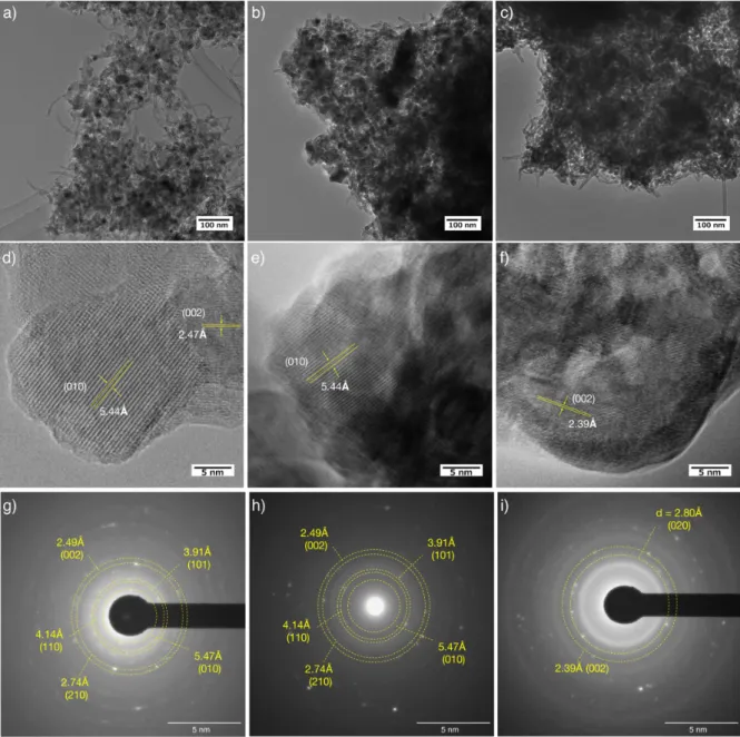
magnitude, matching the rate-capability improvement pre-viously reported.11Interestingly, transmission electron micros-copy investigation on activated and nonactivated samples shows that the morphology of the whole entity of the particle composites does not seem to be affected by the activation process (Figure S2a−c). The presence of clear lattice fringes observed for the pristine Li3VO4, nonactivated, and activated samples indicates that neither amorphization nor pulverization occurred during the activation process (Figure S2d−f). The only difference that can be observed is the fringes distances which change from 5.44 Å for pristine and nonactivated samples to 2.39 Å for activated one. This change confirms that the activation process is associated with a structure change which will be discussed in the following sections and used to explain the improvements in electrochemical characteristics.
The in situ XRD patterns recorded at the 1st, 2nd, and 20th cycles, the latter being representative of all other patterns collected over the last 10 cycles, are reported inFigure 2. For clarity, the lithiation of MWCNT occurring during the first stage of the lithiation process as detailed in Figure S1is not described and values stated for the quantity of lithium exchanged will always refer to the active oxide material. The comparison of the XRD patterns collected during the first lithiation (Figure 2a) confirms the typical evolution already
reported.11The reaction starts with the“Li3VO4-Phase A”
two-phase domain followed by the lithiation of two-phase A in a solid solution process as indicated by the progressive shift toward higher angles (low inter-reticular distances) of the Bragg peaks (Figure 2c). Further lithiation, below 0.7 V, of the as-obtained Li4VO4phase A leads to the formation of phase B in a
two-phase process as confirmed by the growing of a new set of
Bragg peaks and disappearance of the lithiated phase A one.11 During thefirst delithiation, the extraction of Li from phase B occurs via a two-phase domain as evidenced by the progressive disappearance of phase B XRD pattern and growing of a new set of Bragg peaks. The careful analysis of the XRD patterns shows that, during thefirst delithiation, the Bragg peaks shift toward high angles (low inter-reticular distances), in the same way as observed during the lithiation of phase A (see arrow in
Figure 2c). Moreover, during the lithiation at the second cycle, the examination of the XRD pattern shows that the Bragg peaks shift toward lower angle (higher inter-reticular distances), opposite to what is observed during the first lithiation of phase A. These findings suggest that, upon delithiation of phase B, a new phasedenoted phase C in the followingis formed, and that ultimately the material not only fails to revert to Li3VO4, as already reported, but also does not
return to phase A. In addition, the gradual disappearance of the pattern of phase A and the gradual growth of those corresponding to phases B and C (see highlighted angles domain inFigure 2a) show that these structure changes occur progressively during thefirst 10 cycles before reaching a stable configuration in which only phase C at high voltage and phase B at low voltage are involved. These results clearly demonstrate that the high electrochemical performance widely reported for β-Li3VO4is in fact related to the phase C−phase B system and
not to a hypothetical reversible solid solution of Li in pristine β-Li3VO4as proposed in previous reports.9,23,24
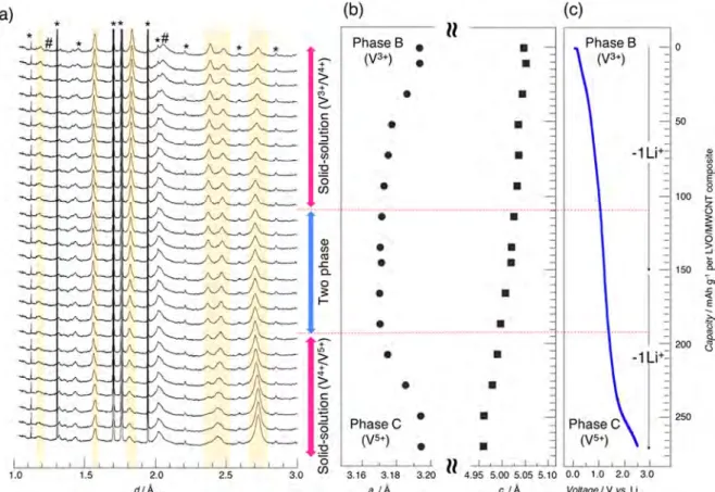
To obtain deeper insight into this system, we focus next on the stable electrochemical configuration reached after 20 cycles. To improve the resolution of the XRD data, synchrotron experiments have been carried out in operando Figure 3.(a) Synchrotron in operando XRD patterns for uc-Li3VO4/MWCNT (60/40) collected during the delithiation at 20 cycles (* in situ cell
over the course of 20 cycles. Regarding the evolution of the patterns showing the same behavior as detailed above, for sake of clarity, only the delithiation process collected during the 20th charge is shown inFigure 3a as a function of d-spacing. To get rid of side diffraction peaks or high background (due to electrochemical cells or electrolytes), ex situ synchrotron data have also been collected at both fully charged and discharged states (seeFigure S3). The comparison of the XRD patterns collected ex situ with the in operando ones shows no major difference, confirming that both phases B and C are stable. Unfortunately, in all casesand probably in conjunction with the drastic changes occurring during the activation process the quality of data prevent an accurate structure determination. Nevertheless, qualitative information can be obtained by the analysis of Bragg-peak locations which shows that patterns characteristic of phase C and phase B can both be indexed using the same hexagonal cell and highly symmetric space group P63/mmc (no. 194) as evidenced by the calculated XRD patterns (seeFigure S4). The refined cell parameters are a = 3.218 Å, c = 4.819 Å for fully charged phase C and a = 3.189 Å, c = 5.009 Å for discharged phase B. The comparison of these unit cells to that ofβ-Li3VO4(space group Pmn21: a = 6.326 Å,
b = 5.446 Å, and c = 4.947 Å) shows that they are linked by the relation aLVO= 2aH; bLVO= 2aHcos 30°; cLVO= cH(where the subscripts LVO and H corresponds toβ-Li3VO4and hexagonal
unit cells, respectively). This clearly indicates that the structures of phase C and phase B present the same hcp oxygen array as observed in pristineβ-Li3VO4. In addition, the
use of small primitive cell and high-symmetry space group compared to the supercell and low-symmetry space group needed to describe the ordering of the cations in pristine β-Li3VO4 (Figure S4) indicate that in both phases Li and V
cations are randomly distributed. This can be considered as evidence that the lithiation process induces a disordering of the cation distribution over the various accessible sites and suggests, as both phase B and C present such disordering, that the migration of the cations is responsible for the irreversibility observed during the activation process. Then the similarity of the XRD pattern of phase B and phase C as well as the low polarization observed in the electrochemical behavior observed once the activation process is achieved show that the insertion/extraction of lithium in/out phase C/phase B, respectively, should be associated with minor and reversible structure changes. This is confirmed by the evolution of the in operando synchrotron data collected during the delithiation at the 20th cycle (Figure 3a) which does not show a clear change in the set of Bragg peaks, suggesting a solid solution process. However, the evolution of the refined cell parameters reported inFigure 3b clearly shows that delithiation occurs in a three-stage process. It includes two solid-solution domains: one below 1.0 V vs Li (redox of V4+/V3+) and one beyond 1.4 V vs
Li (redox of V5+/V4+) as evidenced by the different evolutions
of the a cell parameter (decrease/increase), separated by a two-phase domain in the [1.4−1.0 V vs Li] voltage range corresponding to the switch between the V4+/V3+and V5+/V4+ active redox couples.
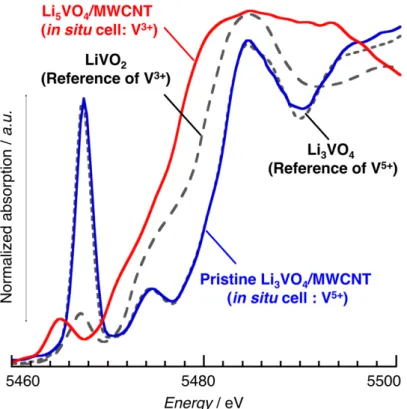
To obtain more information on the vanadium local environment and its evolution, we collected vanadium K-edge X-ray adsorption fine structure (XAFS) data in situ during thefirst cycle (activation process). The reversible and constant shift of the vanadium K-edge toward lower/higher energy values for lithiation/delithiation processes, respectively, confirms that vanadium is the active redox species over the entire domain and that the two redox couples V5+/V4+ and Figure 4. In situ XANES spectra recorded during lithiation (a) and delithiation (b) of a uc-Li3VO4/MWCNT sample at the 1st cycle and
corresponding charge−discharge curves (c). XANES spectra of lithiation (d) and delithiation (e) for the same uc-Li3VO4/MWCNT sample at the
V4+/V3+participate reversibly. The obtained pre-edge feature for the pristine Li3VO4/MWCNT and fully lithiated Li5VO4/ MWCNT well agree with that for the reference Li3VO4(V5+)
and LiVO2 (V3+), respectively (see Figure S5). The
examination of the evolution of the K-edge pre-edge peak (Figure 4a) shows that a drastic change of the oxygenated environment of the vanadium occurs during cycling. Starting with a sharp intense peak characteristic of V in tetrahedral (Td) sites, as observed in pristine Li3VO4, the lithiation
induces a decrease in intensity and a splitting/broadening of the pre-edge peak characteristic of more or less distorted trigonal bipyramid (TbP) or octahedral site (Oh).25 This evolution is in perfect agreement with the need to define suitable oxygenated environments for reduced-valence states of vanadium, which cannot be stabilized in purely Td sites as can V5+. During the delithiation at thefirst cycle (Figure 4b), the shape of the vanadium K-edge pre-edge peak switches back from low-intensity and split/broad peak to high-intensity and single peak in a reversible way, which seems to contradict the irreversible structure changes identified in both diffraction and electrochemical behavior. In that case, it is speculated that, instead of a real migration of vanadium cations back to pure symmetric Td sites, a shift out of the center of the TbP or Oh site toward two oxygen ions occurs to allow the formation of the short vanadyl VO bonds characteristic of V5+ valence
state. This is in perfect agreement with several reported vanadium-based structures in which the V5+ lies in distorted
octahedral or TbP sites exhibiting also a sharp and intense pre-edge peak.25,26The examination of the evolution of the pre-edge peaks after the completion of the activation (at 20th cycle, Figure 4d,e) shows a reversible change from a sharp intense peak for charged phase C to a broadened, low-intensity peak for discharged phase B without extra changes in perfect agreement with an accommodation of the change in the V valence state occurring without drastic modification of the oxygenated environment.
On the basis of the identification of plausible structure changes deduced from both XANES (local ordering) and XRD (long-range ordering) data, a tentative structure refinement was conducted using synchrotron data collected ex situ. However, as already described, the low quality of the data, inherent to the wide structure changes and to the need of 20 cycles to reach stable configuration, prevent a full structure
determination and limit expected results of the structure refinement. For these reasons we decided to conduct the refinement using the most symmetric unit cell (ZnS-wurtzite type) to restrict as much as possible the number of parameters that can be refined and to allow taking into account the cation mixing obviously operating. As XANES studies show a drastic change of the vanadium oxygenated environment during the activation process and suggest smooth distortions once the stable configuration is reached, the refinement of phases B and C have been conducted, considering as a starting model that the vanadium is equally distributed in Td and Oh sites of the ZnS-structure type. The z coordinate of both V and O and the occupancy factor of the different V sites are refined while maintaining a ratio V/O = 1. In both cases (Figure S6) the evolution of the z coordinate shows a shift of the V initially located in the Td environment toward one triangular base, implying consideration of a fifth V−O bond indicating the formation of a TbP environment. The refinement of the V sites occupancy shows that, in charged phase C, the V appears mainly located in TbP sites, and that in the fully lithiated phase B, additional Oh sites have to be considered. Even if the refinements lead only to average structures, the combination of all experimental data agree to describe the structure of phases C and B as built up with the same hcp array of oxygen and to consider that vanadium cations are randomly distributed over TbP and/or Oh sites with a preference for the latter for fully discharged phase B. In addition, the small, highly symmetric unit cell observed for phases B and C also shows that the migration of vanadium from Td to TbP or Oh sites breaks the ordered character of the pristine Li3VO4and indicates that it should be associated with a Li,V cation mixing. This migration, although often observed during electrochemical processes at room temperature, implies the breaking and rebuilding of bonds between metal and oxygen. This should be responsible for kinetic limitations in perfect agreement with the electro-chemical behavior reported for the activation process of Li3VO411and the need for at least 10 cycles to achieve the full transformation. This phenomenon of full cation mixing associated with low kinetics occurring progressively along several cycles is not new and has already been observed to occur for other ordered Li3PO4 structure-type compounds such as Li2FeSiO4.27 In the latter case, the electrochemical
lithiation leads to a cation mixing between Li and Fewith Si Figure 5.Overall redox mechanism of Li3VO4without (left) and with (right) activation process. Without activation, the accommodation of the
reversible 5+/4+ vanadium valence state is ensured by a shift out of the center of the Td environment. With activation the reduction down to V3+
remaining located in its original sitesand operates progressively along the first 20 cycles, inducing, as observed for β-Li3VO4, a progressive narrowing of the voltage profile.
The different behaviors between Li/Fe on the one hand and Si on the other hand are related to the strong covalent character of Si−O bonds compared to that of Li−O and Fe−O bonds. The small difference between the iono-covalency of the Li−O and V3+−O bonds and between the ionic radii of Li+(0.76 Å)
and V3+ (0.64 Å)28 should explain that, in this case, a full cation mixing can be achieved.
As the different phases involved in the lithiation of Li3VO4
exhibit the same hcp anionic network, the evolution can be understood by considering changes in site occupancy, allowing the rationalization of the different structure evolutions. In structures built up using a close-packed anionic network, the number of Oh and Td sites are respectively equal to and twice the number of oxygen building the network. In hcp-derived structures, Td sites and Oh sites share faces, implying that, for stability reasons, only half of each type of site can be occupied, as observed in the pristineβ-Li3VO4 structure, which can be formulated as [Li3V1□4]Td[□4]OhO4(□ stands for vacancies,
Td tetrahedral, and Oh octahedral) as shown inFigure 5. The lithiation process induces the progressive migration of vanadium ions into the Oh sites, characteristic of the fully lithiated phase B, together with the insertion of two extra Li. Considering the maximal half-occupancy of Td sites and results from XAFS measurements showing V essentially located in Oh environment, this implies that some of the lithium ions should also be located in Oh sites, driving to formulate the phase B as [Li4Vδ□4−δ]TbP[V1−δLi1□2+δ]OhO4with respect to
both TbP and Oh occupancy limits. Interestingly, this lithiated phase B (Li5VO4) can be rewritten as Li2[(Li1/2V1/2)]O2, and
then be interpreted as a Li-rich homologue of Li2VO2
([Li4□4]Td[V2□2]OhO4)16 which also adopt a hcp-based structure. As the occupied Td sites share edges, one may expect that to minimize repulsive effects, only the Li located in these sites will participate in electrochemical processes in agreement with what is observed during the charge of Li2VO2. XRD refinement shows that, in phase C, the vanadium lies also in the TbP environment itself deriving from the Td one so that a partial migration of the vanadium back to the distorted TbP site cannot be totally ruled out. Then the delithiated phase C can be formulated as [Li2V1−δ□5+δ]TbP[VδLi1□3−δ]OhO4 and compared to the homologous charged Li1−x[LixV1−x]O2
layered compound ([Li2□6]Td[V2□2]OhO4). The presence of
some V ions in the Li layer can induce the pillaring of the structure and could explain why the delithiation of phase B preserves the disordered hcp-type structure, while the delithiation of Li2VO2 induces a drastic structure change to
recover the Li1−x[LixV1−x]O2ordered fcc-type structure. These differences can explain why, despite being close in terms of structure, activated phase B Li5VO4 and Li2VO2 present
different electrochemical performances. The stability of the hcp network over the whole electrochemical process results in better reversibility for phase C−phase B process, as confirmed by the long cycling stability over 2000 cycles12,19compared to the one reported for LiVO2(<50 cycles).16,29−33In addition, the exchange of two Li per V in Li3VO4 unit leads to a
reversible capacity of 394 mA h g−1, which is 25% higher than that reported for the exchange of only one Li per V in LiVO2
(295 mA h g−1). The two V5+/V4+and V4+/V3+redox couples operate, of course, at a higher voltage than that reported for V3+/V2+, with, however, lower polarization and an average
operating voltage close to 1 V vs Li intermediate between the 0.2 V vs Li reported for Li2VO216and 1.6 V vs Li reported for
the best titanium-based negative electrodes.34,35Finally, phase C can be obtained by the electrochemical activation process of β-Li3VO4itself easy to be synthesized, with no need for the
delicate balance of unstable vanadium valence states required to obtain the electrochemically active Li1+xV1−xO2 phase.16,18 In addition to all of these advantages, the investigation of the active phase C↔ phase B reversible mechanism shows, for the first time for hcp-based compounds, that electrochemical lithiation/delithiation mechanisms can lead to cation mixing without degraded electrochemical performance, as was recently reported for some conventional fcc-based LiMO2 layered compounds.36,37 Moreover, the cation-mixing operation in hcp-based compounds not only avoids the performances degradation reported for fcc-derived structures but also yields a large improvement in the lithium diffusion coefficient.
■
CONCLUSIONSThe detailed understanding of the complex mechanism occurring during the lithiation of Li3VO4 suggests new
possibilities for ion migration and cation mixing in hcp-based compounds with an enhancement of electrochemical perform-ances and the potential to intake 2 times more lithium per V than fcc-based homologue. In addition, as covalent bonding is well-known to stabilize hcp-type rather than fcc-type networks, this study opens the way to the design of new polyanionic compounds with a cation-disordered structure, thus allowing a fine-tuning of working voltages and broadening the range of possibilities to include both negative- and positive-electrode materials.
■
ASSOCIATED CONTENT*
S Supporting InformationThe Supporting Information is available free of charge on the
ACS Publications website at DOI: 10.1021/acs.chemma-ter.8b00721.
Additional experimental data: electrochemical measure-ments, ex situ XRD, and in situ XAFS (PDF)
■
AUTHOR INFORMATION Corresponding Authors *E-mail:[email protected]. *E-mail:[email protected]. ORCID Patrice Simon:0000-0002-0461-8268 Katsuhiko Naoi:0000-0002-0265-2235 NotesThe authors declare no competingfinancial interest.
■
ACKNOWLEDGMENTSThis study was supported by the Global Innovation Research Organization in TUAT, JSPS Grant-in-Aid for Scientific Research (KAKENHI) A under Grant No. JP25249140, KAKENHI C under Grant No. JP17K05962, KAKENHI Grand-in-Aid for Young Scientists B under Grant No. JP16K17970, and the Center of Innovation Program from Japan Science and Technology Agency (A-STEP; AS282S002d). The synchrotron radiation experiments were performed at the BL14B2 of SPring-8 with the approval of the Japan Synchrotron Radiation Research Institute (JASRI)
(Proposal No. 2016B1544) and at the BL8S1 of the Aichi Synchrotron Radiation Center (Aichi, Japan) (Proposal No. 201606105).
■
REFERENCES(1) Salanne, M.; Rotenberg, B.; Naoi, K.; Kaneko, K.; Taberna, P. L.; Grey, C. P.; Dunn, B.; Simon, P. Efficient storage mechanisms for building better supercapacitors. Nat. Energy 2016, 1, 16070.
(2) Augustyn, V.; Simon, P.; Dunn, B. Pseudocapacitive oxide materials for high-rate electrochemical energy storage. Energy Environ. Sci. 2014, 7 (5), 1597−1614.
(3) Zhao, E.; Qin, C.; Jung, H.-R.; Berdichevsky, G.; Nese, A.; Marder, S.; Yushin, G. Lithium Titanate Confined in Carbon Nanopores for Asymmetric Supercapacitors. ACS Nano 2016, 10 (4), 3977−3984.
(4) Augustyn, V.; Come, J.; Lowe, M. A.; Kim, J. W.; Taberna, P.-L.; Tolbert, S. H.; Abruña, H. D.; Simon, P.; Dunn, B. High-rate electrochemical energy storage through Li+intercalation
pseudocapa-citance. Nat. Mater. 2013, 12 (6), 518−522.
(5) Li, J.; Tang, Z.; Zhang, Z. Layered Hydrogen Titanate Nanowires with Novel Lithium Intercalation Properties. Chem. Mater. 2005, 17 (23), 5848−5855.
(6) Naoi, K.; Kurita, T.; Abe, M.; Furuhashi, T.; Abe, Y.; Okazaki, K.; Miyamoto, J.; Iwama, E.; Aoyagi, S.; Naoi, W.; Simon, P. Ultrafast Nanocrystalline-TiO2(B)/Carbon Nanotube Hyperdispersion
Pre-pared via Combined Ultracentrifugation and Hydrothermal Treat-ments for Hybrid Supercapacitors. Adv. Mater. 2016, 28 (31), 6751− 6757.
(7) Ogihara, N.; Yasuda, T.; Kishida, Y.; Ohsuna, T.; Miyamoto, K.; Ohba, N. Organic Dicarboxylate Negative Electrode Materials with Remarkably Small Strain for High-Voltage Bipolar Batteries. Angew. Chem. 2014, 126 (43), 11651−11656.
(8) Oki, H.; Takagi, H. Y2Ti2O5S2 as a high performance anode
material for Li ion batteries. Solid State Ionics 2015, 276, 80−83. (9) Li, H. Q.; Liu, X. Z.; Zhai, T. Y.; Li, D.; Zhou, H. S. Li3VO4: A
Promising Insertion Anode Material for Lithium-Ion Batteries. Adv. Energy Mater. 2013, 3 (4), 428−432.
(10) Wei, H. Y.; Tsai, D. S.; Hsieh, C. L. A prelithiated lithium vanadate anode and the mass balancing of its hybrid capacitor. RSC Adv. 2015, 5 (85), 69176−69183.
(11) Iwama, E.; Kawabata, N.; Nishio, N.; Kisu, K.; Miyamoto, J.; Naoi, W.; Rozier, P.; Simon, P.; Naoi, K. Enhanced Electrochemical Performance of Ultracentrifugation-Derived nc-Li3VO4/MWCNT
Composites for Hybrid Supercapacitors. ACS Nano 2016, 10 (5), 5398−5404.
(12) Shen, L.; Lv, H.; Chen, S.; Kopold, P.; van Aken, P. A.; Wu, X.; Maier, J.; Yu, Y. Peapod-like Li3VO4/N-Doped Carbon Nanowires
with Pseudocapacitive Properties as Advanced Materials for High-Energy Lithium-Ion Capacitors. Adv. Mater. 2017, 29, 1700142.
(13) Dong, B.; Jarkaneh, R.; Hull, S.; Reeves-McLaren, N.; Biendicho, J. J.; West, A. R. Synthesis, structure and electrical properties of N-doped Li3VO4. J. Mater. Chem. A 2016, 4 (4), 1408−
1413.
(14) Padhi, A. K.; Manivannan, V.; Goodenough, J. B. Tuning the Position of the Redox Couples in Materials with NASICON Structure by Anionic Substitution. J. Electrochem. Soc. 1998, 145 (5), 1518− 1520.
(15) Cao, A.-M.; Hu, J.-S.; Liang, H.-P.; Wan, L.-J. Self-Assembled Vanadium Pentoxide (V2O5) Hollow Microspheres from Nanorods
and Their Application in Lithium-Ion Batteries. Angew. Chem., Int. Ed. 2005, 44 (28), 4391−4395.
(16) Armstrong, A. R.; Lyness, C.; Panchmatia, P. M.; Islam, M. S.; Bruce, P. G. The lithium intercalation process in the low-voltage lithium battery anode Li1+xV1−xO2. Nat. Mater. 2011, 10 (3), 223−
229.
(17) Pourpoint, F.; Hua, X.; Middlemiss, D. S.; Adamson, P.; Wang, D.; Bruce, P. G.; Grey, C. P. New Insights into the Crystal and Electronic Structures of Li1+xV1−xO2 from Solid State NMR, Pair
Distribution Function Analyses, and First Principles Calculations. Chem. Mater. 2012, 24 (15), 2880−2893.
(18) Gędziorowski, B.; Kondracki, Ł.; Świerczek, K.; Molenda, J. Structural and transport properties of Li1+xV1−xO2anode materials for
Li-ion batteries. Solid State Ionics 2014, 262, 124−127.
(19) Li, Q. D.; Sheng, J. Z.; Wei, Q. L.; An, Q. Y.; Wei, X. J.; Zhang, P. F.; Mai, L. Q. A unique hollow Li3VO4/carbon nanotube
composite anode for high rate long-life lithium-ion batteries. Nanoscale 2014, 6 (19), 11072−11077.
(20) Yang, Y.; Li, J. Q.; He, X. Y.; Wang, J.; Sun, D.; Zhao, J. B. A facile spray drying route for mesoporous Li3VO4/C hollow spheres as
an anode for long life lithium ion batteries. J. Mater. Chem. A 2016, 4 (19), 7165−7168.
(21) Shen, L.; Chen, S.; Maier, J.; Yu, Y. Carbon-Coated Li3VO4
Spheres as Constituents of an Advanced Anode Material for High-Rate Long-Life Lithium-Ion Batteries. Adv. Mater. 2017, 29 (33), 1701571.
(22) Iwama, E.; Simon, P.; Naoi, K. Ultracentrifugation: An effective novel route to ultrafast nanomaterials for hybrid supercapacitors. Curr. Opin. Electrochem. 2017, 6 (1), 120−126.
(23) Liang, Z. Y.; Lin, Z. P.; Zhao, Y. M.; Dong, Y. Z.; Kuang, Q.; Lin, X. H.; Liu, X. D.; Yan, D. L. New understanding of Li3VO4/C as
potential anode for Li-ion batteries: Preparation, structure character-ization and lithium insertion mechanism. J. Power Sources 2015, 274, 345−354.
(24) Liao, C.; Zhang, Q.; Zhai, T.; Li, H.; Zhou, H. Development and perspective of the insertion anode Li3VO4 for lithium-ion
batteries. Energy Storage Materials 2017, 7, 17−31.
(25) Yamamoto, T. Assignment of pre-edge peaks in K-edge x-ray absorption spectra of 3d transition metal compounds: electric dipole or quadrupole? X-Ray Spectrom. 2008, 37 (6), 572−584.
(26) Wong, J.; Lytle, F. W.; Messmer, R. P.; Maylotte, D. H. K-edge absorption spectra of selected vanadium. Phys. Rev. B: Condens. Matter Mater. Phys. 1984, 30 (10), 5596−5610.
(27) Nytén, A.; Abouimrane, A.; Armand, M.; Gustafsson, T.; Thomas, J. O. Electrochemical performance of Li2FeSiO4as a new
Li-battery cathode material. Electrochem. Commun. 2005, 7 (2), 156− 160.
(28) Shannon, R. Revised effective ionic radii and systematic studies of interatomic distances in halides and chalcogenides. Acta Crystallogr., Sect. A: Cryst. Phys., Diffr., Theor. Gen. Crystallogr. 1976, 32 (5), 751−767.
(29) Choi, N.-S.; Kim, J.-S.; Yin, R.-Z.; Kim, S.-S. Electrochemical properties of lithium vanadium oxide as an anode material for lithium-ion battery. Mater. Chem. Phys. 2009, 116 (2), 603−606.
(30) Song, J. H.; Park, H. J.; Kim, K. J.; Jo, Y. N.; Kim, J.-S.; Jeong, Y. U.; Kim, Y. J. Electrochemical characteristics of lithium vanadate, Li1+xVO2, new anode materials for lithium ion batteries. J. Power
Sources 2010, 195 (18), 6157−6161.
(31) Kim, W.-T.; Jeong, Y. U.; Choi, H. C.; Kim, Y. J.; Song, J. H.; Lee, H.; Lee, Y. J. New anode materials of Li1+xV1−xO2(0≤ x ≤ 0.1)
for secondary lithium batteries: correlation between structures and properties. J. Appl. Electrochem. 2011, 41 (7), 803.
(32) Ahn, J.; Oh, S. H.; Kim, J. H.; Cho, B. W.; Kim, H. S. The effect of vanadium precursors on the electrochemical performance of Li1.1V0.9O2as an anode material for Li-ion batteries. J. Electroceram.
2014, 32 (4), 390−395.
(33) Kim, W.-T.; Jeong, Y. U.; Choi, H. C.; Lee, Y. J.; Kim, Y. J.; Song, J. H. Structures and electrochemical properties of Li1.075V0.925−xMxO2 (M = Cr or Fe, 0 ≤ x ≤ 0.025) as new anode
materials for secondary lithium batteries. J. Power Sources 2013, 221, 366−371.
(34) Wang, S.; Quan, W.; Zhu, Z.; Yang, Y.; Liu, Q.; Ren, Y.; Zhang, X.; Xu, R.; Hong, Y.; Zhang, Z.; Amine, K.; Tang, Z.; Lu, J.; Li, J. Lithium titanate hydrates with superfast and stable cycling in lithium ion batteries. Nat. Commun. 2017, 8 (1), 627.
(35) Dylla, A. G.; Henkelman, G.; Stevenson, K. J. Lithium Insertion in Nanostructured TiO2(B) Architectures. Acc. Chem. Res. 2013, 46
(36) Yabuuchi, N.; Nakayama, M.; Takeuchi, M.; Komaba, S.; Hashimoto, Y.; Mukai, T.; Shiiba, H.; Sato, K.; Kobayashi, Y.; Nakao, A.; Yonemura, M.; Yamanaka, K.; Mitsuhara, K.; Ohta, T. Origin of stabilization and destabilization in solid-state redox reaction of oxide ions for lithium-ion batteries. Nat. Commun. 2016, 7, 13814.
(37) Lee, J.; Urban, A.; Li, X.; Su, D.; Hautier, G.; Ceder, G. Unlocking the Potential of Cation-Disordered Oxides for Recharge-able Lithium Batteries. Science 2014, 343 (6170), 519.
1
Supporting Information
Cation-Disordered Li
3VO
4: Reversible Li-Insertion/Deinsertion Mechanism for Quasi
Li-rich Layered Li
1+x[V
1/2Li
1/2]O
2(x=0-1)
Patrick ROZIER,
1,2,3Etsuro IWAMA,
*1,4Nagare NISHIO,
4Kazuhisa BABA,
4Keisuke
MATSUMURA,
4Kazuaki KISU,
1,4Junichi MIYAMOTO,
1,5,6Wako NAOI,
6Yuki
ORIKASA,
7Patrice SIMON,
1,2,3and Katsuhiko NAOI*
1,4,51
Insitute of Global Innovation Research Organization, Tokyo University of Agriculture &
Technology, 2-24-16 Naka-cho, Koganei, Tokyo 184-8558, Japan
2
CIRIMAT, Université de Toulouse, CNRS, Université Toulouse 3 - Paul Sabatier, 118
Route de Narbonne, 31062 Toulouse cedex 9 - France.
3
Réseau sur le Stockage Electrochimique de l’Energie, RS2E FR CNRS 3459
4
Department of Applied Chemistry, Tokyo University of Agriculture & Technology, 2-24-16
Naka-cho, Koganei, Tokyo 184-8558, Japan
5
Advanced Capacitor Research Center, Tokyo University of Agriculture & Technology,
2-24-16 Naka-cho, Koganei, Tokyo 184-8558, Japan
6
Division of Art and Innovative Technologies, K & W Inc, 1-3-16-901 Higashi, Kunitachi,
Tokyo 186-0002, Japan
7
Department of Applied Chemistry, College of Life Sciences, Ritsumeikan University, 1-1-1
Noji-higashi, Kusatsu, Shiga 525-8577 Japan
*E-mail: [email protected] / [email protected]
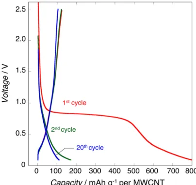
Electrochemical behavior of MWCNTs:
Charge discharge tests were conducted on the MWCNT treated by ultracentrifugation
process
1(MWCNT) to assess the electrochemical contribution of MWCNTs in the
uc-Li
3VO
4/MWCNT (60/40 in weight) composites. The electrochemical test cell was assembled,
using an uc-MWCNT powder (cathode), a lithium metal (anode), 1 M LiPF
6in EC +DEC
(50:50 in volume ratio) (electrolyte, Kishida Chemicals (water content < 50 ppm)), and 1
layer of 420 µm-thick glass fiber (separator, Nippon Kodoshi). Measurements were conducted
at constant current mode with 0.04 A g
-1from 0.1 to 2.5 V vs. Li. As shown in Figure S1,
uc-MWCNTs show clear plateau during the first lithiation starting from ca. 0.9 V vs. Li, which
can be also seen in the first lithiation shown in Figure 1a of the main manuscript. This plateau
is irreversible and completely disappears at the second cycle, leading to an irreversible
2
within the range of 600-670 mAh g
-1at different tests, giving ca. ±10% of error value from
theoretical capacity (394 mAh g
-1) when the capacity contribution of Li
3
VO
4is estimated by
subtraction of MWCNT capacity from the whole composite capacity. However, the
irreversible capacity drastically decreased to few 10 mAh g
-1at the 2
ndcycle, and became
negligible at 20
thcycle with stable charge discharge cycling. In the end, the reversible
capacity at the 20
thcycle is 100 mAh g
-1, which accounts for 14.5% of the total capacity for
the uc-Li
3VO
4/MWCNT (60/40 in weight) composite.
Figure S1. Charge / discharge curves at 0.04 A g
-1for uc-MWCNT during 1
st(red), 2
nd(green), and 20
th(blue) cycles. The cell contains 10 mg of MWCNT powder (cathode) and a
Li metal (anode). One layer of 420 µm-thick glass fiber separator (Nippon Kodoshi) was used
as a separator. The voltage was set from 0.1 V to 2.5 V vs Li after the initial lithiation.
TEM image comparisons among pristine, nonactivated, and activated Li
3VO
4/MWCNT
composites:
To clarify the effect of the electrochemical activation both on the particle/composite
morphologies and crystallinity of Li
3VO
4, we observed three different samples; pristine
3
conditioning to obtain activated/nonactivated samples is as written in the experimental section
of main text. As shown in Figure S2 (a)-(c), the “morphology” of the whole entity of the
particle composites has not essentially changed before(b) and after(c) activation. Regarding,
however, on the change in “crystallinity” of the samples before and after activation, we made
a closer look at the magnified TEM images especially on the lattices and their alignments.
Clear lattice fringes can be observed for the pristine as well as the samples before and after
electrochemical treatment shown in Figure S2 (d)-(f).
Figure S2 TEM images focused on composite morphology (a)-(c) and crystalline lattice
(d)-(f) and ED patterns (g)-(i) for different three samples; pristine Li
3VO
4/MWCNT (a), (d), (g),
nonactivated Li
3VO
4/MWCNT (b), (e), (h), and activated Li
3VO
4/MWCNT (c), (f), (i);
4
This is a clear evidence that indicates neither amorphization nor pulverization occurred during
the activation process. However, the activation process brought about the changes in observed
fringe distances from 5.44 to 2.39 Å. Such changes are well consistent with the corresponding
XRD shown in Figure S3 and ED patterns for the same samples shown below [Figure
S2(g)-(i)].
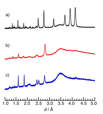
Synchrotron X-ray diffraction measurements (powder, ex situ):
In order to confirm the validity of the X-ray diffraction (XRD) patterns obtained by in
situ and in operando measurements, synchrotron ex situ (powder) XRD measurements were
performed on three different powder samples (pristine ultracentrifugation (uc)-treated
Li
3VO
4/multi-walled carbon nanotube composite (uc-Li
3VO
4/MWCNT, V
5+)
1, phase C (V
5+),
and phase B (V
3+)). The XRD patterns were collected at two different synchrotron facilities; i)
XRD patterns of uc-Li
3VO
4/MWCNT and phase B were collected at the beam line BL5S2 of
Aichi Synchrotron Radiation Center (Aichi, Japan) (x-ray radiation λ = 0.70033 Å, operating
at 45 kV - 200 mA), and ii) the XRD pattern for the phase C was collected at the beam line
BL19B2 of Spring 8 (Hyogo, Japan) for phase C (x-ray radiation λ = 0.69997 Å, operating at
45 kV - 200 mA). Prior to the XRD measurements, lithium half cells composed of Li/1 M
LiPF
6in ethylene carbonate (EC) and diethyl carbonate (DEC) (1:1 in
vol%)/uc-Li
3VO
4/MWCNT were assembled inside of Ar-filled glove box and cycled for 20 cycles
within in the voltage range between 0.1 and 2.5 V vs. Li. The samples were then collected
washed by DEC several times and dried under vacuum overnight before putting them into the
thin-walled Lindemann glass capillary (f = 0.5 mm) and sealing the capillaries in the glove
box. The obtained three XRD patterns plotted against d space are shown in Figure S3. The
disappearance of the main four peaks at large d value over 3.0 Å and the simplification of the
overall XRD patterns can be seen in XRD patterns of phase C and phase B (Figure S3b and c),
compared to the pristine uc-Li
3VO
4XRD pattern (Figure S3a). Such results are consistent
5
with the results obtained by in situ and in operando XRD measurements shown in Figure 2
and 3 in the main manuscript, suggesting the both phases are stable, which is different from
the metastable phase of phase A
1.
Figure S3. Synchrotron ex situ powder XRD for the (a) pristine uc-LVO/MWCNT (60/40)
composites (black), (b) phase C (red), and (c) phase B (blue).
Comparison of calculated XRD patterns for Li
3VO
4with different site occupancy:
To support our proposition of the crystal structures of phase B and C, we calculated
different XRD patterns considering several hypothesis for the location of Li and V as shown
in Figure S4. By a full Li/V mixing of the pristine Li
3VO
4, yellow-highlighted regions of
Bragg peaks corresponding to the 2
q
< 30˚ disappears due to the averaging of the structure
[Figure S4(a) and (b)]. Such disappearance in Bragg peaks can be observed even by changing
Td site of the Li
3VO
4crystal structure into ZnS type [Figure S4(c)]. Considering then the
well-known relationship between the valence state of vanadium and its coordination number,
the lithiation of Li
3VO
4(V
5+in Td with coordination number (CN) = 4) cannot proceed
6
without a change of the V oxygenated surrounding. Thus, XRD patterns with two different V
coordination structures, a trigonal bipyramid (TbP, CN = 5) and octahedral (Oh, CN = 6),
were calculated using symmetric ZnS-W type structure in order to determine the most
plausible Li/V migration. Here, the TbP coordination can be obtained by a small shift of
vanadium from the center of the Td site toward the center of the triangular plane, while a
more drastic change occurs by the migration of the vanadium toward the center of the Oh
surrounding. The intensity of Bragg peaks at 2
q
= 38˚ and 50˚ clearly increases by change
from TbP to Oh, as shown in Figure S4(d) and (e) highlighted in green. These simulated
patterns are in good agreement with experimental pattern shown in Figure S4 [right] except
peaks preferentially oriented (see highlighted area in red), which is clearly seen even for the
pristine Li
3VO
4.
Figure S4 [Left] (a)-(e) calculated XRD patterns for Li
3VO
4with different site occupancy.
[Right] Experimental XRD patterns of pristine Li
3VO
4, phase C, and phase B. The diffraction
angles were recalculated in lCuKa for the easy comparison.
In situ X-ray absorption fine structure (XANES) with reference data:
For the validation of pre-edge peak intensity in obtained in situ XAFS spectra, we
chose Li
3VO
4and LiVO
2as a reference of V
5+and V
3+, respectively. As shown in Figure S5,
Spectra for the pristine Li
3VO
4/MWCNT (blue) is well overlapped with that for the reference
a) Li3VO4 b) Li3VO4disordered c) ZnS-type V in Td d) ZnS-type V in TbP e) ZnS-type V in Oh 2θ / ˚ 10 20 30 40 50 60 70 80 Li3VO4 Phase C Phase B 2θ / ˚ 10 20 30 40 50 60 70 80 90
![Figure 1 a shows the cycling plots collected in the [2.5 −0.1 V] voltage range during the first 20 cycles for the Li 3 VO 4 / multiwalled carbon nanotube (LVO/MWCNT) nanocompo-site prepared via ultracentrifugation process](https://thumb-eu.123doks.com/thumbv2/123doknet/2975120.82995/4.938.222.712.99.546/figure-collected-multiwalled-nanotube-nanocompo-prepared-ultracentrifugation-process.webp)
![Figure S4 [Left] (a)-(e) calculated XRD patterns for Li 3 VO 4 with different site occupancy](https://thumb-eu.123doks.com/thumbv2/123doknet/2975120.82995/16.892.125.785.574.821/figure-left-calculated-xrd-patterns-different-site-occupancy.webp)
![Figure S6. [Left] Refinement results of XRD patterns, and [Right] tabulated parameters of](https://thumb-eu.123doks.com/thumbv2/123doknet/2975120.82995/18.892.165.718.680.1070/figure-left-refinement-results-patterns-right-tabulated-parameters.webp)
![Cation-Disordered Li3VO4: Reversible Li Insertion/Deinsertion Mechanism for Quasi Li-Rich Layered Li1+x[V1/2Li1/2]O2 (x = 0–1)](data:image/gif;base64,R0lGODlhAQABAIAAAP///wAAACH5BAEAAAAALAAAAAABAAEAAAICRAEAOw==)