an author's https://oatao.univ-toulouse.fr/25158
Bigand, Audrey and Espinosa, Christine and Bauchire, Jean-Marc and Flourens, Franck and Lachaud, Frédéric Lightning damage assessment into composite based on surface explosion and fiber breakage. (2019) In: 22nd International Conference On Composite Materials (ICCM22), 11 August 2019 - 16 August 2019 (Merlbourne, Australia).
LIGHTNING DAMAGE ASSESSMENT INTO COMPOSITE BASED ON
SURFACE EXPLOSION AND FIBER BREAKAGE
A. Bigand1,2,3, C. Espinosa1, J.M. Bauchire3, F. Flourens2, F. Lachaud1
1
Clément Ader ICA, Université de Toulouse, ISAE-SUPAERO, IMT MINES ALBI, UTIII, INSA, CNRS, 3 Rue Caroline Aigle, 31400 Toulouse, France
http://institut-clement-ader.org/
2
Airbus Operations SAS, 316 route de Bayonne, 31060 Toulouse Cedex 9, France
3GREMI, Université d’Orléans, 14 Rue d’Issoudun, 45067 Orléans, France
Keywords: lightning, damage, carbon fiber reinforced plastics, numerical simulations, phase change
ABSTRACT
Lightning damage mechanism for composite aircraft structure is a complex multi-physical phenomenon. The lightning current entering into the surface metallic protection and the carbon plies generates Joule’s effects and electromagnetic forces which both induce mechanical forces and surface explosion that produce a significant mechanical impact. The explosion of the lightning strike protection has been recorded through the measurement of the vaporization profile evolution in space and time using transparent glass epoxy substrates. In this paper, this profile is combined to shock wave model developed by the study of electric explosion on wire equivalent to web of ECF. The second important phenomenon is fiber breakage due to current flow in CFRP. This has been assessed through specific lightning test measuring the current distribution between CFRP and LSP depending on the paint thickness. It is aimed is this paper to present the tests setup and observations.
Those two loading components have been injected into a mechanical model using Abaqus Explicit® in order to assess the damage ignition and propagation in the composite thickness as a function of time. Simulations are similar to previous studies but use real tests measurements for the pressure evolution instead of an impulsion induced estimation. Results of the simulations are confronted with laboratory lightning tests. Deflection as functions of time has been measured thanks to stereo correlation devices. Simulated damage distributions are compared to post-mortem non-destructive and non-destructive measurement in the core of the composite plates.
1 INTRODUCTION
It is today difficult to predict the damage that could be generated by a lightning strike on a composite structure due to its complex phenomenology and the different forces involved [1]. The arc itself generates mechanical force as an acoustic shock wave and thermal constraints as a thermal flux transferred to the panel and thermal radiation from the arc. In addition, the lightning current of 100kA reached in about 20µs flowing into the structure (both lightning metallic protection and composite laminate) generates magnetic force (Laplace force) and Joule’s effect. The different forces are illustrated in Figure 1:
This latest phenomenon leads to a quick elevation of temperature of the LSP up to an explosion phase. The arc constriction due to the presence of a thick paint layer changes the current injection into the LSP and can lead to current injection into the first plies of CFRP (Carbon Fiber Reinforced Plastic) that will explode due to Joule’s effect. The paint is ejected lately due to the gas expansion thus has enhanced the overpressure generated on the surface as presented in Figure 2:
Figure 2 Lightning explosion
This will lead to important delamination into the composite structure in addition to the thermal damage which is important to predict aircraft structure safety. Most of the works have been focused on the damage generated by a thermal process on bare CFRP panel [2-6], but the reality of the use of CFRP in an aeronautical context is very different. The complexity of this phenomenon is enhanced by the fact that the damage is not only dependent on the structure configuration but also on the lightning strike protection and the paint thickness which are not part of the sizing of the composite structure against “nominal” stress loads. Indeed, those two parameters are of major importance in the surface explosion generation [7]. A continuous metallic protection like SCF (Solid Copper Foil) will prevent any damage to the composite structure as a shield but usual LSP like ECF (Expanded Copper Foil) is not efficient enough when combined with thick paint configuration.
Figure 3 Lightning Strike Protection principle
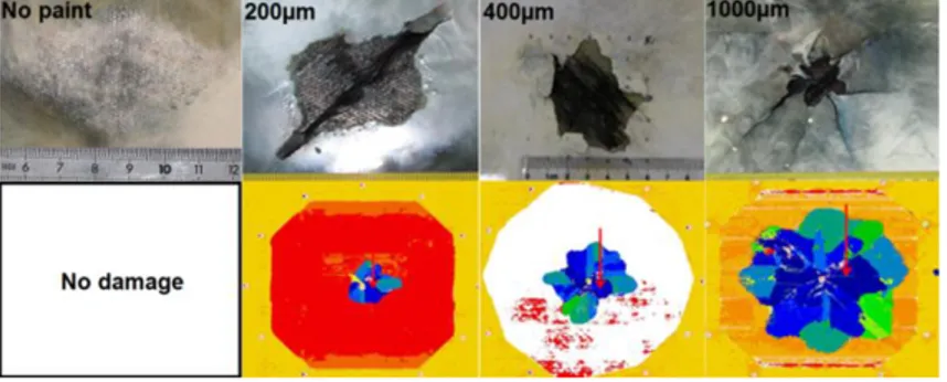
For an identical structure and ECF, the increase of paint leads to a significant increase of damage as it increases the overpressure generated on the surface by its confining effect and the amount of current flowing into the CFRP. Figure 4 presents the damage evolution with paint thickness. On the top line, you can see the closest view of the visual damage and on the bottom line, the structural damage on the same scale (Panel in the circular frame Ø370mm).
Figure 4 Detrimental effect of paint thickness
It is therefore important to understand the electrical current distribution impacted by the type of LSP and the paint thickness that will generate the surface explosion and the fiber breakage in the CFRP in order to create a representative loading on the structure combined with internal damage.
2 EXPLOSION PROFILE
The study of the vaporization profile is essential to understand how the arc root is constrained, how the current is distributed in the lightning protection and in the composite. All of this will allow determining an evolutionary spatio-temporal pressure profile, coupled with a rupture of the composite fibers, in order to be able to predict damage in the model developed in parallel.
Lightning strike generated in laboratory is composed of a first peak of current of about 100kA reached in 17µs defined as waveform D in ED-84 [8]. This sudden and extremely high amount of current generates significant Joule’s effect in the metallic protection up to vaporization. The vaporization profile is dependent on the material properties and on the current density [9]. For an identical LSP, the vaporization profile will be modified by the presence of paint as it modifies the current injection from the confined plasma. As presented in a previous study [10], the vaporization profile impacted by the paint thickness has been measured with a high speed camera through a transparent panel. This profile will be combined to the shock wave model developed in this chapter.
2.1 Wire explosion study
As explained earlier, one of the main contributors is the overpressure generated by the quick vaporization of the metallic lightning strike protection that covers the composite aircraft surface in order to divert lightning current. This lightning protection is usually an Expanded Copper Foil (ECF) of 195gsm or 73gsm.
The lightning strike protection can be approximated to a web of wires of Ø125µm for ECF195 & Ø75µm for ECF73 (see
Figure 3). Each wire is considered as a source of overpressure dependent on current density which is assessed as follow:
(1)
With 𝐼_𝑛, the total injected current divided by the number of wire in intersection with the vaporization profile and S, the section of the wire.
Figure 5 Vaporization profile example with 400µm of paint distribution for current density assessment The very quick and high amount of current that is injected in a thin copper wire generates a shock wave coming from, what we can found in the literature: an electric explosion [11-16]. This explosion comes from the sudden vaporization of a metallic wire heated by the important current flow in the small section creating Joule heating.
2.1.1 Lab test set up
In order to study the vaporization profile, a copper wire of 40mm is bonded between 2 electrodes with a coaxial return to ensure homogeneity. In order to validate the principle of vaporization profile, two
waveforms have been considered. The first one is WF1 with a time to peak of 18µs and a time to half the peak of 84µs. The second one is WF5A with a time to peak of 54µs and a time to half the peak of 142µs. Those waveforms are slower than in the standard due to the impedance of our test set up. To support the study, several measurements have been performed:
• Current • Voltage
• Picture at vaporization
• Pressure sensor at several distances from the wire
Figure 6 Wire explosion test set up
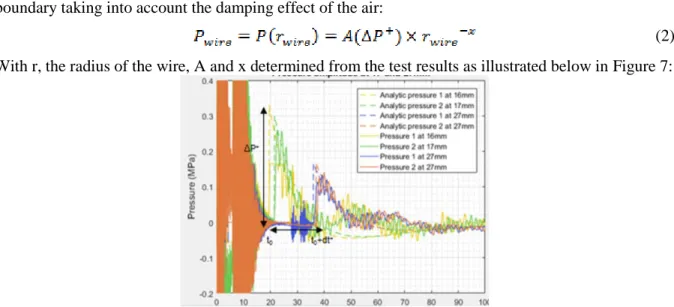
From pressure measurements at different distances and with different amplitudes and lightning waveforms, an experimental law was created to obtain the maximum pressure ΔP+
at the wire boundary taking into account the damping effect of the air:
(2) With r, the radius of the wire, A and x determined from the test results as illustrated below in Figure 7:
Figure 7 Pressure measurements at 17 and 27 mm for one configuration
2.1.1 Lab test results
As mentioned in the previous chapter, several pressure measurements at different distances from the exploding wire have been performed on different configurations. Those configurations are based on the variation of the waveform shape (WF1 vs WF5A), of the amplitude (5 vs 10kA) and of the wire radius (ECF195 vs ECF73). In Figure 8, the pressures plotted have been normalized to the pressure measured at 40mm. This is why only one spot is visible at 40mm and is equal to 1. The purpose of this normalization is to assess the pressure law independently from the pressure amplitude at the origin.
Figure 8 Pressure law from test measurement
Based on this law, it is possible to extrapolate the maximum pressure generated by different configurations with an extract presented in Table 1:
Pressure at the wire (MPa)
WF1 10kA WF1 5kA WF5A 10kA WF5A 5kA
ECF195 290 160 218 127
ECF73 157 138 N/A 61
Table 1 Wire overpressure with different lightning current
2.2 Wire explosion shock wave model
The pressure generated by the sudden vaporization of the wire is considered as a shock wave which is defined by the following equation for the positive overpressure:
(3)
With:
• Time of arrival (t0)
• Maximum positive overpressure (ΔP+
) • Positive phase duration (dt+
) • Positive impulsion (I+
)
This specific pressure signature is illustrated in Figure 9 below:
Figure 9 Shock wave pressure waveform
For ECF195, based on the test results of current density and pressure, an empirical model has been built. The overpressure (MPa) generated by a wire explosion has been expressed as a function of the maximum current Ip (kA) injected in a section of equivalent wire with WF1:
(4) In this configuration, a=80.3, b=0.64 and c=-62.88.
3 SHOCK WAVE PROFILE LOAD
As already developed previously [17-20], mechanical models are considered in order to simulate lightning strike as an overpressure on the composite panel. Most of them are considering a fixed surface of application or based on the theory of a free arc.
3.1 Load theory
In our study, the pressure model is dependent on time and space for the distribution and amplitude. For the distribution, an empirical model has been built based on the measurement of the vaporization profile for a given lightning strike protection with paint confinement effect. For the amplitude of the pressure, another empirical model is considered based on the measurement of shock wave generated by an exploding copper wire. The pressure has been related to the current injected to each wire and the assessment of this current distribution is made thanks to the record on the number of intersections between the vaporization profile and the lightning strike protection web. The combination of those models allow us to apply an evolving pressure on the surface of a composite panel in order to simulate the overpressure generated by a lightning strike in interaction with a metallic protection covered by paint: P(x,y,t). This pressure load is a defined in equation 4 for the peak amplitude ΔP+ and equation 3 for the waveform with a dependent dt+ defined as ( ΔP+max/ ΔP+)0,8dt+0 and dt+0 =3µs.
3.2 Mechanical Model - VDLOAD
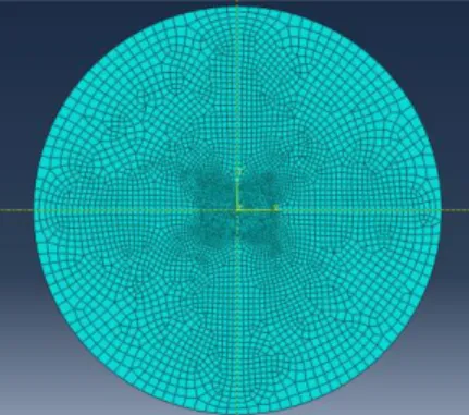
Lightning damage to composite structure is a complex multiphysical phenomenon but there is clearly an interest to build a simplified approach with an equivalent mechanical model. In our study, we have considered Abaqus Explicit ® in which user damage law thanks to VUMAT subroutine from Hashin [21]. In addition, a VDLOAD subroutine has been developed in order to apply the pressure load on the top surface as defined previously: P(x,y,t). In order to validate this new subroutine, a first model without damage assessment has been built. Expected result considered for this validation step is the rear face displacement over time. In Abaqus Explicit, a single layer of shell finite elements (S4R) with CFRP elastic material properties (see Table 2), and a user defined load on the top surface have been implemented.
Density 1.6E-3 g.mm-3
Elastic modulus E11 165 GPa
Elastic modulus E22 7.64 GPa
Elastic modulus G12 5.61 GPa
Elastic modulus G13 5.61 GPa
Elastic modulus G23 2.75 GPa
Poisson’s ratio ν12 0.35
Table 2 CFRP elastic properties
This model simulates a CFRP panel bonded on a circular frame of Ø370mm which has been in a lightning laboratory lab with different lightning strike protection. The frame is considered by adding clamped boundary conditions at the border of the disk.
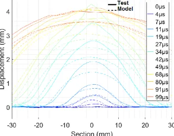
The purpose of this first step is to assess the consequence of this first loading and validate it create a similar deflection. Even if not identical, this is important to get the same order of magnitude in order to generated a similar loading of the structure and then assess the damage in the CFRP. For a CFRP panel covered by thick paint, we know that there will be an interaction with the lightning arc which will create internal damages and explosions during the application of pressure on the surface. The results are presented, in Figure 11, where we can see that the test deflection presents a more “protruding” profile than with the model.
Figure 11 Displacement of CFRP panel - Comparison between test and model
Even if important in the damage mechanism process, the internal explosion and fiber breakages have a negligible contribution in the global deflection profile. This is an interesting information since it means that we can decorrelate the overpressure profile generated on the surface by the explosion of the metallic lightning strike protection and the internal fiber breakages and explosions.
3.3 Mechanical damage Model – VDLOAD & VUMAT
We can now consider a 3D model with a damage law provided through a VUMAT based on Hashin theory [21]. The loading from the VDLOAD will be the same one than the law consider with the shell configuration. In addition to the material law, cohesive behavior and damage criteria have been added to the contact between plies to simulate delamination. This model presented a similar displacement profile, which demonstrates that the pressure load was correctly applied, but no damage has been generated in the CFRP panel. However, after a lightning strike on this CFRP panel (13 plies), protected with ECF195 and 400µm of paint, damage is expected as illustrated in Figure 12 the below:
Figure 12 NDT result - CFRP damage
It therefore demonstrates the importance of the combination of the top pressure load applied on the panel and the internal damage on the carbon fiber due to the current flow.
4 INTERNAL CURRENT DISTRIBUTION
During a lightning strike, a composite structure is subjected to mechanical constrains from the surface explosion, as mentioned in the previous chapter, but also to electro-thermal constrains.
Indeed, because of the presence of the paint, the lightning arc can’t move freely and part of his current will be injected into the first plies of CFRP, left unprotected by the vaporization of the protection. The more the paint thickness increase, the more the current is injected into CFRP. In the Figure 13 below is presented the result of lightning strike test (100kA) on GFRP panel covered with one ply of CFRP (-45°), ECF195 and several paint thicknesses: 200, 400, 600 and 800µm. Dry fiber is the evidence of current injection into the CFRP ply which heated quickly due to Joule effect. With 200µm of paint, the CFRP ply is almost not damage and, on the opposite, with 800µm of paint, the fibers (-45°) are dry in the center and started to disbond from the panel.
Figure 13 CFRP Current injection with paint thickness increase
Still, the profile of vaporized ECF is not significantly changed which means this is a very amount of the total current is sufficient to explode the carbon fibers and the resin around.
If we look at a cross section of a full CFRP panel, protected with ECF195 and painted with 400µm of paint, this is the first top ply (among 13 plies) that is mainly damaged by current injection.
4.1 Lab test
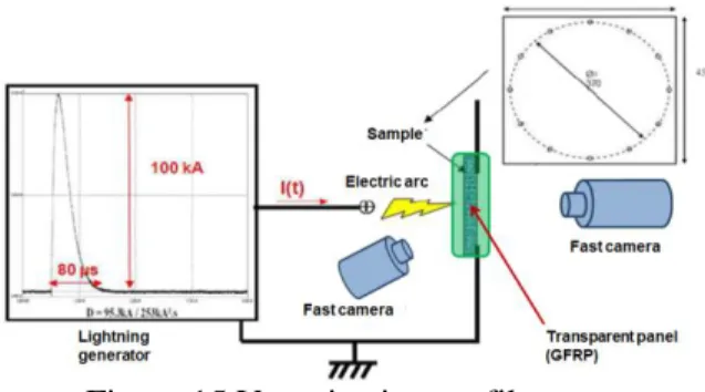
In order to assess the damage to the composite fibers due to current injection, a specific test set up has been built. The panel configuration shown in Figure 13 is used to measure the damage in one ply f CFRP. Due to the high luminosity of the electrical arc, it is almost impossible to record the vaporization profile of the LSP. The method developed uses the transparency of the fiberglass panel and a high speed camera (1Mfps) placed on the rear face of the panel to record this vaporization profile as shown in Figure 15.
Figure 15 Vaporization profile set up
In Figure 16, we can see the impact of the paint thickness on the current injection in the CFRP ply. The time in µs represented the last moment of light recorded and the distance in mm, the highest one measured from the center of injection. The paint thickness increases the time of current injection in the composite but also the distance. The light should be still interpreted carefully as it is certainly a combination of light coming from the ECF vaporization on the top which is visible through the damage CFRP ply (not transparent) and the light created by the extreme heating of the carbon fibers.
Figure 16 Vaporization profile with CFRP
4.2 Empirical damage model
For the comparison with test results, we will consider a CFRP panel configuration with ECF195, covered by 400µm of paint. In this configuration, only the first ply is damaged. The injection, and thus associated damage to the first carbon ply, is related to the vaporization of ECF195 on the top. Thus, we could combine the profile shown in Figure 5 to the first carbon ply in the 45° direction. In a first step, we have decided to consider a fix damage that will be introduced at the start of computation without any change. The size of the damage is presented in the Figure 17 below:
9 CONCLUSIONS
The objective of the work presented in this paper was to decompose loading due to the lightning strike on composite structure and analyses the associated damage phenomenon. Indeed, this is a really complex and multiphysical mechanism that generates the damage into a composite structure. The lightning arc itself is already complex to study, but it is even more complicated considering its interaction with the substrate which is not a simple homogeneous material. Indeed, this is a composite carbon panel covered by a thin metallic protection which vaporizes during the event and is, on top, covered by paint. This paint has 2 effects: to limit the arc root expansion and to confine the gas generated by the vaporization of the lightning strike protection.
For the pressure load to apply on the composite structure, a first part of the work has been focused on the electric explosion produced by the vaporization of the lightning strike protection by considering it as a web of copper wires. The explosion effect has been studied individually on wire in order to build phenomenological laws which relate the shock wave profile to the current density.
Finally, a mechanical model in abaqus with a VDLOAD subroutine has been built in order to study the effect of the vaporization profile on the panel deflection which can be compared to lightning test results. This loading has been then combined with a VUMAT and interaction law between plies in order to assess the damage only due to the mechanical load.
It has been shown that this loading only can’t generate the damage and it is thus necessary to couple it with internal damage due to the electrothermal effect of the current flow into the CFRP. For this purpose, specific tests have been performed in order to measure this distribution and a damage model has been proposed. This introduction of internal damage with the current VUMAT & VDLOAD is part of our future developments.
ACKNOWLEDGEMENTS
This work is part of a PhD in collaboration between 2 academic laboratories: ICA (Institut Clément Ader) and GREMI (Groupe de Recherches sur l'Energétique des Milieux Ionisés), and an industrial partner: Airbus. We are gratefully thankful for their support in the different test developments and model creations.
REFERENCES
[1] L. Chemartin, P. Lalande, B. Peyrou, A. Chazottes, P.Q. Elias, “Direct Effects of Aircraft Structure: Analysis of the Thermal, Electrical and Mechanical Constraints”, Journal of
Aerospace Lab, Issue 5 (2012)
[2] Chippendale, Richard. “Modelling of the Thermal Chemical Damage Caused to Carbon Fibre Composites.” PhD, University of Southampton, 2013
[3] Dong, Qi, Yunli Guo, Xiaochen Sun, and Yuxi Jia. “Coupled Electrical-Thermal-Pyrolytic Analysis of Carbon Fiber/Epoxy Composites Subjected to Lightning Strike.” Polymer 56 (January 2015): 385–94
[4] Ogasawara, Toshio, Yoshiyasu Hirano, and Akinori Yoshimura. “Coupled Thermal–electrical Analysis for Carbon Fiber/Epoxy Composites Exposed to Simulated Lightning Current.”
Composites Part A: Applied Science and Manufacturing 41, no. 8 (August 2010): 973–81
[5] Wang, Y., and O. I. Zhupanska. “Evaluation of the Thermal Damage in Glass Fiber Polymer-Matrix Composites in Wind Turbine Blades Subjected to Lightning Strike.” In Proceedings of
American Society for Composites, 29th Annual Technical Conference, San Diego, CA, 2014
[6] Wang, F.S., Y.Y. Ji, X.S. Yu, H. Chen, and Z.F. Yue. “Ablation Damage Assessment of Aircraft Carbon Fiber/Epoxy Composite and Its Protection Structures Suffered from Lightning Strike.” Composite Structures 145 (June 2016): 226–41
[7] A. Bigand, Y. Duval, “Quantification of the mechanical impact of lightning strike protection explosion confined by thick paint”, Int. Conf. on Lightning and Static Electricity (Nagoya) 2017.
[9] Rafael Sousa Martins, “Experimental and theoretical studies of lightning arcs and their interaction with aeronautical materials”, Ph. D. thesis, Université Paris-Saclay (2016).
[10] A. Bigand et al., “Estimation of the load produced by the electro-thermal behaviour of lightning strike protection layers on a composite panel”, ECCM18 - 18th European Conference on
Composite Materials (Athens) June 2018.
[11] Rodríguez et al. « Dynamics of a Shock Wave with Time Dependent Energy Release Generated by an Exploding Wire in Air ». Physics of Plasmas 25, no 11 (nov 2018)
[12] Li et al. « Study of the Shock Waves Characteristics Generated by Underwater Electrical Wire Explosion ». Journal of Applied Physics 118, no 2 (14 july 2015)
[13] Chung et al. « Numerical Model for Electrical Explosion of Copper Wires in Water ». Journal
of Applied Physics 120, no 20 (28 nov 2016)
[14] Ivanenkov et al« Current Shunting and Formation of Stationary Shock Waves during Electric Explosions of Metal Wires in Air ». Plasma Physics Reports 36, no 1 (1 Jan 2010)
[15] Han et al « Relationship between Energy Deposition and Shock Wave Phenomenon in an Underwater Electrical Wire Explosion ». Physics of Plasmas 24, no 9 (sept 2017)
[16] Grinenko et al « Efficiency of the Shock Wave Generation Caused by Underwater Electrical Wire Explosion ». Journal of Applied Physics 100, no 11 (2006)
[17] F. Soulas, C. Espinosa, F. Lachaud, S. Guinard, B. Lepetit, I. Revel, Y. Duval, “A method to replace lightning strike tests by ball impacts in the design process of lightweight composite aircraft panels”, International Journal of Impact Engineering 111 (2018) 165-176.
[18] B. Lepetit, F. Soulas, S. Guinard, I. Revel, G. Peres, “Analysis of composite panel damages due to a lightning strike: mechanical effects”, Int. Conf. on Lightning and Static Electricity (Seattle) 2013.
[19] Liu, Z. Q., Z. F. Yue, F. S. Wang, and Y. Y. Ji. “Combining Analysis of Coupled Electrical-Thermal and BLOW-OFF Impulse Effects on Composite Laminate Induced by Lightning Strike.” Applied Composite Materials 22, no. 2 (April 2015): 189–207
[20] C. Karch, R. Honke, J. Steinwandel, K.W. Dittrich, “Contributions of lightning current pulses to mechanical damage of CFRP structures”, Int. Conf. on Lightning and Static Electricity
(Toulouse) 2015.
[21]
Hashin, Z., “Failure Criteria for Unidirectional Fiber Composites,” Journal of Applied
Mechanics, vol. 47, pp. 329–334, 1980
[22] F. Lago et al., “Measurement by a digital image correlation technique of the deflection of panels submitted to lightning pulse currents”, Int. Conf. on Lightning and Static Electricity (Oxford) 2011.