HAL Id: tel-00659821
https://tel.archives-ouvertes.fr/tel-00659821
Submitted on 13 Jan 2012HAL is a multi-disciplinary open access archive for the deposit and dissemination of sci-entific research documents, whether they are pub-lished or not. The documents may come from teaching and research institutions in France or abroad, or from public or private research centers.
L’archive ouverte pluridisciplinaire HAL, est destinée au dépôt et à la diffusion de documents scientifiques de niveau recherche, publiés ou non, émanant des établissements d’enseignement et de recherche français ou étrangers, des laboratoires publics ou privés.
Sarah Suck
To cite this version:
Sarah Suck. Digital Heterodyne Holography for Plasmonic Nanostructures. Optics [physics.optics]. Université Pierre et Marie Curie - Paris VI, 2011. English. �tel-00659821�
THÈSE DE DOCTORAT
DE L’UNIVERSITÉ PIERRE ET MARIE CURIE
Spécialité
Physique
(ED 397 - Physique et Chimie des Matériaux)
Préparée à l’Institut Langevin - Ondes et Images
Présentée par
Sarah Yasmine Suck
Pour obtenir le grade de
DOCTEUR de l’UNIVERSITÉ PIERRE ET MARIE CURIE
Sujet de la thèse :
Digital Heterodyne Holography
for Plasmonic Nanostructures
Soutenue le 02 novembre 2011
devant le jury composé de :
M. BOUHELIER Alexandre Rapporteur M. COLLIN Stéphane Examinateur Mme DEL FATTI Natalia Rapporteur M. DE WILDE Yannick Membre invité Mme MAÎTRE Agnès Président
M. TESSIER Gilles Directeur de thèse M. VOGELGESANG Ralf Examinateur
Université Pierre & Marie Curie - Paris VI Tél Secrétariat : 01 42 34 68 35 Bureau d’accueil Fax : 01 42 34 68 40 Inscription des doctorants et base de données Tél pour les étudiants de A à EL : 01 42 34 69 54 Esc G, 2eétage Tél pour les étudiants de EM à MON : 01 42 34 68 41
15 rue de l’École de Médecine Tél pour les étudiants de MOO à Z : 01 42 34 68 51 75270 PARIS Cedex 06 E-mail : [email protected]
Remerciements
D
e faire une thèse n’est pas un travail solitaire, mais un travail en équipe, dans un groupe avec des échanges réguliers, dans un laboratoire avec des contributions de plusieurs personnes. Ici je voudrais m’en servir de quelques pages de mon manuscrit pour remercier à toutes les personnes qui ont contribué à un très bon déroulement de ma thèse. Tout d’abord je tiens à remercier Natalia Del Fatti et Alexandre Bouhelier pour avoir accepté de rapporter sur mon travail. Je remercie aussi Agnès Maître, Stéphane Collin et Ralf Vogelgesang pour avoir accepté d’être membres du jury de thèse comme examina-teurs. Grâce à un jury très intéressé et curieux j’ai pu profiter d’un échange très fructueux et animé pendant la discussion de ma soutenance.Un remerciement particulier va à la Fondation Pierre-Gilles de Gennes qui m’a permis de faire ma thèse en premier lieu grâce à son financement pendant ces 3 ans. Je remercie aussi son directeur, M. Gilles Rubinstenn, qui a poursuivi ma thèse un peu de loin mais toujours avec beaucoup d’intérêt.
Les deux personnes à qui je dois le plus sont mes deux directeurs de thèse: Gilles et Yannick. En premier lieu ils m’ont accepté comme doctorante bien que j’étais sans aucun background optique. Néanmoins ils m’ont aidé beaucoup à obtenir le financement pour faire une thèse chez eux et m’ont soutenu dès le début de ma thèse.
Gilles a su partager avec moi sa solide expertise dans la domaine d’optique expéri-mentale et théorique. Gilles était toujours disponible quand j’avais des questions ou des problèmes de manips. Son encadrement et son soutient ont été indispensables à la réus-site de mon travail. Gilles était toujours ouvert à des nouveaux idées ou des projets. Un exemple est le projet de simulation: quand je voulais commencer des simulations des propriétés optiques - malgré notre ignorance mutuelle - Gilles s’est montré toute de suite très intéressé et a acheté sans un cillement le matériel nécessaire (le logiciel coûteux et un ordinateur puissant). Grâce à sa patience, son calme et sa sérénité il était très agréable de travailler ensemble avec Gilles ce que j’ai beaucoup apprécié durant ma thèse!
Le jour de ma soutenance Yannick s’est défini comme “assistant” (et pas comme en-cadrant) dont je ne suis pas d’accord. La raison pour sa définition venait probablement du fait que Yannick et moi n’avions jamais eu d’occasion de vraiment travailler ensemble bien que il a été prévu. Malheureusement le temps limité de la thèse ne le permettait plus.
Mais au contraire j’ai vu Yannick toujours comme mon (deuxième) directeur de thèse. Il était toujours intéressé à mes avancements pendant ma thèse. J’ai partagé avec Yannick mes approches, mes problèmes, mes avancés et mes résultats. Et quand je rencontrais des problèmes, Yannick a souvent su donner des conseils très appréciés pour les résoudre et surmonter. Yannick est toujours de bonne humeur et souriant, non seulement très tôt le matin quand il fait son tour de dire bonjour au monde, mais aussi très tard le soir, et toujours dispo pour discuter de ci et ça, même dans des moments de stress.
Nous n’avons pas eu une vie de groupe ”classique“; dans le sens que nous avons travaillé tous dans le même thématique de la plasmonique mais sur des sujets très différents. Au début de ma thèse nous avons eu entre des membres de groupe peu d’échanges sur nos différents projets. Vers le dernier tiers de ma thèse Yannick et Gilles ont initié des réunions de groupe hebdomadaires que j’ai apprécié beaucoup! Pendant nos discussions (plus au moins animés dépendant de la réactivité des personnes à l’heure matinale) autour du café et souvent trop de croissants et de viennoiseries, j’ai appris beaucoup, à la fois des travaux au sein de notre groupe et des travaux des autres laboratoires partout dans le monde. Merci à Nok, Arthur et Léo pour leurs présences et leurs contributions!
Je dois remercier beaucoup “l’équipe” de LPN: Nathalie Bardou qui à participé énor-mément à la fabrication difficile des échantillons précieuse, Christophe Dupuis qui a mené avec son expertise l’observation et la caractérisation des nanostructures et avec qui j’ai passé des heures rigolos devant le MEB. Bien-sûr je n’oublie pas à remercier Stéphane Collin. Sans son collaboration et son expertise ma thèse n’aurait pas pu être réalisé! C’était une collaboration très agréable et très fructueuse.
Je voudrais remercier Sébastien qui m’a fait découvrir les “dark modes”. Son expertise dans la plasmonique et sa connaissance immense de tout ont apporté beaucoup des idées intéressants, des aperçus fascinants sur mon sujet et ont attribué à l’analyse des résultats. Finalement, grâce à Seb et à ses commentaires toujours constructives nous avons publié ensemble un très beaux article!
Je tiens à remercier Rémi Carminati. Son expertise dans la théorie est incontestée, sa connaissance de l’optique est infiniment vaste et son éloquence impressionnante. Pendant ma thèse il a évoqué son intérêt à la technique de l’holographie hétérodyne (Rémi a aussi fourni une partie de l’analyse pour ma thèse) et m’a assurée de l’intérêt et de l’avantage de cette technique dans le monde de la plasmonique.
Je voudrais remercier Srdjan Acimovic qui a fait sa thèse à l’ICFO. Je l’ai connu sur internet à travers des forums de physique qui discutaient des simulations dans la plas-monique en utilisant Comsol. Srdjan m’a donné beaucoup des conseils qui m’ont fait avancé quand j’avais des problèmes avec Comsol.
disponi-iii bilité pendant les TP que j’ai eu d’occasion d’avoir encadré avec eux.
Many thanks au meilleur bureau du monde: Étienne, Virginie, Valentina, Rémi et Hugues. On a rigolé beaucoup pendant ces derniers 3 ans. L’atmosphère dans notre bureau a contribué beaucoup à la joie de venir au travail et a adouci chaque jour du travail, en outre des bonbons qui ne manquaient jamais!
Bien-sûr, je n’oublie pas dans mes remerciements mes voisines du bureau à côté: Salma, Karla, Ioana, Nok et Emilie! Les ”filles“ avaient des bons conseils pour des problèmes et tenaient toujours un sourire toutes prêtes ce qui a soulevé mon esprit immédiatement quand quelque chose allait mal.
La Montagne a aussi contribué à avoir passé beaucoup des bons moments avec des collègues et des amis du labo autour d’un verre de T-Punch ou d’une pinte de bière, absorbés dans des discussions scientifiques ou plus souvent non-scientifiques.
Un grand merci va aussi à Daniel qui nous (nous = venant de l’ESPCI) a permis de participer à son cours de ”renforcement musculaire“ à l’ENS. Bien-sûr sans Max je n’aurais jamais découvert ce cours. Merci, Max, aussi pour ta bonne humeur imperturbable. Merci aussi aux autres co-sportifs Étienne et Anne! C’était toujours un plaisir de m’activer d’une manière sportive. Le sport du jeudi midi me manquera beaucoup.
Voici une liste (pas exhaustive) de tous ceux qui se sont pas encore trouvé dans la liste de remerciement, mais à qui je voudrais remercier. Sans eux cette expérience aurait été différemment:
Sonia (!), Elika, Sandrine, Arik, Dominika, Jochen, Benedikt, Matthias, Stéphanie, Christelle, Delphine, Corinne, Matthias et TV5 dans ma salle de manips, Patricia, Em-manuel, Jean-Marie, Claude, SSOP1, Cargèse, Porquerolles, Mario et ses cafards, Taek-wondo, Jonas, Heldmuth, Alexandre, Michaël, Mickaël, Michael (ceci n’est pas une faute de frappe), Cédric, Natalia, Caroline, Charles, Sylvie, Lara, Charles et son rhum délicieux, Alexandre, Emanuele, Nazim, Romain, Farin Urlaub, Tom, Matthias, Micha, Thomas und Judith, Daniel, PC Café, Die Ärzte, Beatsteaks, des pique-niques aux champs de mars, Montsouris, Lucie, Fadi, Georges, Steve, Anis, 2× Julien, Pierre, Cyril, Maxime, Mattia et Delphine, Vélib, Dexter, Game of Thrones, Big Bang Theory, Quartier Latin, financiers aux thé vert, Golosino, Sorin, Yasmina, Michaela, Roberta, Gym Combat, Marcoussis, grèves, Vendé, Saint Gildas, Honfleur, Mme Denis, Bordeaux, Thaïlande, San Francisco, Dresden, DPG, CLEO, Matlab, Google, Danielle Fournier, M. Bok, la salle stagiaires, LaTeX, la Sardaigne, le Champagne à et de Troyes, l’Internationale, Julie, Take it Easy, les fêtes, Picard, Hoa, la bière à Leuven, linie 21, Radium, Marie Curie, Paula, Sylvain et Alice, Elena, Christoph und Bertille, Giorgio, Kevin, Michele et Marie, Alessandro, Enrico, footings, les catacombes (I’m still waiting, Sylvain), parc floral, Roberto, Sergio e Maria, Time Warp, Thriller, cupcakes, Lavazza, spiegel.de, et ... Paris.
Entscheidungen unterstützt haben (und sogar bis nach Paris mit dem Auto gefahren sind, um mir bei meiner Verteidigung beizustehen und Bier und Plätzchen aus Deutschland mitzubringen...). Ohne sie und deren Sichtweise auf die Dinge von aussen (beim wahrsten Sinne des Wortes) wäre alles viel schwieriger gewesen. Danke!
Finalmente, un grande ringrazio va a Romano: mio amore, mio amico, mio compagno senza di liu gli ultimi tre anni sarebberonno stati molto piu difficile. Romano mi ha sempre incoraggiato et risollevato quando avevo i dubbi delle mie decisione e non ha mai smesso di sostenermi. Grazie!
Abstract
In this thesis we study the scattering characteristics of plasmonic nanostructures by im-proving and adapting digital heterodyne holography, which is a powerful tool delivering a three-dimensional cartography of scattered light, and which has the advantage of allowing fast full-field imaging.
Spectroscopic measurements were carried out to record the scattering spectra of single nanoobjects and complement holographic measurements. In order to get a deeper insight into the measured far-field scattering characteristics, we developed a numerical model based on the finite element method. This model allowed us to simulate the scattered fields of nanostructures both in the near- and far-field either in a reflection or transmission configuration for the illumination. The model yielded a good agreement with experimental results.
We studied numerous gold nanostructures prepared by electron beam lithography on glass substrates, ranging from simple, elementary nanoobjects to novel nanostructures. While the former allowed us to validate the technique, more sophisticated structures allowed us to observe that their scattering pattern is extremely sensitive to external and internal factors, such as the polarization and the wavelength of the incident light or the structure’s geometry and its resonance wavelength. We recognize so called “hot spots” in the far-field, which are zones on the chain that scatter light more intensely than others. In addition, we show that the technique of photothermal heterodyne holography is a novel method to study the temperature increase and heat distribution in heated plasmonic nanostructures due to its ability to directly probe a temperature increase.
Keywords
digital holography; nanoantennas; radiation patterns; photothermics; numerical simula-tion; heterodyne detection
Résumé
Dans cette thèse, nous étudions les caractéristiques de diffusion de nanostructures plas-moniques tout en adaptant et améliorant l’holographie hétérodyne numérique, qui est une technique d’imagerie plein champ pour mesurer en trois dimensions le diagramme de rayonnement. En outre, nous avons effectué de nombreuses mesures spectroscopiques pour enregistrer les spectres de diffusion de nanoobjets uniques. Afin d’obtenir une com-préhension plus profonde des caractéristiques du champ diffusé que nous mesurons, nous avons développé un modèle numérique basé sur la méthode des éléments finis. Ce modèle nous a permis de simuler le champ proche et le champ lointain d’une nanostructure avec une onde incidente en réflexion ou en transmission. Nous obtenons un excellent accord entre nos résultats expérimentaux et calculés.
Dans cette thèse, nous avons étudié de nombreux nanostructures d’or fabriquées sur du verre par lithographie électronique. Des structures simples nous ont permis de valider la technique. Des objets plus sophistiques nous ont ensuite permis de constater que leur di-agramme de diffusion est extrêmement sensible aux facteurs externes et internes, tels que la polarisation et la longueur d’onde de la lumière incidente ou la géométrie de la struc-ture et sa longueur d’onde de résonance. En outre, nous montrons que la technique de l’holographie hétérodyne photothermique mesure directement l’augmentation de la tem-pérature, et ainsi, se présente comme une nouvelle méthode pour étudier la distribution de la chaleur dans des nanostructures plasmoniques.
Mots-clefs
holographie numérique; nanoantennes; diagramme de diffusion; photothermique; simula-tion numérique; détecsimula-tion hétérodyne
Titre de la thèse
Contents
Introduction xiii
1 Plasmonics and Optical Antennas 1
1.1 A Short Introduction to Plasmonics . . . 3
1.1.1 Surface Plasmon Polaritons . . . 4
1.1.2 Localized Surface Plasmons . . . 5
1.1.3 Single Particle Plasmon Resonances - The Quasi-Static Approxima-tion . . . 6
1.1.4 Theoretical Considerations beyond the Quasi-Static Limit: Retar-dation Effects . . . 8
1.2 Optical Antennas . . . 9
1.2.1 Properties of Optical Antennas . . . 9
1.2.2 Nanoantenna Geometries . . . 10
1.2.3 Applications of Optical Antennas - State of the Art . . . 12
1.3 Conclusion . . . 15
2 Digital Heterodyne Holography 17 2.1 Historical Overview . . . 19
2.2 Principles of Holography . . . 20
2.2.1 Off-Axis Holography . . . 23
2.3 Digital Holography . . . 24
2.3.1 Numerical Holographic Reconstruction . . . 25
2.3.2 Phase Shifting Holography . . . 28
2.3.3 Digital Heterodyne Off-Axis Holography . . . 30
2.3.4 Experimental Setup of DHH . . . 32
2.4 Photothermal Heterodyne Holography . . . 35
2.4.1 Experimental Setup of Photothermal DHH . . . 36
2.5 Frequency Domain Detection by Heterodyne Holography . . . 37
2.5.1 Application 1: Frequency-Resolved Temperature Imaging of Inte-grated Circuits . . . 38
2.5.2 Application 2: Frequency Detection in the Brownian Regime of
Gold Nanorods . . . 45
2.5.3 Conclusion on Frequency Detection . . . 53
2.6 Conclusion on Digital Heterodyne Holography . . . 53
3 The Nanostructures under Study 55 3.1 Design of the Nanostructures . . . 57
3.1.1 Nanostructure Fabrication . . . 60
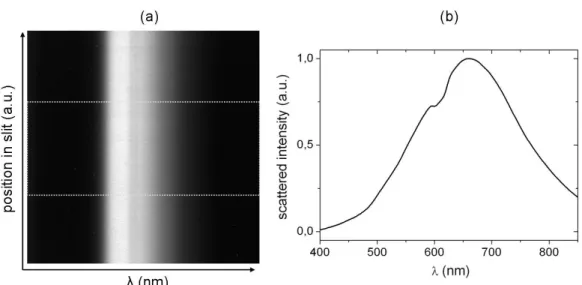
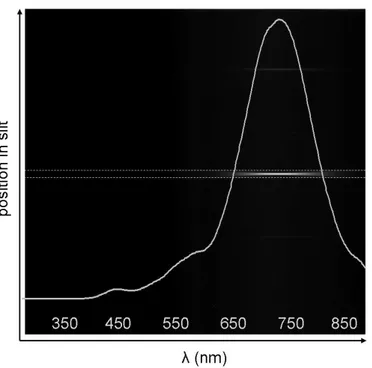
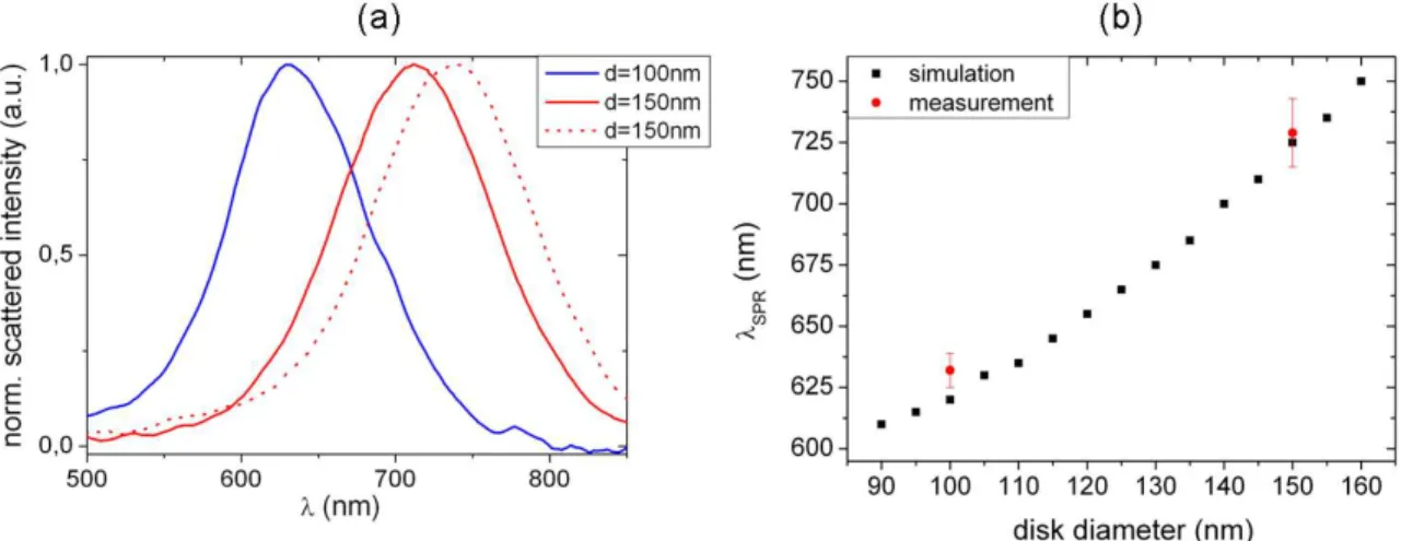
3.2 Spectroscopy of Single Nanoobjects . . . 62
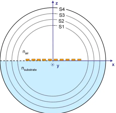
3.3 FEM Simulation of Plasmonic Nanoobjects . . . 65
3.3.1 Scattering in the Far-Field . . . 67
3.3.2 Scattering in the Near-Field . . . 68
3.3.3 Tests for Validation . . . 69
3.4 Conclusion . . . 70
4 Validation of Experimental Techniques on Elementary Nanoobjects 71 4.1 Single Nanodisks . . . 74
4.1.1 Light Scattering by a Single Disk . . . 75
4.1.2 Near-Field of Single Disks . . . 76
4.1.3 Holography of Single Disks . . . 78
4.1.4 Conclusion on the Scattering Behaviour of Single Disks . . . 80
4.2 Coupling of Two Nanodisks . . . 81
4.2.1 Introduction to the Study of Two Coupled Disks . . . 82
4.2.2 Plasmon Hybridization Model . . . 84
4.2.3 Scattering Spectra of Two Coupled Disks . . . 85
4.2.4 Study of Different Modes Excited in Two Coupled Disks . . . 89
4.2.5 Conclusion on Two Coupled Nanodisks . . . 95
4.3 Two Coupled Nanorods . . . 96
4.3.1 Light Scattering of Coupled Rods . . . 96
4.3.2 Near-Field of Single and Coupled Rods . . . 98
4.3.3 3D Far-Field Images of Light Scattered by Coupled Rods . . . 99
4.3.4 Conclusion on Coupled Rods . . . 101
4.4 Conclusion . . . 101
5 Extensive Study of Plasmonic Nanostructures 103 5.1 Probing the Coupling of Nanodisk Chains by Spectroscopy . . . 107
5.1.1 Longitudinal and Transverse Modes in Nanodisk Chains . . . 107
5.1.2 Far-Field Scattering Revealing Near-Field Coupling in Nanodisk Chains . . . 110
Table of Contents xi
5.2.1 The Influence of the Chain Length on the Far-Field Maps . . . 115
5.2.2 TE Wave and TM Wave Excitation . . . 117
5.2.3 Imaging of Longitudinal and Transverse Modes in a Chain . . . 122
5.2.4 Influence of the Exciting Wavelength . . . 126
5.2.5 Probing the Coupling of Nanodisk Chains by Holography . . . 131
5.2.6 Imaging of Directional Scattering . . . 133
5.2.7 Conclusion on the Far- and Near-Field Maps of Nanodisk Chains . 136 5.3 Probing the Plasmonic Coupling of Disks by Heating . . . 136
5.3.1 Comparison of Holographic and Photothermal Images . . . 137
5.3.2 Photothermal Imaging of Nanostructures - An Analytical Analysis of the Photothermal Signal . . . 139
5.3.3 Photothermal Signal and Absorption Cross Section . . . 142
5.3.4 Photothermal Holography Reveals Coupling of Nanodisk Chains . . 144
5.3.5 Conclusion on Photothermal Imaging of Nanodisk Chains . . . 149
5.4 Coupled Triangles . . . 150
5.5 Conclusion on the Application of Holography to Plasmonics . . . 156
Conclusions and Prospects 159 A FEM Simulation Parameters - Fresnel Coefficients 163 A.1 Excitation Field in Reflection . . . 163
A.2 Excitation Field in Transmission . . . 164
B Square-Wave Function in Matlab 171
Introduction
P
lasmonics is an upcoming discipline that is primarily concerned with the manipulationof light at the nanoscale. Plasmonics explores the interaction processes between light and metal nanofilms or metal nanostructures. One of the most fascinating features of plasmonic structures is their ability to squeeze light into volumes less than one hundredth of a wavelength in size which is quite spectacular if one thinks about it.Interesting effects such as this make plasmonics a very attractive research field which is rapidly developing in physics, biophotonics, chemistry and medicine, numerous potential and promising applications. These range from enhanced sensing and spectroscopy for chemical identification and detection of biomolecules or biological agents, drug design, high-resolution microscopy, to signal propagation with metal-based waveguides and solar cells.
The characteristic near- and far-field of a plasmonic nanostructure can be regarded as its fingerprint. The far-field of a plasmonic nanostructure delivers information about its plasmon resonance, whereas the near-field gives access to its capability to enhance and confine fields. The angular emission or scattering of nanostructures is particularly interesting when dealing with nanoantennas, since one of their most interesting functions is their ability of controlling the direction of emission. Techniques that allow to gain insight into the angular scattering information are important for the study of nanoantennas. Therefore, it is fundamental to obtain the full knowledge of the three-dimensional (3D) electromagnetic field around a nanoobject interacting with a light source, in order to exploit and tune the plasmon properties of nanostructures.
Today, however, few experimental tools exist to obtain a complete three-dimensional knowledge of the electromagnetic field. In order to record the electromagnetic field in three dimensions either scanning techniques have to be used or techniques that allow the measurement of the field’s amplitude and phase. Scanning near-field optical microscopy achieves exceptional resolutions and has also proven its ability to detect both amplitude and phase of electromagnetic fields in plasmonic structures (Hillenbrand and Keilmann 2000; Vogelgesang et al. 2008; Esteban et al. 2008). However, this technique remains of heavy use, is time consuming and restricted to the near-field.
A technique that gives access to the angular information of the electromagnetic field is back focal plane imaging. The back focal plane of a bright-field reflection microscope or of a confocal microscope contains information about the sample, as positions in the back
focal plane map to diffraction angles from the sample. This kind of imaging has been applied recently to nanoantennas in order to map their emission patterns (Curto et al. 2010).
A couple of years ago, our laboratory developed the technique of (off-axis) digital het-erodyne holography and showed that this technique is very well adapted to the detection of weakly scattering objects, like nanoobjects, due to its excellent sensitivity (Gross and Atlan 2007). It has been successfully applied to image and localize metal nanoparticles of 50 nm diameter in three-dimensions, either for fixed particles spin coated on a glass substrate or in free motion within a water suspension (Atlan et al. 2008; Absil et al. 2010). More recently, it has been shown that gold nanobeads, functionalized and fixed on the membrane of live cells, can be detected in order to obtain a three-dimensional image of the cell surface (Warnasooriya et al. 2010; Joud et al. 2011).
One of the main advantages of holography, a technique that relies on interferometry, is its ability to measure the amplitude and phase. Therefore, one hologram, which can be measured in less than 1 second, contains the whole 3D information of the recorded scattered light. Furthermore, holography allows also the access to the angular scattering pattern of a nanostructure since the angular spectrum of the hologram can be obtained by computing the scattered field in the Fourier space. Hence, digital heterodyne holography proves to be a powerful tool to deliver a three-dimensional cartography of the light scat-tered by nanoparticles, by combining a fast imaging technique with the ability to access the angular scattering information of a nanostructure.
In this thesis work, we apply the technique of digital heterodyne holography to plas-monic nanoobjects. To our knowledge, we are the first who characterized in three di-mensions the light scattered by plasmonic nanostructures using holography. This study analyses extensively the plasmonic properties of a large variety of lithographically fab-ricated gold nanostructures, ranging from elementary objects like single disks and rods, structures of two coupled disks and rods, to a large variety of more complex structures, e.g. chains of nanodisks and pairs of long, tapered triangles.
This work is organized as follows: We will start with a short introduction to plasmonics and will give an overview of various geometries and applications of nanoantennas.
The second chapter will deal entirely with the principle and the technique of holog-raphy. We will present different holographic setups that we have developed for the use of diverse applications, i.e. photothermal heterodyne holography and scanning hetero-dyne holography. In this context, we will show that photothermal holography delivers direct access to the temperature increase of a heated sample, whereas the latter imaging technique allows to gain insight into the frequency domain of a system by systematically detuning the heterodyne beating frequency..
Introduction xv on the finite element method (FEM), for the numerical analysis of the far- and near-field scattering of plasmonic nanostructures. This model which will be presented in the third chapter, has been applied to model various nanostructures in order to get a deeper insight into their scattering behaviour.
The fourth chapter will extensively discuss the results obtained on elementary nanos-tructures which include single disks and two coupled disks and rods. We will show that both our experimental and numerical techniques used for the characterization of the far-and near-field scattering of plasmonic nanostructures obtain results that are in excel-lent agreement with theoretical predictions. We will present the first three-dimensional cartographies of light scattered by nanoobjects.
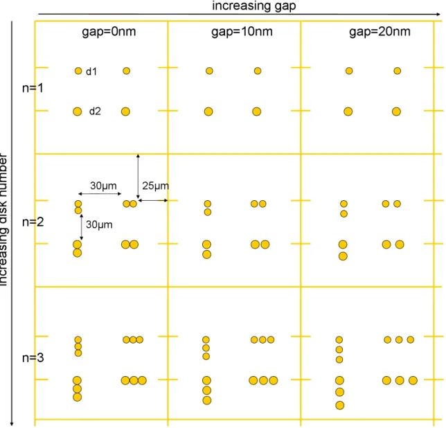
The fifth and last chapter finally addresses the study of more sophisticated nanoobjects. We will present an extensive study of the scattering characteristics of various chains of nanodisks with different disk numbers and disk spacings. In this context, we will demonstrate that depending on the illumination configuration, different modes can be excited, resulting into different characteristics of the scattered (far) field which can be imaged via holography. Furthermore, we will demonstrate that a nanodisk chain can be seen as a nanoantenna structure due to its ability to strongly scatter light in one direction. In the second part of this chapter we will apply the technique of photothermal holography to study the heating and the coupling of these chains. Lastly, a preliminary study on pairs of gold triangles will reveal the appearance of resonant modes dependent on the width of the triangles.
Chapter 1
Plasmonics and Optical Antennas
Table of contents
1.1 A Short Introduction to Plasmonics . . . . 3
1.1.1 Surface Plasmon Polaritons . . . 4
1.1.2 Localized Surface Plasmons . . . 5
1.1.3 Single Particle Plasmon Resonances - The Quasi-Static Approx-imation . . . 6
1.1.4 Theoretical Considerations beyond the Quasi-Static Limit: Re-tardation Effects . . . 8
1.2 Optical Antennas . . . . 9
1.2.1 Properties of Optical Antennas . . . 9
1.2.2 Nanoantenna Geometries . . . 10
1.2.3 Applications of Optical Antennas - State of the Art . . . 12
“· · · by chance I was keeping one of the metal plates at a very high distance from the ground while the other one was in the ground. Using this arrangement the signals became so strong that I was able to transmit up to one kilometer away. From that moment on the progress increased enormously. The plate at the top - the antenna - was raised more and more and the other one - the terra - was buried in the ground.”
Guglielmo Marconi (1895)
“· · · is it possible, for example to emit light from a whole set of antennas, like we emit radio waves from an organized set of antennas to beam the radio programs to Europe? The same thing would be to beam the light out in a definite direction with very high intensity.” Richard Feynman (1959)
1.1. A Short Introduction to Plasmonics 3
1.1
A Short Introduction to Plasmonics
I
n the last decade, the trend towards nanoscience and nanotechnology increased rapidly.This trend is motivated by the fact that as we move to smaller scales the underlying physical laws change from macroscopic to microscopic and new physical effects become prominent that may be exploited in future technological applications (Novotny and Hecht 2006). The expanding demand for smaller and faster optical and electronic devices has considerably increased the interest in nano-optics, a research field that covers all types of studies that include optical interactions with matter on a subwavelength scale.One of the major emerging fields from nano-optics is plasmonics which is based on the interaction processes between electromagnetic radiation and conduction electrons at conducting interfaces or in conductive nanostructures, called surface plasmon polaritons and localized surface plasmons. Whereas the former are created at a dielectric-conductive interface, the latter are excited in conductive nanostructures. Although all conductive materials support plasmons, the noble metals silver and gold are mostly associated with the field of optical plasmonics since their plasmon resonances lie close to the visible region of the spectrum, and they enable relatively low losses in this range, which allows plas-mon excitation by standard optical sources and methods. One of their most interesting properties is their ability to enhance and confine the electric field in 1, 2 or 3 dimen-sions of sub-lambda size. The field of plasmonics is based on exploiting plasmons for a variety of tasks, by designing and manipulating the geometry of metallic structures, and consequently their plasmon-resonant properties.
The strongly increasing research in the field of plasmonics in the last decade can be attributed to several factors. The increasing development of state of the art lithographic and chemical methods allow the fabrication of a wide variety of well defined nanoparticles and complex nanostructures. This has opened the possibility to engineer the plasmon response on a nanoscale. This control opens completely new possibilities in materials sci-ence, communications, biochemistry and medicine (Pelton, Aizpurua, and Bryant 2008). Furthermore, the modelling and simulation techniques of the optical response of complex nanostructures have been greatly expanded. Hence, experimental observations can be verified by comparing to theoretical predictions. This interplay enables an optimization of the studied nanostructures and their properties.
Another factor that has supported the rise of research in plasmonics is the significant progress accomplished in developing experimental techniques for the study of plasmonic structures. Nowadays, measurements of optical absorption and scattering spectra of single nanoparticles are feasible, scanning near-field optical microscopy enables the spatial char-acterization of the near-field of a large variety of plasmonic nanostructures, and ultrafast time-scales can be accessed to probe the dynamics of plasmonics.
to Roman times, when metallic nanoparticles were used for the staining of glass. The most famous and most ancient example is the fourth-century Lycurgus cup from the British museum, whose glass looks green in reflected light, but ruby red in transmitted light. Those colours are complementary evidence that there is little optical loss inside the glass. Such colloidal suspensions of gold, silver and other metals have been widely used in stained glass since the Middle Ages. Depending on the particle sizes, transmission through a silver colloid can yield yellow light and transmission through gold ruby red. Metallic nanoparticles transmit light with an intensity that strongly depends on the incident and viewing angles. The magnificent coloured light from stained glass of the Sainte Chapelle in Paris is assumed to be largely due to the plasmonic resonances (Stockman 2011). The mathematical foundation of these particle plasmons was established by Mie in 1908.
Historically, the mathematical description of the surface plasmon modes was established in the early 20th century when Sommerfeld and Zenneck studied the propagation of ra-dio waves along a surface of a conductor of finite conductivity in the context of wireless telegraphy (Sommerfeld 1899; Sommerfeld 1909; Zenneck 1907). These early investiga-tions focused on frequencies much lower than that of visible light. The phenomenological difference of plasmonic surface waves and plane electromagnetic waves in free-space is however very small. Around the same period, Wood studied the reflection of visible light at metallic gratings and noted the observation of “anomalous” intensity drops in spec-tra (Wood 1902). This phenomenon was later theoretical described by Fano (Fano 1941). Finally in the 70s, Kretschmann and Raether realized the excitation of Sommerfeld’s surface waves with visible light using prism coupling (Kretschmann and Raether 1968; Kretschmann 1971). With this a unified description of surface plasmon polaritons was established (Maier 2007).
In the following, we will elucidate the basic physics of plasmonics by describing surface plasmon polaritons and the localized surface plasmons. For a better understanding of the physics and its consequences of the latter we will introduce the quasi-static approximation and discuss briefly the impact of retardation effects.
1.1.1
Surface Plasmon Polaritons
Surface plasmon polaritons (SPP) are electromagnetic excitations propagating as a longi-tudinal wave at the interface between a dielectric and a conductor. Their field intensities fall off exponentially in the direction normal to the surface, the wave is therefore evanes-cent. Those surface waves arise via the coupling of the electromagnetic fields to oscillations of the conductor’s electron plasma. The waves are transverse-magnetic (TM), i.e. their magnetic field is perpendicular to their wave vector ~kSP P and in the plane of interface.
The dispersion relation of SPPs propagating at the interface between a metal of dielec-tric function ε(ω) and a dielecdielec-tric half space, described via the dielecdielec-tric function εmedium,
1.1. A Short Introduction to Plasmonics 5 is given by (Maier 2007): kSP P = ω c s ε · εmedium ε+ εmedium (1.1) where ω denotes the angular frequency and c the velocity of light. Equation 1.1 reveals that the wave vector of a SPP is always higher than that of an electromagnetic wave of the same frequency propagating in the adjacent dielectric alone. Because the wave vector in the plane must be conserved - a condition equivalent to conservation of the in-plane component of linear momentum - it is impossible to excite a SPP and fulfil the phase matching condition at an interface by an electromagnetic wave propagating in the dielectric. A SPP cannot radiate into the dielectric, therefore, the SPPs are also called “dark waves” (Stockman 2011). SPPs, however, can be excited using the so-called Otto or Kretschmann geometry in which a prism made of a dielectric material with higher optical index increases the k-vector to allow the excitation of SPPs. In the Kretschmann configuration, for example, the excitation light passes through a prism and is incident on the lower interface of a thin metal film. The medium above the metal is dielectric and typically air. The evanescent field of the light wave at the upper interface of the metal is then able to excite a SPP wave under total internal reflection condition.
1.1.2
Localized Surface Plasmons
Localized surface plasmons, or surface plasmons (SP), are non-propagating excitations of the conduction electrons of metallic nanostructures coupled to the electromagnetic field. These modes arise from the scattering of a small, sub-wavelength metal nanoparticle in an oscillating electromagnetic field. The curved surface of the particle exerts an effective restoring force on the driven electrons, so that a resonance can arise, leading to field amplification both inside and in the near-field zone outside the particle. This resonance is called the localized surface plasmon resonance. The sub-wavelength size of the particle has also the consequence that plasmon resonances can be excited by direct light illumination without having to fulfil the phase-matching condition, in contrast to propagating surface plasmons.
To first approximation, the electrons of the metal nanoparticle move freely and, driven by an external light’s electric field, are periodically displaced with respect to the lattice ions. This displacement creates charges with opposite signs at opposite surfaces. Because these charges attract each other, they create also restoring forces. The result is an electron oscillator, whose quantum is called surface plasmon and whose frequency is determined by the restoring force and effective mass of the electron. The frequency of the SPs depends on many factors, notably the physical properties of the metal and of the surrounding dielectric material, the size and shape of the nanoparticle.
1.1.3
Single Particle Plasmon Resonances - The Quasi-Static
Approximation
The oscillations of localized surface plasmons originate from the characteristic dielectric response of metals at optical frequencies. At resonance the polarizability is resonantly increased resulting in enhanced scattering, absorption and near-field intensities.
A full theoretical treatment of the interaction of a nanoparticle with an electromagnetic wave is beyond our scope. For a better understanding of the underlying physics let us introduce the quasi-static approximation, which is a simple model describing well the main results from such an interaction in first approximation.
Figure 1.1– Sketch of the model of the quasi-static approximation. A homogeneous sphere is placed into an external electrostatic field Eext.
The response of sub-wavelength sized particles to a plane-wave illumination can be analysed using the quasi-static approximation which is illustrated in Fig. 1.1. This model neglects retardation, i.e. effects due to self-induction of electromagnetic fields, by consid-ering only a region in space which is much smaller than the wavelength of light, so that the electromagnetic phase is constant throughout the region of interest. Consequently, the quasi-static approximation is only valid for particles that are smaller in size than the skin depth ds of the metal. 1 For small spherical particles with a radius much smaller
than the wavelength, this condition is fulfilled. We consider now a sphere of polarizable material with a radius R and a dielectric constant ε, embedded in a medium with di-electric constant εmedium, under the influence of a static electric field Eext. The external
field induces a dipole moment in the sphere. The polarizability is written as (Bohren and Huffman 1983):
α= 4πR3ε
0 ε − εmedium
ε+ 2εmedium
(1.2) It is evident from Eq. (1.2) that in vacuum (i.e. εmedium = 1) this expression exhibits a
resonance when the real part of ε approaches −2. Replacing the static dielectric constant
1The skin depth is the extent to which a field penetrates the metal surface and is given by d
s =
1.1. A Short Introduction to Plasmonics 7
ε with the wavelength dependent form ε(ω) = ε1(ω) + iε2(ω), the dielectric function of
a noble metal, for example gold and silver, fulfils the resonance condition ε1(ω) → −2
at visible frequencies. Hence, at resonance the real part of the denominator in Eq. (1.2) almost vanishes and causes a strongly increased induced dipole moment µP = α · Eext.
This in turn leads to enhanced scattering and local fields.
For nanoparticles with an elongated shape, the electron oscillation is non-isotropic and localized either along the principle axes or at the edges and corners of the nanoparti-cle, leading to an additional shape-dependent depolarization and splitting of the sur-face plasmon resonance into several modes (such as longitudinal or transverse modes for nanorods) (Lal et al. 2007).
The electrostatic theory for light scattering by sub-wavelength sized spherical particles has a relatively simple extension to ellipsoidal particles. In particular, we are interested in the scattering by disks and rods which can be described as spheroidal particles in a first approximation. A rod can de described by a prolate (cigar-shaped) particle, whereas a disk is approximately an oblate (pancake-shaped) particle. The polarizability αi of such
an ellipsoidal particle along the axis i is given by (Bohren and Huffman 1983): αi = V ε0 ε(ω) − εmedium
3 εmedium+ 3 Li[ε(ω) − εmedium]
(1.3) V is the particle’s volume and Li is a geometrical factor related to the shape of the particle
and given by Li = a1a2a3 2 ∞ Z 0 dq (a2 i + q) f(q) (1.4) where f(q) = q(q + a2
1)(q + a22)(q + a23). The ellipsoid is described by its semiaxis a1 ≤
a2 ≤ a3, specified by x 2 a2 1 + y2 a2 2 + z2 a2
3 = 1. The geometrical factors satisfy
3
P
i=1Li = 1, and for
a sphere L1 = L2 = L3 = 13.
A detailed analysis of the resonance position as a function of the aspect ratio (i.e. the ratio of the long axis radius to the short axis radius of the particle) using Eq. (1.3) shows that the resonance position depends approximately linearly on the aspect ratio: an in-creased aspect ratio leads to a red shifted resonance. Furthermore, the influence of the refractive index of the surrounding medium has to be considered as well. Increasing the refractive index leads to a red-shift of the resonance and a narrowing of its linewidth (Sön-nichsen 2001). This red-shift is due to the shielding of surface charges by the polarization of the embedding medium.
We have seen that the theory of scattering and absorption of radiation by a small sphere predicts a resonant field enhancement due to a resonance of the polarizability α in expression (1.2) if Re{ε(ω)} → −2 εmedium. The nanoparticle acts like an electric dipole
only for very small particles, provides a good approximation for particles of sizes below 100 nm in the visible or near-infrared frequency range.
For larger particles, where the quasi-static approximation is no longer valid due to sig-nificant phase changes of the driving field over the particle volume, an electrodynamic approach is required. Mie developed a complete theory of the scattering of electromag-netic radiation by spherical particles (Mie 1908). The approach of the Mie theory is to expand the internal fields and the scattered fields into a set of normal modes described by vector harmonics (Bohren and Huffman 1983; Kreibig and Vollmer 1995). The phys-ical consequences of the first-order corrections to the quasi-static approximation will be shortly examined in the following section.
1.1.4
Theoretical Considerations beyond the Quasi-Static Limit:
Retardation Effects
For large particles with sizes not negligible compared to the wavelength, the quasi-static approximation breaks down due to retardation effects. The effect of retardation of the exciting field over the volume in the particle leads to a shift in the plasmon resonance. Further, the retardation of the depolarization field inside the particle also leads to a shift in resonance (Meier and Wokaun 1983). For noble metals, the overall shift is towards lower energies, i.e. the dipole resonance position red-shifts with increasing particle size. Intuitively, this effect can be understood by considering that the distance between the charges at opposite interfaces of the particle increases with the particle size. This leads to a smaller restoring force and therefore a lowering of the resonance frequency (Maier 2007).
Another retardation effect that has to be taken into account is the reduction of ab-sorption (which is directly related to the imaginary part of ε(ω), i.e. Im{ε(ω)}), due to the increase of polarization. In order to account qualitatively for this effect, we have to consider the influence of radiation damping which leads to an attenuation in polariza-tion. Radiation damping is caused by a direct radiative decay of the coherent electron oscillations into photons (Kokkinakis and Alexopoulos 1972), and it is the main cause of the weakening of the strength of the dipole plasmon resonance as the particle volume in-creases (Wokaun et al. 1982). As a result, the influence of radiation damping countervails the increase of polarization in strength due to the reduction of absorption.
In summary, the plasmon resonance of particles beyond the quasistatic regime is damped by two competing processes: a radiative decay process into photons, dominating for larger particles, and a non-radiative process due to absorption.
1.2. Optical Antennas 9
1.2
Optical Antennas
The concept of optical antennas has its origin in near-field optics (Novotny 2007a; Bharad-waj et al. 2009; Biagioni et al. 2011) when, in 1928, Edward Synge proposed the use of a tiny gold particle for localizing optical radiation on a sample surface and thereby sur-passing the diffraction limit in optical imaging (Synge 1928). This particle can be viewed as an optical antenna, a structure that converts the energy of incident optical radiation into localized energy or vice versa, depending on whether the antenna occupies the role of a receiver or a transmitter.
Nanoantennas are the optical analogue of radio and microwave antennas. Since the wavelength is considerably lower, the size of the antenna must be reduced accordingly, which has only recently become feasible. They can be used to resonantly enhance light scattering (Greffet 2005; Mühlschlegel et al. 2005). Strictly speaking, antennas incorpo-rate a transducer or a source of energy, but in a broader sense, entirely passive structures are here also called nanoantennas.
Nanoantennas are of great interest since they allow unique control of absorption and emission at the nanometer scale: confinement of the electromagnetic field to sub-wavelength dimensions (Farahani et al. 2005), field enhancement (Zhang et al. 2010; Kühn et al. 2006) and directivity of the emitted light (Taminiau et al. 2007; Curto et al. 2010).
Optical antennas fulfil the same function as their radio analogues, but with properties that differ in important ways. At radio-frequencies, metals behave like perfect conductors, with a skin depth that is negligible compared to the size of the antenna. But at optical frequencies, the skin depth is on the scale of tens of nanometers, i.e. on the scale of the nanoantenna size, and the metal behaves like a plasma strongly coupled to incident light. As a result, the antenna geometry scales with an effective wavelength that differs from the wavelength of the incident light (Novotny 2007b) in contrast to the size dependence of analogue antennas. Moreover, optical antennas can take various unusual forms and their properties may be strongly shape and material dependent due to their surface plasmon resonances.
1.2.1
Properties of Optical Antennas
Nanoantennas can be characterized using the same terminology as used for radio-frequency (RF) antennas. In the following, we briefly introduce the principle properties describing an antenna.
The function of an antenna is to enhance the transmission efficiency from the trans-mitter to the receiver. This enhancement can be achieved by increasing the total amount of the radiation released by the transmitter. This property is described by the antenna
efficiency: εrad = Prad P = Prad Prad+ Ploss (1.5) where P is the total power dissipated by the antenna, Prad is the radiated power and Ploss
is the power dissipated into heat.
The directivity D is a measure of an antenna’s ability to concentrate radiated power into a certain direction. It corresponds to the angular power density p(θ, φ) relative to an isotropic radiator and is expressed by:
D(θ, φ) = 4π Prad
p(θ, φ) (1.6)
When the direction (θ, φ) is not explicitly stated, one usually refers to the direction of maximum directivity, i.e. Dmax = (4π/Prad) max{p(θ, φ)}. The combination of antenna
efficiency and directivity results into the antenna gain: G= 4π
P p(θ, φ) = εrad D (1.7)
Since perfectly isotropic radiators do not exist in reality, it is more convenient to use the relative gain by referring to an antenna of a known directional pattern. For this description a dipole antenna is normally used as a reference because of its relative simple radiation pattern. Recently, Huang et al. characterized the relative gain of coupled gold antenna pairs using the dipole-like scattering from a single particle as reference (Huang et al. 2008).
Radio wave antennas have strict design rules that relate to the wavelength of incident radiation. However, at optical frequencies these rules are no longer valid, the antenna responds to an effective wavelength which is reduced compared to the incident wavelength. The effective wavelength λef f is related to the incident wavelength λ by the wavelength
scaling relation derived by Novotny (Novotny 2007b): λef f = n1+ n2 ( λ
λP
) (1.8)
where λP is the plasma wavelength of the metal and n1 and n2 are constants depending
on the geometry and dielectric parameters of the antenna.
1.2.2
Nanoantenna Geometries
During the last years many different types of nanoantennas have been proposed. Here, we would like to present some geometries that have been fabricated and investigated experimentally.
1.2. Optical Antennas 11
Single Nanoparticles One of the simplest structures are single nanospheres and nanorods.
In fact, the use of a single nanoparticle as an antenna has already been proposed by Synge as we have noted earlier. Synge’s nanoparticle takes freely propagating radiation and lo-calizes it on a sample which has the role of the receiver. Since then, single nanoparticles have been successfully applied to enhance the sensitivity of fluorescence and Raman spec-troscopy at a single molecular level (Biagioni et al. 2011; Anger et al. 2006; Kühn et al. 2006; Rogobete et al. 2007; Mohammadi et al. 2008).
Coupled Nanoparticles Coupled nanoparticles can act as optical antennas: they
cou-ple efficiently in the near-field to photon emitters to enhance their interaction with the far-field. Nanostructures composed of two coupled nanospheres have been proposed as the analogue of RF Hertzian dipole antennas (Alu and Engheta 2008) and are expected to have a high radiation efficiency due to the reduced density inside the spheres. For such structures it is important to tune efficiently the gap size. Recently, it has been demonstrated that the programmed assembly of DNA functionalized gold nanoparticles is a technique that allows to tune particle sizes and spacings (Bidault et al. 2008; Bonod et al. 2010) with a high accuracy. Furthermore, it has been shown that a pair of coupled metallic nanoparticles coupled to a dielectric microsphere builds a highly efficient optical antenna (Devilez et al. 2010a).
The coupling of two nanorods represent the analogue to half-wave RF antennas
(Mühlschlegel et al. 2005; Ghenuche et al. 2008; Pramod and Thomas 2008). Very recently Greffet et al. have introduced the concept of impedance for a nanoantenna (Greffet et al. 2010) which provides a practical tool for the design of nanoantennas.
Bowtie Nanoantennas Bowtie antennas are constituted of two triangles facing each
other tip-to-tip (Fromm et al. 2004; Schuck et al. 2005; Fischer and Martin 2008). The advantage of the bowtie antenna compared to a pair of nanorods, is that it efficiently suppresses the field enhancement at the outer ends of the structure. Furthermore, they are considered to have higher field enhancements in the gap because of a larger lightning-rod effect at the apex. In reality, however, this effect is limited by the radius of curvature at the apex. Bowtie antennas are applied to enhance molecular fluorescence (Farahani et al. 2005; Kinkhabwala et al. 2009), Raman scattering (Fromm et al. 2006) and for the light confinement beyond the diffraction limit when fabricated on the facet of a quantum-cascade laser (Yu et al. 2007).
Yagi-Uda Nanoantennas The optical analogue of a RF Yagi-Uda antenna has been
theoretical proposed (Li et al. 2007; Taminiau et al. 2008) and since then experimentally verified (Kosako et al. 2010; Curto et al. 2010). The main advantage of an optical Yagi-Uda antenna is its very good directivity. Its unidirectional response is appealing in terms of enhanced sensitivity for detection. Similarly to their RF counterparts, nanometer-sized
Yagi-Uda antennas consist of a resonant single-wire antenna (π/2 phase shift between the driving field and the induced charge oscillations) arranged between a reflector (phase shift > π/2) and a set of directors (phase shift < π/2). To this purpose, the inter-element distance is important to achieve the desired interference between direct and reflected radiation (Biagioni et al. 2011).
Periodic Grooves Surrounding a Nanoaperture An antenna design that caught
the attention of the nanoantenna community a couple of years ago (Lezec et al. 2002) is composed of a single nanoaperture surrounded by periodic grooves. The central nanoaper-ture reduces the sampling volume and enables single molecule analysis at high concen-trations with enhanced excitation and emission rates. The periodic grooves act like an antenna to further concentrate the electromagnetic energy at the central aperture and to control the directivity of the radiated light. This design merges the light localization from the nanoaperture with the extended near- to far-field conversion capabilities from the concentric grooves. Recently, full directional control of the fluorescence emission from molecules in water solution has been demonstrated by using an optical antenna made of a nanoaperture surrounded by a periodic set of shallow grooves in a gold film (Aouani et al. 2011).
1.2.3
Applications of Optical Antennas - State of the Art
When Mühlschlegel et al. demonstrated that a thin metallic rod resonantly enhances light emission (Mühlschlegel et al. 2005; Greffet 2005), their important discovery bridged the fields of electrical engineering and nano-optics and led to a rapid and exponential growth of the research in the domain of nanoantennas. Since then, manifold applications of nanoantennas have been reported, and the number of publications is still increasing. To give a short overview of the state of the art of nanoantennas, we would like to highlight some noteworthy and interesting applications of nanoantennas and the latest advances in research.
Wavelength Tuning We have seen that the characteristics of a nanoparticle are
gener-ally determined by its shape and material. In the case of an optical antenna composed of two or more particles, its characteristics are related to near-field interactions between the individual elements. Essentially such a structure remains a passive device. However, in order to enable a controlled optical exchange between two nanoscale objects, an external control of an antenna is highly desirable. In order to tune the near-field coupling exter-nally, it was shown that the length and the gap of an antenna can be tuned mechanically by precise nanomanipulation with the tip of an atomic force microscope (Merlein et al. 2008). However, this technique has the drawback of an inflexible tuning, that cannot be controlled over short time-scales.
1.2. Optical Antennas 13 In this context, Bouhelier and co-workers demonstrated an active control over antenna performances by an external electrical trigger. The authors used an anisotropic load medium to control the electromagnetic interaction between the individual elements of an optical antenna, resulting in a strong polarization and tuning response (Berthelot et al. 2009). Furthermore, they demonstrated by using this kind of external control, that the scattering diagram of an antenna can be externally adjusted (Huang et al. 2010).
Nano-Trapping Usually, for the trapping of nanoparticles high laser powers are needed
to create trapping forces large enough to overcome the Brownian motion. The advantage of the trapping of plasmonic structures is their capability to localize and enhance light in their near-field En. For a particle much smaller than the trapping light wavelength, the
trapping force is proportional to the gradient of |En|2. In the case of plasmonic structures
the electric field can be enhanced and spatially localized in an area much smaller than the diffraction limit. As a consequence, for similar illumination intensities, these structures generate much larger gradient forces than in the case of far-field trapping. Plasmonic trapping has been demonstrated experimentally by showing that cells and dielectric beads have been successfully trapped using a patterned surface with an illumination intensity much lower than that for far-field trapping (Righini et al. 2008). In another study the authors used a metallic nanoantenna to trap living bacteria for several hours with their orientation fixed by the asymmetry of the antennas (Righini et al. 2009).
Recently, Zhang et al. demonstrated the trapping of gold nanoparticles with diameters of 10 nm which correspond to the gap size of the used plasmonic antennas (Zhang et al. 2010). The analysis of the scattering spectra allowed the observation of trapping events due to a modification of the surface plasmon resonance. These studies draw the path towards a new generation of integrated devices to manipulate small specimen and observe nanoscopic processes.
Nano-Sensing The group around Giessen and Alivisatos demonstrated recently an
antenna-enhanced hydrogen sensing at the single-particle level (Liu et al. 2011). By placing a single palladium nanoparticle near the tip region of a gold nanoantenna, they detected the changing optical properties of the system on hydrogen exposure by dark-field microscopy. Their concept paves the road towards the observation of single catalytic processes in nanoreactors and biosensing on the single-molecule level.
Antennas in Near-Field Imaging In near-field optics the probe that is used to scan
the surface of a sample can be seen as an optical antenna. One of the first studies exploiting this concept involved attaching spherical gold nanoparticles, tuned to resonate at the wavelength of the incident light, to glass probes. It was found that scanning these resonant spheres close to single fluorescent molecules leads to an enhanced fluorescence and a reduction of lifetime (Anger et al. 2006; Kühn et al. 2006). It has been shown
that such a nanoprobe results into a spatial resolution of 50 nm. In order to achieve higher resolutions, antennas with strongly localized fields, smaller nanoparticles, sharper antenna ends or narrower gaps are required.
In this context, Taminiau et al. positioned a resonant nanoantenna, in form of a nanorod, at the end of a metal-coated near-field probe leading to an enhanced localized field near the antenna apex. This field was mapped with single fluorescent molecules which revealed a spatial localization of 25 nm (Taminiau et al. 2007).
Furthermore, the fabrication of bowtie antennas on the apex of silicon atomic-force mi-croscope tips has been reported (Weber-Bargioni et al. 2010). When excited at resonance these antennas enhance the local silicon Raman scattering intensity.
Antennas for Photodetection The application of optical antennas in photodetectors
is interesting since a nanoantenna increases the absorption cross-section. In the case of a photodetector it means that the light flux that impinges on the detector is increased. Thus, by using nanoantennas the size of a photodetector can be drastically reduced. Tang et al. experimentally demonstrated that the active volume of a germanium photodetector can be reduced to sub-lambda size using a Hertz dipole antenna, resonating in the near-infrared wavelength range, resulting into an enhanced detection sensitivity (Tang et al. 2008).
Recently, Knight et al. developed a structure composed of a metallic nanoantenna on a semiconductor surface which can be used as a polarization-specific light detector being highly compact and wavelength resonant (Knight et al. 2011). In this device, photons couple into the nanoantenna and excite resonant plasmons, which decay into energetic, so called “hot” electrons injected over a potential barrier at the nanoantenna-semiconductor interface, resulting in a photocurrent.
Directional Emission In the radio-frequency regime a typical antenna design for high
directivity is the Yagi-Uda antenna which consists of an array of antenna elements driven by a single feed element. It has been shown that by fabricating a corresponding array of nanoparticles, similar radiation patterns can be obtained in the optical regime (Li et al. 2007; Pellegrini et al. 2009; Dorfmüller et al. 2011). In this context, Kosako et al. presented the experimental demonstration of directional control of radiation from a nano-optical Yagi-Uda antenna composed of tuned gold nanorods (Kosako et al. 2010). Their results show clearly that the basic principles of RF antenna design can be applied to the optical regime.
Shortly after, the unidirectional emission of a single emitter, a quantum dot, has been successfully demonstrated by coupling the emitter to a nanofabricated Yagi-Uda an-tenna (Curto et al. 2010). The emitter is placed in the near-field of the anan-tenna so that the emitter drives the resonant feed element of the antenna. The resulting
lumines-1.3. Conclusion 15 cence of the quantum dot is highly directed into a narrow angular cone. Furthermore, the directionality can be controlled by tuning the dimensions of the antenna. These results demonstrate the potential of optical antennas to communicate light to, from and between nano-emitters to be used for quantum optical technologies, planar biochemical sensors, and light-harvesting and emission devices.
1.3
Conclusion
The rapidly growing research field plasmonics has yielded unique phenomena based on light-metal interactions that may give rise to new, useful applications and technologies, ranging from ‘light-on-a-chip’ to ‘lab-on-a-chip’ (Lal et al. 2007). Here, we gave a brief introduction into the physics of surface plasmons polaritons and particle plasmons.
Optical antennas emerged recently from near-field optics and since then have been widely studied as a tool to manipulate and control light at the nano-scale. We have presented the main parameters that are used to describe a nanoantenna, in analogy to ‘classical’ antennas working in the radio-frequency range. Several possible geometries of a nanoantenna have been discussed, and we gave an overview of recent advances in the research field of nanoantennas.
One of the most interesting parameters of an antenna is its directivity. In this context, we have presented two recent studies that measured the angular radiation pattern of nanoantennas of the Yagi-Uda type. The two groups used two approaches: One method consists of recording the antenna emission in the plane perpendicular to the antenna with a photodiode (Kosako et al. 2010). Another method is based on confocal microscopy in which the emission intensity distribution is imaged on the back focal plane of a high-NA objective (Curto et al. 2010). In the course of this work, we will show that holography as well has the capability of measuring angular scattering patterns. This is due to the simultaneous recording of both amplitude and phase in holography which therefore gives access to the three-dimensional information of the scattered field and thus, to the angular scattering spectrum of the hologram simply by calculating the scattered field’s Fourier transform.
Chapter 2
Digital Heterodyne Holography
Table of contents
2.1 Historical Overview . . . . 19 2.2 Principles of Holography . . . . 20 2.2.1 Off-Axis Holography . . . 23 2.3 Digital Holography . . . . 24 2.3.1 Numerical Holographic Reconstruction . . . 25 2.3.2 Phase Shifting Holography . . . 28 2.3.3 Digital Heterodyne Off-Axis Holography . . . 30 2.3.4 Experimental Setup of DHH . . . 32 2.4 Photothermal Heterodyne Holography . . . . 35 2.4.1 Experimental Setup of Photothermal DHH . . . 36 2.5 Frequency Domain Detection by Heterodyne Holography . . 37
2.5.1 Application 1: Frequency-Resolved Temperature Imaging of In-tegrated Circuits . . . 38 2.5.2 Application 2: Frequency Detection in the Brownian Regime of
Gold Nanorods . . . 45 2.5.3 Conclusion on Frequency Detection . . . 53 2.6 Conclusion on Digital Heterodyne Holography . . . . 53
“The future cannot be predicted, but futures can be invented.”
2.1. Historical Overview 19
I
n 1948 Dennis Gabor invented holography (Gabor 1948; Gabor 1949), a work for whichhe received the Nobel prize in Physics 23 years later. Holography is a method to record and reconstruct the amplitude and phase of a wavefield. A hologram is an interference pattern that is photographically or otherwise recorded, between the wavefield scattered from the object and the so called reference wave. A hologram is usually recorded on a flat surface, but contains information about the entire three-dimensional wavefield. This information is coded in form of interference patterns, usually not visible to the human eye due to the high spatial frequencies it contains. In “classical holography” the object wave is reconstructed by illuminating the hologram with the reference wave again. This wave reconstructed by passive means is indistinguishable from the original object wave. An observer recognizes a three-dimensional image with all effects of perspective and depth of focus (Schnars and Jüptner 2002; Schnars and Jüptner 2005).2.1
Historical Overview
In Gabor’s original setup, the axes of both the object wave and the reference wave are parallel. This in-line configuration leads to a reconstructed image, the real image, su-perimposed by the bright reconstruction wave and a second image, the so called “twin image”, or virtual image. In 1964 Leith and Upatnieks (Leith and Upatnieks 1962; Leith and Upatnieks 1964) improved this in-line holography by introducing an off-axis reference wave. By doing so, the two images and the reconstruction wave are spatially separated. In the late 1960s and early 70s the first steps towards digital holography were made by Goodman and Lawrence and the Yaroslavski group (Goodman and Lawrence 1967; Kronrod et al. 1972). They sampled optically enlarged parts of in-line and Fourier holo-grams recorded on a photographic plate. The digitized “conventional” holoholo-grams were reconstructed numerically.
In 1994 Schnars and Jüptner made a big step forward by developing the direct recording of Fresnel holograms with charged coupled device (CCD) cameras (Schnars and Jüptner 1994). The numerical recording allows the direct calculation of phase and amplitude. Schnars and Jüptner used the off-axis configuration which, however, has the drawback of a low spatial resolution of the CCD camera due to the off-axis angle which must be limited to few degrees. From then on, digital holography enabled full digital recording and processing of holograms, without any photographic recording as an intermediate step, and has nowadays many applications in a widespread range.
In 1997, Yamaguchi introduced phase-shifting digital holography, a method to circum-vent the restriction in the reconstructed image area caused by the off-axis setup (Yam-aguchi and Zhang 1997). In their proposed in-line configuration, the reference beam is phase shifted with respect to the object beam. Thus, the twin image is suppressed in computer reconstruction. In the year 2000, the Depeursinge group (Cuche et al. 2000)
developed a method to filter spatially the zero-order and eliminate the twin-image in dig-ital off-axis holography. In the same year, Le Clerc et al. presented a holography method based on heterodyne detection of the amplitude and phase (Le Clerc et al. 2000). In this technique the phase shift is achieved by frequency shifting the reference beam. They show that a frequency shift created by combining two acousto-optic modulators, results into a very accurate phase shift.
A couple of years ago a variant of the heterodyne holography scheme was proposed combining the properties of off-axis and phase-shifting holography (Gross and Atlan 2007). This technique enables to filter numerically the zero-order image alias and the technical noise of the reference. The authors demonstrated that the obtained sensitivity and signal-to-noise ratio (SNR) are excellent.
Outline
This chapter is structured as follows: Firstly, the basic principles of holography are dis-cussed. The process of hologram recording and hologram reconstruction is described, and the technique of off-axis holography is presented, a technique to separate the different diffraction orders. Then, digital holography is introduced, and we discuss the impact on the reconstruction process which is performed numerically. We present the method of digital heterodyne off-axis holography which achieves an excellent detection sensitivity for weak signals making it an ideal technique for the imaging of nanoobjects. In this context, we introduce the photothermal heterodyne holography, which proved recently its appli-cation to detect gold nanobeads under a photothermal modulation (Absil et al. 2010). Lastly, we show that the heterodyne technique gives access to the frequency domain by varying the heterodyne beating frequency. We present two applications. As a validation we measured the frequency components of the temperature variations in an integrated circuit. Furthermore, we applied this method to the detection of the frequency domain of gold rods in a Brownian regime.
2.2
Principles of Holography
Holography consists of two processes: the recording of the hologram and the hologram reconstruction. Since holography is based on the interference of two light waves, the light source must have a sufficient coherence length.
The general setup of holography is shown in Fig. 2.1. The coherent light source is split into two partial waves by a beam splitter. To record a hologram the object is illuminated by the first wave. The object scatters light that is reflected to the recording medium, e.g. a photographic plate, that is placed at a distance d from the object. The second wave, the so called reference wave, illuminates the light sensitive medium directly where it interferes