AEROSPACE AND MECHANICAL ENGINEERING DEPARTMENT UNIVERSITY OF LIÈGE
Sustainable Energy Conversion Through the
Use of Organic Rankine Cycles for Waste
Heat Recovery and Solar Applications.
in Partial Fulfillment of the Requirements for the Degree of Doctor of Applied Sciences
Presented to the Faculty of Applied Science of the University of Liège (Belgium) by
Sylvain Quoilin
Version 1.3, published in October 2011
© 2011 Sylvain Quoilin 〈►squoilin@ulg.ac.be〉
Licence. This work is licensed under the Creative Commons Attribution - No Derivative Works 2.5 License. To view a copy of this license, visit
►http://creativecommons.org/licenses/by-nd/2.5/ or send a letter to Creative Commons, 543 Howard Street, 5th Floor, San Francisco, California, 94105, USA. Contact the author to request other uses if necessary.
Trademarks and service marks. All trademarks, service marks, logos and company names mentioned in this work are property of their respective owner. They are protected under trademark law and unfair competition law.
The importance of the glossary. It is strongly recommended to read the glossary in full before starting with the first chapter.
Hints for screen use. This work is optimized for both screen and paper use. It is recommended to use the digital version where applicable. It is a file in Portable Document Format (PDF) with hyperlinks for convenient navigation. All hyperlinks are marked with link flags (►). Hyperlinks in diagrams might be marked with colored borders instead.
Navigation aid for bibliographic references. Bibliographic references to works which are publicly available as PDF files mention the logical page number and an offset (if non-zero) to calculate the physical page number. For example, to look up [Example :a01, p. 100-80] jump to physical page 20 in your
Abstract
This thesis contributes to the knowledge and the characterization of small-scale Organic Rankine Cycles (ORC). It is based on experimental data, thermodynamic models and case studies.
The experimental studies include:
1. A prototype of small-scale waste heat recovery ORC using an open-drive oil-free scroll expander, declined in two successive versions with major improvements.
2. A prototype of hermetic scroll expander tested on vapor test rig designed for that purpose.
The achieved performance are promising, with expander overall isentropic effectivenesses higher than 70% and cycle efficiencies comparable or higher than the typical efficiencies reported in the scientific literature for the considered temperature range.
New steady-state semi-empirical models of each component are developed and validated with the experimental data. The global model of the ORC prototype allows predicting its performance with a good accuracy and can be exploited to simulate possible improvements or alternative cycle configurations.
Dynamic models of the cycle are also developed for the purpose of evaluating
the system's reaction to transient conditions. These models are used to define and compare different control strategies.
The issues of cycle optimization and fluid selection are treated using the steady-state semi-empirical models. The thermodynamic optimization of such cycles is first demonstrated by practical examples. Furthermore, three different methods for fluid selection are proposed, investigated and compared. Their respective advantages and fields of application are described.
Finally, two prospective studies of small-scale ORC systems are proposed. The first one is a solar ORC designed for the rural electrification of remote regions in Africa. This prototype aims at competing with the photovoltaic technology, with the advantage of generating hot water as by-product.
The second prospective study deals with the recovery of highly transient heat sources. Advanced regulation strategies are proposed to address the practical issues of such systems. These strategies are compared with the state-of-the-art strategies and show a non-negligible potential of performance improvement.
Acknowledgments
I would like to thank Professor Vincent Lemort for his trust and his support during the whole period of this work. I wish to thank him for the numerous moments spent working together on practical and theoretical issues as well as for countless valuable discussions.
I am also grateful to professor Jean Lebrun, who gave me the opportunity to start this thesis and provided constructive advices along the work.
Thank you to the members of the Thesis Committee, Piero Colonna, Assaad Zoughaib, Georges Heyen, Philippe Ngendakumana and Pierre Duysinx for their valuable comments and constructive criticism.
A large part of this work would not have been possible without the trust of colleagues from foreign laboratories, namely Matthew Orosz, Andreas Schuster, Richard Aumann and their respective teams. They allowed me to gain valuable experience and know-how and warmly welcomed me to stay in their labs.
Special thanks goes to Stéphane Bertagnolio and all the members of the Thermodynamics Laboratory for their help and availability, but above all for their friendship and the great moments spent together during these four years. Furthermore, I want to thank my family and my friends for their support and encouragements throughout my studies. Last but not least, special thanks to Jessica Schrouff for her unwavering support, for the proofreading and for the multiple comments and advices to improve this thesis.
Table of contents
► Abstract... v ► Acknowledgments...vii ► Table of contents...ix ► Nomenclature...xiii ► Chapter 1: Introduction...1 ► Chapter 2: The Organic Rankine Cycle ...1►1 Introduction...1
►2 Applications...2
►2.1 Biomass combined heat and power...2
►2.2 Geothermal energy...4
►2.3 Solar power plants...5
►2.4 Heat recovery on mechanical equipment and industry processes 7 ►2.5 Heat recovery on internal combustion engines...7
►3 Comparison with the steam Rankine Cycle...9
►4 Expansion machines...12
►4.1 Turbomachines...12
►4.2 Positive displacement expanders...13
► Chapter 3: Experimental setups...1
►1 Introduction...1
►2 ORC test bench...3
►2.1 Description...3
►2.2 Measurements ...7
►2.3 Achieved performance...9
►3 Improved ORC test bench...12
►3.1 Description...12
►4 Expander test rig...18
►4.1 Description of the test rig...18
►4.2 Measurement devices...21
►4.3 Overall measured performance...21
►4.4 Impact of oil mass fraction on performance...24
►5 Conclusions...25 ► Chapter 4: Modeling...1 ►1 Introduction...1 ►2 Steady-state modeling...2 ►2.1 Models...2 ►2.2 Heat exchangers...12 ►2.3 Pump... 18 ►2.4 Cycle model...19 ►2.5 Model exploitation...21 ►3 Dynamic models...27
►3.1 Heat exchangers model...27
►3.2 Pump/expander models...35
►3.3 Liquid receiver model...35
►3.4 Valve model...36
►4 Conclusions...37
► Chapter 5: Fluid selection and cycle optimization...1
►1 Introduction...1
►2 Thermodynamic optimization...4
►3 Working fluid selection: The screening approach...8
►4 Working fluid selection: The operating map approach...11
►4.1 Limitations of volumetric expanders...11
►4.2 Limitations of the turbine technology...12
►4.3 Operating maps...15
►5 Working fluid selection: The thermoeconomic approach...18
►5.1 Considered WHR ORC...18
►5.2 Considered Working fluids...19
►5.4 Thermodynamic optimization ...22 ►5.5 Thermoeconomic optimization ...23 ►5.6 Discussion ...26 ►6 Conclusions...27 ► Chapter 6: Case studies...1
►1 Prospective study n°1: Solar ORC...1
►1.1 Introduction...1
►1.2 System description...2
►1.3 Modeling...4
►1.4 System performance and fluid comparison...10
►1.5 Conclusions...17
►2 Transient Waste Heat Recovery Organic Rankine Cycle...18
►2.1 Introduction...18
►2.2 System description and methodology...18
►2.3 Dynamic model...20
►2.4 Control strategy...22
►2.5 Simulation results...26
►2.6 Comparison between control strategies...28
► Chapter 7:
Conclusions...1 ►A Experimental Data...V
►B Adaptation of a hermetic scroll compressor in expander mode... VII ►C Polynomial laws...XI
►D Steady-state moving-boundaries heat exchanger model...XIII
►E Display of the simulation results...XVII
►F Numerical issues in dynamic heat exchanger models...XIX
►G Compounding two scroll expanders in series...XXV ► Bibliography...XXIX
Nomenclature
A
area, m²AU
heat transfer conductance, W/Kb
corrugation depth, mBo
boiling number,Bo= ˙Q/( A G i
fg)
c
specific heat, J/(kg K)Co
convection number, Co=ρg/ρl((1−x )/ x)0.5d
diameter, mD
h hydraulic diameter, mFr
froude numberFr=G
2/(ρ⋅
g⋅D
h)
G
mass velocity, kg/m²sh
heat transfer coefficient, W/m²Kh
specific enthalpy, J/(kg K)i
fg enthalpy of vaporization, J/kgk
conductivity, W/m KK
p proportional gain,-L
length, mM
mass, kg˙
M
mass flow rate, kg/sN
number of nodes,-N
s specific speed, radN
p number of plates,-N
rot rotating speed, rpmNu
Nusselt number,Nu=h D
h/
k
p
pressure, PaP
r Prandtl number,Pr=μ Cp /k
pinch
pinch point value, K˙
Q Heat power, W
˙q
linear heat flux, W/m-r
v ,in internal builtin volume ratio,-s
specific entropy, J/(kg K)S
beam beam solar insolation, W/m²t
time, sT
temperature, °CT
torque, N mU
heat transfer coefficient, W/(m² K)U
tip speed, m/sv
specific volume, m³/kgV
velocity, m/sV
volume, m³V
s swept volume, m³˙
V
volume flow rate, m³/sw
specific work, J/kgW
width, m W relative speed, m/s˙
W
power, Wx
vapor quality,-x
axial distance, mX
capacity fraction, -Greek symbolsα
absorptivityα
proportionality factorε
effectiveness ε emissivityΔ
differential η efficiency ρ density, kg/m³ ρ reflectivity,-ϕ
filling factor,-τ
transmittance-τ
time constant, sξ
penalty factorSubscripts and superscripts
abs Absorber ad Adapted amb Ambient cal Calorimeter calc Calculated cd Condenser cf Cold fluid col Collector el Electrical em Electromechanical ev Evaporator ex Exhaust exp Expander f Working fluid i Relative to cell i in Internal hr Heat recovery
htf Heat transfer fluid
hx Heat exchanger l Liquid meas Measured n Nominal opt Optical pp Pump pred Predicted r Refrigerant rec Recuperator ref Reference s Isentropic, Swept sh Shaft
sf Secondary fluid su Supply tot Total tp Two-phase v Vapor, volume w wall
2 turbine nozzle exhaust
3 turbine rotor exhaust
Acronyms
BWR Back Work Ratio
CHP Combined Heat and Power
CS Control Signal
CSP Concentrating Solar Power
GDP Gross Domestic Product
GHG Greenhouse Gases
GWP Global Warming Potential
HCE Heat Collection Element
HVAC Heating, Ventilation, and Air Conditioning ICE Internal Combustion Engine
IPCC Intergovernmental Panel on Climate Change ODP Ozone Depleting Potential
ORC Organic Rankine Cycle
PV Photovoltaïc
SIC Specific Investment Cost TIT Turbine Inlet Temperature
VC Volume Coefficient
Chapter 1:
Introduction
Modern technology Owes ecology An apology. Alan M. EddisonEnergy access is a fundamental parameter for human development. Institutions such as the World Bank, the United Nations or the European Union consider energy as a key-element for promoting or improving base services such as lightning, drinking water access, health services, education or communications.
The economic development stated in a number of areas in the world over the last century has involved an important growth in energy consumption. Unfortunately, this growth has been mainly covered by the use of fossil fuels, motivated by economic considerations. Other factors such as atmospheric pollution, limited oil resources and national energy dependence were not properly taken into account.
In its first report in 2007, the IPCC formulated the following statement: “Most
of the observed increase in global average temperatures since the mid-20th
century is very likely due to the observed increase in anthropogenic greenhouse gas concentrations.” According to the different scenarios the
average earth temperature should rise between 2 to 4°C before the end of the century, with dramatic consequences such as the rise of sea levels, higher drought occurrences and desertification, higher frequency of natural disasters, negative impact on biodiversity, etc.
84% of the greenhouse gases emissions are attributable to the energy sector, mainly in the form of carbon dioxide emissions (Quadrelli & Peterson, 2007). These emissions are mainly due to industrialized countries: the ten first emitting countries generate two thirds of the world emissions. It can be feared that the actual development of least-industrialized countries will be accompanied by a dramatic increase in CO2 emissions.
Today, a good correlation exists between gross energy consumption and GDP, literacy rate, infant mortality and fertility (Jones & Thompson, 1996). However, more and more voices are being heard, calling for a decoupling between economic growth and resource consumption (Jackson et al., 2011). This decoupling can only be achieved by massive investments in the R&D effort for sustainable energy conversion technologies and by promoting energy
efficiency policies. Massive technology transfers will also be required to ensure a cleaner development of countries with an emerging economy.
According to the EU 2050 Roadmap (European Climate Foundation, 2010), greenhouse gases emissions could be cut by 80% in 2050. This pathway involves the following modifications of the current energy system:
1. A decrease in the energy intensity of buildings (minus 950 TWh/year by 2050) and industry (minus 450 TWh/year).
2. A shift from fossil fuels towards electricity, e.g. for transportation and space heating.
3. Clean power generation by a massive shift towards renewable energies, among which 25% of wind energy, 19% of PV, 5% of CSP, 12% of biomass, 2% of geothermal, 12% of large hydro.
4. A reinforcement of the grid capacity and inter-regional transmission lines to absorb daily and seasonal fluctuations.
Amongst the proposed solutions to fulfill these objectives, the Organic Rankine Cycle (ORC) technology can play a non-negligible role, in particular for the objectives 1 and 3:
➢ It can have a beneficial effect on the energy intensity of industrial processes, mainly by recovering waste heat (i.e. heat that is otherwise lost).
➢ It can have a positive effect on building consumptions, e.g. using CHP systems.
➢ It can be used to convert renewable heat sources into electricity. This mainly includes geothermal, biomass and solar sources (CSP).
➢ During the shifting transition towards electric vehicles, it can be used to increase the well-to-wheel efficiency by waste heat recovery on the exhaust gases, on the EGR and on the engine coolant.
The Organic Rankine Cycle involves the same components as a conventional steam power plant (a boiler, a work-producing expansion device, a condenser and a pump). However, the working fluid is an organic component characterized by a lower ebullition temperature than water and allowing power generation from low heat source temperatures.
The success of the ORC technology can be partly explained by its modular feature: a similar ORC system can be used, with little modifications, in conjunction with various heat sources. Moreover, unlike conventional power cycles, this technology allows for local and small scale power generation.
Today, Organic Rankine Cycles are commercially available in the MW power range. However very few solutions are actually suitable for the kW scale.
This work aims at contributing to the development of the ORC technology, mainly in the small-scale power range. It is organized as follows:
Chapter 2 summarizes the state of the art of the ORC technology. The main applications are described, with their practical limitations, the range of competiveness, the practical design of the cycle, the typical efficiencies and temperature levels, etc.
Chapter 3 describes the experimental studies carried out on ORC prototypes and their components. Special attention is paid to the expander technology, since it is a key component for the efficient use of small-scale ORCs.
Chapter 4 describes the sizing and simulation models developed in the scope of this work and required for simulating and optimizing different types of ORC cycles. These models are validated using the experimental results of Chapter 3.
Chapter 5 takes profit of the acquired practical experience (Chapter 3) and of the developed models (Chapter 4) to propose an optimization methodology for such cycles. A thermodynamic optimization method is described and three fluid selection methods are proposed and compared.
Chapter 6 illustrates how the developed steady-state and dynamic models can be used to evaluate the performance of prospective small-scale ORC systems. A transient WHR system and a CSP system are evaluated.
Chapter 2:
The Organic Rankine Cycle
Summary. The Organic Rankine Cycle (ORC) is a well known technology since the early 70’s. A large amount of ORC power plants have been built, mainly for geothermal, waste heat recovery and combined heat and power applications. This technology shows a number of advantages over the traditional steam Rankine cycle, making it more profitable for power plants with a limited electrical output power (typically lower than 1 MWe), despite a lower efficiency. The optimization of the ORC is quite different from that of the steam cycle, mainly because of the heat source temperature limitation, and because there is usually no constraint regarding the vapor quality at the end of the expansion. This chapter presents an overview of the current state of the art in the ORC technology and exposes the main target applications.
1 Introduction
The particularity of the Organic Rankine Cycle (ORC) over the traditional Rankine cycle lays in the working fluid: an organic component is used instead of water. This organic compound is typically a refrigerant, a hydrocarbon (butane, pentane, hexane, etc.), a silicon oil, a perfluorocarbon... Its boiling point is lower than that of water, which allows recovering heat at a lower temperature than in the traditional steam Rankine cycle. Its thermophysical properties differ from that of water in a number of aspects (further discussed in section 3), which has practical implications on the design of the Organic Rankine Cycle.
Organic Rankine Cycles have been studied both theoretically (Davidson, 1977, Probert et al., 1983) and experimentally (Monahan, 1976) as early as in the 70s, with reported efficiencies usually below 10% for small-scale systems. Experimental studies generally involved the use of vane expanders (Badr et al., 1990, Davidson, 1977) and high Ozone Depleting Potential (ODP) refrigerants such as R11 or R13.
The first commercial applications appeared in the late 70s and in the 80s with medium-scale power plants developed for geothermal and solar applications. Nowadays, more than 200 ORC power plants are identified, with over 1800 MWe installed, and this number is growing at a faster pace than ever before. Most of the plants are installed for biomass CHP applications, followed by
geothermal plants and by WHR plants. It should however be noted that the first application in terms of installed power is geothermy (Enertime, 2011). The layout of the Organic Rankine Cycle is somewhat simpler than that of the steam Rankine cycle: there is no water-steam drum connected to the boiler, and one single heat exchanger can be used to perform the three evaporation phases: preheating, vaporization and superheating. The variations on the cycle architecture are also more limited: reheating and turbine bleeding are generally not suitable for the ORC cycle, but a recuperator can be installed as a liquid preheater between the pump outlet and the expander outlet, as illustrated in Figure 1.
The basic cycle is very similar to the traditional steam cycle: the organic working fluid is successively pumped, vaporized, expanded and then condensed. The cycle with recuperator takes profit of the residual heat after the expansion to preheat the liquid after the pump. This operation allows reducing the amount of heat needed to vaporize the fluid in the evaporator.
2 Applications
2.1 Biomass combined heat and power
Biomass is widely available in a number of agricultural or industrial processes such as wood industry or agricultural waste. It is best used locally for two main reasons : (1) the energy density of biomass is low compared to that of fossil fuels, which increases transportation costs; (2) heat and electricity demand are usually available on-site, which makes a biomass plant particularly suitable in the case of off-grid or unreliable grid connection. Local generation leads to smaller scale power plants (<1-2 MWe) which excludes traditional steam cycles that are not cost-effective in this power range.
The working principle of such a cogeneration system is described in Figure 2 and Figure 3: heat from the combustion is transferred from the flue gases to
Figure 1: Working principle of an ORC cycle with (right) and without (left) recuperator
the heat transfer fluid in two heat exchangers, at a temperature varying between 150 and 320°C. The heat transfer fluid (thermal oil) is then directed to the ORC loop to evaporate the working fluid, at a temperature slightly lower than 300°C. The evaporated fluid is then expanded, passes through the recuperator to preheat the liquid and is then condensed at a temperature around 90°C. The condenser is used for hot water production.
The efficiency of power generation with ORCs is lower than that of traditional steam cycles, and generally decreases for small scale units. This is statement is partly explained by their simpler design and lower cost. Heat demand is therefore a prerequisite to increase the overall plant energy conversion efficiency. This heat demand can be fulfilled by industrial processes (such as wood drying) or space heating. Plant load can be controlled either by on-site heat demand, or by maximizing power generation. The latter solution involves wasting the additional heat but has the advantage of increasing the annual full load operating hours.
Figure 2: Energy fluxes in a biomass CHP ORC system
Figure 3: Working principle of a biomass CHP ORC system
For the particular example of Figure 2, although the electrical efficiency of the CHP system is quite low (18%), the overall efficiency of the system is 88% which is much higher than centralized power plants, in which most of the residual heat is lost.
In order to reduce heat losses in the flue gases, these gases must be cooled down to the lowest possible value, as long as the acid dew point is not reached. To achieve this, two heat transfer loops are used: a high temperature loop and a low temperature loop. The low temperature loop is installed after the high temperature one on the flue gases to reduce their outlet temperature (Figure 3).
The main competing technology for electricity generation from solid biofuels is biomass gasification: In this technology, biomass is transformed into a synthetic gas composed mainly of H2, CO, CO2, CH4. This synthetic gas is
treated and filtered to eliminate solid particles, and is finally burned in an internal combustion engine or in a gas turbine.
When comparing the technology and the costs of Biomass CHP using an ORC with gasification, it can be showed that gasification yields higher investment costs (about 75%) and higher operation and maintenance costs (about 200%). On the other hand, gasification shows a higher power-to-thermal ratio, which makes its exploitation more profitable (Rentizelas et al., 2009). It should also be noted that ORC is a well-proven technology, while gasification plants actually in operation are mostly prototypes for demonstration purpose.
2.2 Geothermal energy
Geothermal heat sources are available over a broad range of temperatures, from a few tens of degrees up to 300°C. The actual technological lower bound for power generation is about 80°C: below this temperature conversion efficiency becomes too small and geothermal plants are not economical. Table 1 indicates the potential for geothermal energy in Europe and shows that this potential is very high for low temperature sources.
Temperature MWth MWe 65-90°C 147736 10462 90-120°C 75421 7503 120-150°C 22819 1268 150-225°C 42703 4745 225-350°C 66897 11150
Table 1: Potential for geothermal energy in Europe for different heat source temperature ranges (Data source: (Karytsas, 2007))
To recover heat at an acceptable temperature, boreholes must generally be drilled in the ground, for the production well and for the injection well (cfr. Figure 4). The hot brine is pumped from the first one and injected in the second one at a lower temperature. Depending on the geological configuration, boreholes can be several thousands meters deep, requiring several months of continuous work. This leads to a high share of the drilling in
the investment cost (up to 70%) of a geothermal ORC plant (Kranz, 2007). Low-temperature geothermal ORC plants are also characterized by a relatively high auxiliary consumption: the pumps consume from 30 up to more than 50% of the gross output power (Frick, 2009). The main consumer is the brine pump that has to circulate the brine on large distances and with an important flow rate. The working fluid pump consumption is also higher than in higher temperature cycles, because the ratio between pump consumption and turbine output power (“back work ratio”) increases with a decreasing evaporating temperature.
Higher temperature (>150°C) geothermal heat sources enable combined heat and power generation: the condensing temperature is set to a higher temperature (e.g. 60°C), allowing the cooling water to be used for district heating. In this case, the overall energy recovery efficiency is increased, but at the expense of a lower electrical efficiency.
2.3 Solar power plants
Concentrating solar power is a well-proven technology: the sun is tracked and reflected on a linear or on a punctual collector, transferring heat to a fluid at high temperature. The heat is then transferred to a power cycle generating electricity. The three main concentrating technologies are the parabolic dish, the solar tower, and the parabolic trough. Parabolic dishes and solar towers are punctual concentration technologies, leading to a higher concentration
Figure 4: Working principle of a geothermal ORC system
factor and to higher temperatures. The best suited power cycles for these technologies are the Stirling engine (small-scale plants), the steam cycle, or even the combined cycle, for solar towers.
Parabolic troughs work at a lower temperature (300°C to 400°C). Up to now, they were mainly coupled to traditional steam Rankine cycles for power generation (Müller-Steinhagen & Trieb, 2004). The same limitation as in geothermal or biomass power plants remains: steam cycles require high temperatures, high pressures, and therefore high installed power to be profitable.
Organic Rankine cycles seem to be a promising technology to decrease investment costs at small scale: they can work at lower temperatures, and the total installed power can be reduced down to the kW scale. The working principle of such a system is presented in Figure 5. Technologies such as Fresnel linear concentrators (Ford, 2008) are particularly suitable for solar ORCs since they require lower investment cost, but work at a lower temperature.
Up to now, very few CSP plants using ORC are available on the market:
➢ A 1MWe concentrating solar power ORC plant was completed in 2006 in Arizona. The ORC module uses n-pentane as the working fluid and shows an efficiency of 20 %. The overall solar to electricity efficiency is 12.1% on the design point (Canada, 2004).
➢ Some very small-scale systems are being studied for remote off-grid applications. The only available proof-of-concept is a 1 KWe system installed in Lesotho by “STG International” for rural electrification. The goal of this project is to develop and implement a small scale solar thermal technology utilizing medium temperature collectors and an ORC to achieve economics analogous to large-scale solar thermal installations. This configuration aims at replacing or supplementing Diesel generators
in off-grid areas of developing countries, by generating clean power at a lower levelized cost.
2.4 Heat recovery on mechanical equipment and
industry processes
Many applications in manufacturing industry reject heat at relatively low temperature. In large-scale plants, this heat is usually overabundant and cannot be reused on-site or for applications such as district heating. It is therefore rejected to the atmosphere.
This causes two types of pollution (Bundela & Chawla, 2010):
➢ The pollutants (CO2, NOx, SOx, HC) contained in the flue gases can
generate health or environmental issues.
➢ The heat rejection can perturb aquatic equilibrium and have a negative effect on biodiversity.
Recovering this waste heat can mitigate these two types of pollution. It can moreover generate electricity to be consumed on-site or sent back to the grid. In such a system, the waste heat is usually recovered by an intermediate heat transfer loop and used to evaporate the working fluid of the ORC cycle. A potential of 750 MWe is estimated for power generation from industrial waste heat source in the US (Bailey & Worrell, 2005).
Some industries present a particularly high potential for waste heat recovery. Among them, the cement industry, in which 40% of the heat is lost in flue gases. These flue gases are located after the limestone preheater or in the clinker cooler, with a temperature varying between 215 and 315 °C (Engin & Ari, 2005). CO2 emissions from cement industry amount for 5% of the total
world CO2 emissions, and half of it is due to the combustion of fossil fuels in
the kilns (Bundela & Chawla, 2010). Other possible industries include the iron and steel industries (10% of the CO2 emission in China for example), refineries
or chemical industries.
Despite their high potential and low cost (1000 to 2000 €/kWe), waste heat recovery organic Rankine cycles only account for 9 to 10% of the installed ORC plants in the world, far behind biomass CHP and geothermal units (Enertime, 2011).
2.5 Heat recovery on internal combustion engines
An Internal Combustion Engine only converts about one third of the fuel energy into mechanical power. For instance, for a typical 1.4 liter Spark Ignition ICE, with a thermal efficiency ranging from 15 to 32%, 1.7 to 45 kW are released through the radiator (at a temperature close to 80 - 100°C) and 4.6 to 120 kW through the exhaust gas (400 - 900°C).
The heat recovery Rankine cycle system is an efficient means for recovering heat (in comparison with other technologies such as thermo-electricity and absorption cycle air-conditioning). The idea of associating a Rankine cycle to
an ICE is not new and the first technical developments followed the 70’s energy crisis. For instance, Mack Trucks (Patel & Doyle, 1976) designed and built a prototype of such a system operating on the exhaust gas of a 288 HP truck engine. A 450 km on-road test demonstrated the technical feasibility of the system and its economical interest: an improvement of 12.5% of the fuel consumption was reported. Systems developed today differ from those of the 70’s because of the advances in the development of expansion devices and the broader choice of working fluids.
However, at the present time, Rankine cycle systems are under development, but no commercial solution seems to be available yet.
Most of the systems under development recover heat from the exhaust gases and from the cooling circuit (Freymann et al., 2008). By contrast, the system developed by (Oomori & Ogino 1993) only recovers heat from the cooling circuit.
Different architectures can be proposed to recover engine waste heat: The heat recovery system can be a direct evaporation system or a heat transfer loop system. In the first case, the evaporator of the ORC is directly connected to the exhaust gases. The advantage of such a configuration is the high temperature of the heat recovery, allowing higher cycle efficiency. In the second case, thermal oil is used to recover heat on the exhaust gases and is then directed to the evaporator. This second system acts as buffer and reduces the transient character of the ORC heat source, which simplifies its control. It also shows the advantage of avoiding hot spots in the evaporator, which could damage the organic working fluid.
The expander output can be mechanical or electrical. With a mechanical system, the expander shaft is directly connected to the engine drive belt, with a clutch to avoid power losses when the ORC cycle power output is too low. The main drawback of this configuration is the imposed expander speed: this speed is a fixed ratio of the engine speed and is not necessarily the optimal speed for maximizing cycle efficiency. In the case of electricity generation, the expander is coupled to an alternator, used to refill the batteries or supply auxiliary equipments such as the air conditioning. It should be noted that current vehicle alternators show a quite low efficiency (about 50 to 60%), which reduces the ORC output power.
As for the expander, the pump can be directly connected to the drive belt, to the expander shaft, or to an electrical motor. In the latter case, the working fluid flow rate can be independently controlled, which makes the regulation of such a system much easier.
The control of the system is particularly complex due to the (often) transient regime of the heat source. However, optimizing the control is crucial to improve the performance of the system. It is generally necessary to control both the pump speed and the expander speed to maintain the required conditions (temperature, pressure) at the expander inlet.
Performance of the recently developed prototypes of Rankine cycles is promising. For instance, the system designed by Honda (Endo et al., 2007)
showed a maximum cycle thermal efficiency of 13%. At 100 km/h, this yields a cycle output of 2.5 kW (for an engine output of 19.2 kW) and represents an increase of the engine thermal efficiency from 28.9% to 32.7%.
A competing technology under research and development is the thermoelectric generator (TEG), which is based on the Seebeck effect: its main advantages are a substantially lower weight than the ORC system, and the absence of moving parts. Major drawbacks are the cost of materials (they contain rare earths) and the low achieved efficiency.
3 Comparison with the steam Rankine Cycle
Figure 6 shows in the T-s diagram the saturation curves of water and of a few typical organic fluids in ORC applications. Two main differences can be stated:
➢ The slope of the saturated vapor curve (right curve of the dome) is negative for water, while the curve is much more vertical for organic fluids. As a consequence, the limitation of the vapor quality at the end of the expansion process disappears in an ORC cycle, and there is no need to superheat the vapor before the turbine inlet.
➢ The entropy difference between saturated liquid and saturated vapor is much smaller for organic fluids. This also involves that the enthalpy of vaporization is smaller. Therefore, for the same thermal power through the evaporator, the organic working fluid mass flow rate must be much higher than that of water, leading to a higher pump consumption.
Superheating. As previously stated, organic fluids usually remain superheated at the end of the expansion. Therefore, there is no need for superheating in ORC cycles, contrary to steam cycles. The absence of condensation also reduces the risk of corrosion on the turbine blade, and increases its lifetime up to 30 years instead of 15-20 for steam turbines (Bundela & Chawla, 2010).
Figure 6: T-s diagram of a few typical organic fluids and of water
Low temperature heat recovery. Due to the lower boiling point of the organic working fluids, heat can be recovered at a much lower temperature. This allows for, among others, power generation from geothermal heat sources.
Components size. The size of the components is very dependent on the volume flow rate of the working fluid because pressure drops increase with the square of the fluid velocity. This leads to the necessity of increasing the heat exchangers hydraulic diameter and the pipe diameter to reduce this velocity. The turbine size is roughly proportional to the volume flow rate.
Turbine inlet temperature. In steam Rankine cycles, due to the superheating constraint, a temperature higher than 450°C is required at the turbine inlet to avoid droplets formation during the expansion. This leads to higher thermal stresses in the boiler and on the turbine blades and to higher cost.
Pump consumption. Pump consumption is proportional to the liquid volume flow rate and to the pressure difference between outlet and inlet. It can be evaluated by the Back Work Ratio (BWR), which is defined as the pump consumption divided by the turbine output power. In a steam Rankine cycle, the water flow rate is relatively low and the BWR is typically 0.4%. For a high temperature ORC using toluene, typical value is 2 to 3%. For a low temperature ORC using HFC-134a, values higher than 10% can be stated. Generally speaking, the lower the critical temperature, the higher the BWR.
High pressure. In a steam cycle, pressures of about 60 to 70 bar and thermal stresses increase the complexity and the cost of the steam boiler. In an ORC, pressure generally does not exceed 30 bar. Moreover, the working fluid is not evaporated directly at the heat source (e.g. a biomass burner) but by the intermediary of a heat transfer loop. This makes the heat recovery easier since thermal oil is at ambient pressure, and avoids the necessity of an on-site steam boiler operator.
Condensing pressure. In order to avoid air infiltrations in the cycle, high condensing pressures are advisable. It is not the case for water, whose condensing pressure is generally lower than 100 mbar absolute. Low temperature organic fluids such as HFC-245fa, HCFC-123 or HFC-134a meet this requirement since they condense at a pressure higher than the atmospheric pressure. However, fluids with a higher critical temperature such as hexane or toluene are subatmospheric at ambient temperature.
Fluid characteristics. Water as working fluid is very convenient compared to organic fluids. Its main assets are:
➢ Cost-effectiveness and availability ➢ Non-toxicity
➢ Non-flammability
➢ Environment friendly: low Global Warming Potential (GWP), null Ozone Depleting Potential (ODP).
➢ Chemical stability: no working fluid deterioration in case of hot spot in the evaporator
➢ Low viscosity: lower friction losses, higher heat exchange coefficients However, steam cycles are generally not fully tight: water is lost as a result of leaks, drainage or boiler blow down. Therefore, a water-treatment system must be integrated to the power plant to feed the cycle with high-purity deionised water.
Turbine design. In steam cycles, the pressure ratio and the enthalpy drop on the turbine are both very high. This involves using turbines with several expansion stages. In ORC cycles the enthalpy drop is much lower, and single or two-stage turbines are usually used, which reduces their cost.
Additional effects of the low enthalpy drop include lower rotating speeds and lower tip speed. The lower rotating speed allows direct drive of the electric generator without reduction gear (this is especially advantageous for low power-range plants), while the low tip speed decreases the stress on the turbine blade and makes their design easier.
Efficiency. The efficiency of current high temperature Organic Rankine Cycles does not exceed 24%. Typical steam Rankine cycles show a thermal efficiency higher than 30%, but with a more complex cycle design (in terms of number of components or size). The same trend is stated for low temperature heat sources: steam Rankine cycles remain more efficient than ORC cycles.
The advantages of each technology are summarized in Table 2.
Advantages of the ORC Advantages of the steam cycle
No superheating Fluid characteristics Lower turbine inlet temperature High efficiency Compactness (higher fluid density) Pump consumption
Lower evaporating pressure Higher condensing pressure No water-treatment system
Turbine design
Low temperature heat recovery
Table 2: Advantages and drawbacks of each technology
As a consequence, the ORC cycle is more profitable in the low to medium power range (typically less than a few MWe), since small-scale power plants cannot afford an on-site operator, and require simple and easy to manufacture components and design. For high power ranges, the steam cycle is generally preferred, except for low temperature heat sources.
4 Expansion machines
Performance of the ORC system strongly correlates with that of the expander. The choice of the machine depends on the operating conditions and on the size of the system. Two main types of machines can be distinguished: the turbo and positive displacement types. Similarly to refrigeration applications, displacement type machines are more appropriate to the small-scale ORC units, because they are characterized by lower flow rates, higher pressure ratios and much lower rotational speeds than turbo-machines (Persson, 1990).
4.1 Turbomachines
Currently, two main types of turbines are available: the axial turbine and the radial inflow turbine.
Axial turbines show a distinct design when used with high molecular weight working fluids. The main difference between organic fluid and steam is the enthalpy drop during the expansion, much higher for steam. As already mentioned, fewer stages are required when using an organic fluid. Single-stage turbines can even be employed for low or medium temperature ORC cycles.
Another characteristic of organic fluids is the low speed of sound. This speed is reached much faster in an ORC than in a steam cycle and constitutes an important limitation: high Mach number can indeed lead to increased irreversibilities and to decreased turbine efficiencies.
Radial inflow turbines are designed for high pressure ratios and low working fluid flow rates. Their geometry allows higher peripheral speeds than axial turbine, and therefore a higher enthalpy drop per stage. They also show the advantage of conserving an acceptable efficiency for a large range of part-load conditions.
However, unlike the axial turbine, it is uneasy to assemble several stages in series.
Figure 7 shows a typical maximum efficiency curve as a function of the specific speed for a radial turbine. The specific speed is defined by:
N
s=
2⋅π⋅N⋅
√
( ˙
V
ex)
Δ
h
s0.75 (1)This maximum efficiency is the design point efficiency. It is obtained only when speed triangles (i.e. the blade angles) are optimized for the design conditions. If an efficiency of 84% is required, the acceptable specific speed range is comprised between 0.3 and 0.9 for this turbine technology (Figure 7).
Turbomachines are not suitable for very small-scale units, mainly because their rotating speed increases dramatically with a decreasing turbine output power. This is due to a typical characteristic of turbomachines: for a given technology, their tip speed is more or less constant, whatever the turbine size. This tip speed can be written:
U
2=π⋅
N⋅D
2 (2)where U2 is the tip speed, N is the rotating speed and D2 is the outer diameter.
As a consequence, when the turbine size (D2) decreases, the rotating speed
increases in the same proportion (Persson, 1990).
4.2 Positive displacement expanders
The major types of positive displacement expanders are the piston, the scroll, the screw and the vane expanders. In piston expanders, the same volume works successively as the suction, expansion and discharge chambers according to the timing of the suction and discharge valves. In rotary expander (scroll, screw, vanes), those chambers co-exist. The suction chamber evolves into one or two expansion chambers (for instance scroll expanders are characterized by two expansion chambers) after one shaft revolution. Similarly, expansion chambers become discharge chambers once they get into contact with the discharge line of the machine.
By contrast with most piston expanders, rotary expanders do not need valves: the timing of suction and discharge processes is imposed by the geometry of the machines. In terms of design, this is a major advantage over piston expanders. Moreover, the fact that suction and discharge do not occur in the same location limits the suction heat transfer, which has a positive impact on the volumetric performance of the machine. On the other hand, piston
Figure 7: Typical maximum efficiency curve of a radial turbine as a function of its specific speed
expanders typically show lower internal leakage than scroll and screw expanders.
While technically mature turbomachines are available on the market for large ORC units, almost all positive displacement expanders that have been used up to now are prototypes, often derived from existing compressors (Zanelli and Favrat, 1994; Yanagisawa et al., 2001; Aoun and Clodic, 2008; Lemort et al., 2008). Positive displacement expanders are a good substitute to turbomachines for low output powers: their rotating speed is limited (generally 1500 or 3000 rpm on a 50 Hz electrical grid), they are reliable (widely used for compressor applications), they can tolerate the presence of a liquid phase during expansion, and they show a good isentropic efficiency.
In such a machine, the decrease of the pressure is caused by an increase of the volume of the expansion chambers. The ratio between the volume of the expansion chamber(s) at the end of the expansion and that at the beginning is called “built-in volume ratio” (rv,in). This expansion is illustrated in Figure 8 in
the particular case of a scroll expander: fluid is admitted at the center and trapped in a pocket of fluid that is progressively expanded while traveling to the periphery, where the working fluid is finally discharged.
The fixed built-in volume ratio can generate two types of losses if the system specific volume ratio is not equal to the expander nominal volume ratio:
Under-expansion occurs when the internal volume ratio of the expander is
lower than the system specific volume ratio. In that case, the specific volume in the expansion chambers at the end of the expansion process (Pin) is lower
than the specific volume in the discharge line.
Likewise Over-expansion occurs when the internal volume ratio imposed by the expander is higher than the system specific volume ratio.
These two effects can considerably reduce the efficiency of the expansion process, the most common being the under-expansion. As a consequence, volumetric expanders are generally less adapted to high expansion ratios than turbomachines. Other sources of losses include friction losses, supply pressure drop, internal leakage and heat transfers (V. Lemort et al., 2009).
To optimize the performance of the expander and minimize under-expansion and over-expansion losses, this built-in volume ratio should match the operating conditions. However, volume expansion ratios achieved in Rankine cycle systems are typically larger than those achieved in vapor compression refrigeration systems, which justifies developing adapted designs of such expanders rather than retrofitting existing compressors. Generally speaking,
piston expanders are more appropriate for applications with large expansion ratio because their design allows for higher internal built-in volume ratios. A major difficulty associated with the use of a positive displacement machine is its lubrication.
One solution consists in installing an oil separator at the expander exhaust. In this case, unlike with compressors, an oil pump is necessary to drive the separated oil back to the expander suction. Another solution consists in letting the oil travel with the refrigerant through the system and to install an oil separator at the evaporator exhaust. Separated oil is injected into the bearings, while the lubrication of the two spirals (in the case of a scroll expander) relies on the slight inefficiency of the separator. Alternatively, oil-free machines can be used, but generally show lower volumetric performance and high leakage due to larger tolerances between moving parts (V. Lemort et al., 2009, Yanagisawa et al., 2001).
In some operating conditions (wet fluids with limited superheat at the expander supply), liquid may appear at the end of the expansion. This could be a threat of damage for piston expanders but not for scroll and screw expanders, since the latter can generally accept a large mass fraction of liquid.
Chapter 3:
Experimental setups
If you cannot measure it, You cannot improve it
<Lord Kelvin>
Summary. This chapter presents two experimental studies: the first one is an ORC prototype whose expander is an oil-free scroll expander and the second one is a prototype of a hermetic scroll expander. Both expanders are obtained by adapting a scroll compressor to make it run in reverse. A maximum efficiency of 7.3% is obtained for the ORC prototype, with a very promising expander mechanical isentropic effectiveness of 71%. About the same effectiveness is measured on the hermetic scroll expander but considering the electrical output power instead of shaft power.
1 Introduction
The small-scale Organic Rankine Cycle technology is still at an early stage of development. To understand the behavior of such a cycle under different conditions, practical experience is needed. This experience has at least three objectives:
➢ Evaluate the performance potential of such a system and point out the main sources of irreversibilities.
➢ Calibrate a model of the cycle and compare predictions with experimental data.
➢ Understand and quantify the main physical and thermodynamic processes taking place in the system in order to be able to control them and propose a regulation strategy.
Few studies have provided experimental data from operational small-capacity ORC prototypes. The work on a superposed ORC cycle (i.e. the condenser of the topping cycle is also the evaporator of the bottoming cycle) proposed by (E. H. Kane, 2002) is of particular interest, since the technology is similar to the one proposed in the present work. The fluids of the bottoming and topping cycles (respectively HCFC-123 and HFC-134a) were selected to optimize the overall performance, with a heat source temperature of 165°C. A maximum net efficiency of 12% was reached. (Manolakos et al., 2009) studied a 2kWe low-temperature solar ORC with HFC-134a as working fluid and evacuated tube collectors: an overall efficiency below 4% was obtained. (H. Liu et al.,
2010) studied the coupling of an ORC unit with a biomass boiler for combined heat and power (CHP) applications. They built a test rig and obtained a net ORC efficiency of 1.34%. (R. B. Peterson et al., 2008) evaluated the performance of a micro-scale ORC (about 250 W output power) working with HCFC-123. A maximum efficiency of 7.8% was obtained. (Pei et al., 2011) tested a 1.3 kW ORC with HCFC-123 and a reaction radial inflow turbine as expansion device. They reached a cycle efficiency of 6.8% with an evaporating temperature of about 100°C and a condensing temperature close to 30°C. Experimental studies of small scale ORC units demonstrated that the scroll expander is a good candidate for small scale power generation, because of its reduced number of moving parts, reliability, wide output power range, and broad availability (Zanelli & Favrat, 1994).
Until now, mainly open-drive scroll expanders have been investigated. (Yanagisawa et al., 2001) carried out an experimental study on an oil-free scroll-type air expander. Measured performance was analyzed by comparison with the prediction of an analytical model of the expander. They observed that the performance is lowered greatly by the mechanical losses accompanying the orbiting motion. Leakage losses become significant as the rotational speed decreases. Mechanical losses result from 1) the main bearing and the auxiliary crank mechanisms that support the revolving motion of the orbiting scroll; 2) friction between the orbiting and the fixed scrolls. They observed that the mechanical loss torque is neither a function of the suction pressure nor of the rotational speed. Volumetric effectiveness of 76% and isentropic effectiveness of 60% were achieved under condition of suction pressure 6.5 bar gauge and rotational speed of 2500 rpm.
(Manzagol et al., 2002) studied a cryogenic scroll expander used for a 10 L/h helium liquefier. The expander was tested on a Brayton cycle refrigerator and reached an isentropic effectiveness of 50 to 60% for inlet gas conditions of 35K and 7.0 bar.
(Xiaojun et al., 2010) investigated the possibility to recover work in a fuel cell by means of a scroll expander. The expander was numerically simulated and a prototype of the expander was tested. It was shown that the leakages strongly impact on the volumetric performance of the machine.
(Aoun & Clodic, 2008) carried out an experimental investigation on an oil-free scroll type vapor expander. Original gasket was replaced by a hand-made polytetrafluoroethylene (PTFE) gasket, more adapted for high temperature applications (about 190°C) and showing lubricating properties. Maximal isentropic effectiveness was 48% at rotation speed of 2000 rpm and pressure ratio of 3.8.
In his experimental study, (R. B. Peterson et al., 2008) tested a kinematically rigid scroll expander with a displacement of 12 cm3 and a built-in volume ratio
of 4.57. The expander was fed in oil by means of an external gear pump coupled to a centrifugal oil separator at the outlet of the expander. They showed that the critical component, in terms of impact on the system efficiency, was the expander, with a measured isentropic effectiveness ranging
between 45 and 50%. Such low performance was due to excessive internal leakages, which is characteristic to this type of expander.
For some applications, such as micro-combined heat and power (CHP), it would be more convenient to have an expander producing directly electrical power, instead of mechanical power. This justifies the interest for better characterizing the performance of a hermetic scroll expander. Such machine is expected to show better volumetric performance than kinematically rigid expanders since the gap between scrolls is smaller and filled by oil. They also show the advantage of being perfectly tight.
Only a few scientific works on this type of machine were found in the open literature. (Zanelli & Favrat, 1994) tested a prototype of hermetic scroll expander-generator fed with refrigerant HFC-134a. The maximal achieved isentropic effectiveness was 65% and the power produced by the machine ranged from 1.0 to 3.5 kW. Within its prototype of hybrid solar thermal power, (E. H. Kane, 2002) tested hermetic scroll expanders and obtained an effectiveness of ranging between 50 and 68% depending on the pressure ratio. More recently, (H. Wang, Peterson, et al., 2009) measured the performance of a compliant scroll expander derived from an existing compressor and characterized by a displacement of 6.5 cm3 and a built-in volume ratio of 2.5.
The machine was tested in a gas cycle with HFC-134a for different pressure ratios (2.65 to 4.84) and rotational speeds (2005 to 3670 rpm). Their prototype of expander allowed for a control of the sealing pressure, by pressurizing the chamber atop the fixed scroll. They also showed that the scroll sealing pressure was a critical parameter to maximize the expander performance. Maximum mechanical isentropic effectiveness reached 77%. Maximum shaft work was around 1 kW. They observed that the impact of the rotational speed and pressure ratio was limited.
This chapter aims at contributing to the characterization of small-scale ORC units working with scroll expanders. To that end, the experimental results relative to two different test benches are described. The first one is a prototype of small-scale organic Rankine cycle using an oil-free scroll expander and tested with two different refrigerants, namely HCFC-123 and HFC-245fa. The second test bench was built with the objective of testing a hermetic lubricated scroll expander in order to compare its performance with the oil-free expander. The evolution of the performance with main operating parameters is also presented. Among others, the impact of the quantity of lubricating oil is investigated.
2 ORC test bench
2.1 Description
The experimental study was carried out on a prototype of ORC working with HCFC-123. A schematic representation of the first version of the test bench is provided in Figure 9. The scroll expander was originally an oil-free open-drive scroll compressor, adapted to operate in reverse. It drives an asynchronous
machine through two belt-pulley couplings and a torque meter. The latter is used to measure the expander shaft power. The heat source consists of a set of three heat exchangers supplied with two hot air flows. The condenser is cooled by water. A diaphragm piston-type pump drives the liquid fluid from the condenser exhaust to the boiler supply. A pulse damper is installed before the Coriolis flow meter to attenuate the flow rate fluctuations generated by the volumetric pump. All the components are insulated with an elastomeric rubber, with a thickness of 13 mm and a 0°C conductivity of 0.036 W/(mK). The first version of this test bench was initially designed and operated by V. Lemort, (2009), whose work mainly focused on the characterization of the scroll machine.
Pump
The pump is a hydraulic diaphragm metering pump. Its characteristics are provided in Table 3.
Model Doseuro B.250N-40 Stroke frequency 112 strokes/min Maximal flow rate 210 l/h at 50 Hz Maximal pressure 12 bars
Motor 0.55 kW
1400 rpm Piston diameter 40 mm
Stroke length 25 mm
Net weight 26 kg
Table 3: Pump characteristics
In this type of pump, there is no contact between the fluid and the piston, which allows for the use of abrasive or corrosive liquids. The flow rate can be adjusted by a manual graduated gearbox at the rear of the pump. It modifies the swept volume and thus the amount of fluid displaced at each stroke.
Heat exchangers
All heat exchangers are single-pass chevron-type brazed plate heat exchangers manufactured by Alfa Laval. The last heat exchanger of the evaporator (HX3) is a CB27-75LC model. All the other heat exchangers are CB27-35MC. Their characteristics are provided in Table 4.
Model CB27-75LC CB27-35MC Number of plates 75 35 Total volume [l] 3,75 1,75 Dimensions [mm] 250x112x18 9 250x112x93 Chevron angle 60° 30° Working temperatures [°C] -160 to 175 -160 to 175 Working pressures [bar] 0 to 32 0 to 32
Scroll expander
The selected expander is originally an oil-free open-drive air compressor (Figure 10). It is characterized by a high internal built-in volume ratio (close to 4), which is an advantage in ORC cycles, where pressure ratios are generally higher than in refrigeration cycles. The swept volume of the device is 148 cm³ in compressor mode. A valuable characteristics of this machine is the absence of lubrication, which avoids the need for an external pump and lubrication loop.
The main drawback is the open-drive configuration: in compressor mode, air tightness between the inside and the outside of the compressor is not guaranteed. In the present application, this is not acceptable since a refrigerant is used instead of air.
In order to reduce the peripheral leakage, an extra 0.8 mm seal (O-ring) is inserted under the original peripheral dust seal (Figure 11). The contact effort between the fixed and orbiting scroll bodies is also increased, at the expense of increased friction losses.
Another modification brought to the compressor is the obstruction of its air-cooling circuit (air channel along the finned external envelope of the scroll). Cooling the vapor down is indeed advantageous in a compression process, but not in an expansion.
Figure 10: Air scroll compressor
Measurement devices
Temperatures are measured using T-type thermocouples. Pressure levels are measured with both absolute and differential pressure sensors. The shaft power is measured with torque and tacho meters and a Coriolis flow meter is installed at the pump outlet to measure the refrigerant flow rate. The different sensors used on the test bench are described in Table 5.
Measurement Constructor Range Accuracy
Absolute
Pressures Keller 0-5 or 0-10 bar 0.5% full scale
Pressure drops Sensotec 0-500 or 0-1000 mbar 0.5% full scale Working fluid flow
rate Emerson 0-0.15 kg/s 0.1% full scale
Temperatures n/a -200°C to 350°C 0.3 K
Torque Lebow max 20Nm 15000 rpm +- 0.1 Nm
Electrical power Gossen 0 to 3 kW 0.5% full scale
Table 5: Measurement devices
2.2 Measurements
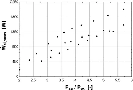
In total, 39 steady-state performance points were achieved, by varying the operating conditions of the cycle, i.e. the expander speed, the pump swept volume, the heat source/sink flow rate and temperature and the refrigerant charge. The variation range of each parameter is provided in Table 6.
Working condition Minimum value Maximum value First hot air source mean
temperature 53.4 °C 86.4 °C
Second hot air source mean
temperature 101.0 °C 163.2 °C
Air mass flow rate 0.071 kg/s 0.90 kg/s
Refrigerant flow rate 45 g/s 86 g/s
Condenser water volume flow rate 0.13 l/s 0.70 l/s Condenser mean water
temperature 13.2 °C 15.0 °C
Expander rotation speed 1771 rpm 2660 rpm
Cross-checking and redundancies
Experimental research is an open door to many measurement issues, such as sensor malfunction, bad calibration or operating mistakes on the user side. It is therefore very important to install as many redundancies in the measurements as possible to cross-check the results and detect problems at an early stage of the experimental campaign.
On the present test bench, redundancies include secondary fluids flow rate and temperature measurements, redundant pressure sensors (e.g. the use of two absolute and one differential pressure sensors on the expander), and the use of several temperature sensors on the same refrigerant line.
Figure 12 illustrates this with the heat balance across the evaporator: Q˙a is
the heat flow measured on the air side and
Q
˙
f is the heat flow measured on the refrigerant side. The subscript hx1 refers to the first of the three heat exchanger composing the evaporator. Likewise, hx12 refers to the two firstheat exchangers and hx123 to the whole evaporator. The points where a two-phase flow is present between two heat exchangers were excluded since the enthalpy cannot be calculated. An error lower than 4% on the heat balance is stated for all the point except one. The error is relatively low and can be explained by non-considered effects such as ambient heat losses.
The same analysis is performed on the condenser side, and a maximum error of 4.5% is obtained. When cross-checking the additional redundancies, an error lower or slightly higher than the inaccuracy of the considered sensor (Table 5) was obtained for all points.
The flow rate measurement can also be compared to the theoretical flow rate of the pump, given by: