1 INSTRUCTION
In order to connect the beam end-plates to the rec-tangular hollow section columns (with or without concrete inside), the following solutions are usually adopted in the construction (Figure 1): use of special bolts (blind bolts/flowdrill connectors) or use of in-termediate elements (such as reverse U channels). These solutions are adopted to overcome the diffi-culty of placing bolts when the column section is a closed one. In the blind-bolt/flowdrill bolt joints, the beam end-plates are directly connected to the col-umn faces as these bolts do not need an access to the inner side of the column faces. With respect to the joints using the U channels, a U channel is weld-ed to the column and then the beam end-plates are attached to the U channel face by ”classical” bolts. Design rules for these joint configurations are not yet covered in the current Eurocode 3, part 1-8 but these kinds of joint have been widely investigated in the literature (de Silva (2003, 2008), Elghazouli (2009), France (1999a, 1999b, 1999c), Gome (1990), Huang (2013), Jaspart (1997, 2005), Mágala-Chuquitaype (2010, 2010b, 2012), Park (2012), Vandegans (1995)). However, it can be pointed out that the two above joint solutions have some disadvantages, in particular their cost and their generally low rigidity and resistance. Indeed, on one hand, the use of spe-cial bolts or of additional pieces of the reverse U channel is costly. On the other hand, the mechanical behaviour of the mentioned joint solutions are
main-ly governed by the column or U channel faces com-ponent, subjected to the transverse tension forces through the bolts, which presents generally a rather weak rigidity and a resistance.
column end-plate beam special bolts end-plate column beam normal bolts U channel
Blind-bolt joint Reverse U channel joint
Figure 1. Blind-bolt and reverse U channel joints
concrete-filled column end-plate
beam
long bolts
Figure 2. Proposed joint configuration
Beam to concrete-filled rectangular hollow section column joints using
long bolts
V.L. Hoang, J.F. Demonceau, & J.P. Jaspart
University of Liege, BelgiumABSTRACT: This paper presents a research on a specific type of unstiffened extended end-plate joint used to connect I-shaped beams to concrete-filled rectangular hollow section columns. The main idea is to use long bolts throughout the column to connect the beam end-plates, so avoiding intermediate connecting elements (e.g. a reverse U channel) or special bolts (e.g. blind bolts). However, the use of long bolts for beam-to-column connections is still rare in the construction and no design procedure exists in the Eurocodes; this justi-fies the present research. Firstly, a test program within a RFCS European project titled HSS-SERF “High Strength Steel in Seismic Resistant Building Frames”, 2009-2013 was performed. In this project, specimens subjected to significant bending moments (and shear) or to shear only was defined. Then, analytical develop-ments based on the component approach and aimed at predicting the joint response have been carried out; their validity is demonstrated through comparisons with the tests. Finally, design guidelines have been provid-ed.
To avoid the disadvantages of the above solutions, it is proposed to use long bolts throughout the column, connecting the beam end-plates (Figure 2). Regard-ing the configuration, it appears that the cost of this joint may be reduced in comparison with the joints using special bolts or U channels. Moreover, the column face is not directly subjected to the tension forces through the bolts, so the rigidity and re-sistance of the joints may be improved. However, the use of long bolts for beam-to-column connec-tions is still rare in the construction and no design procedure exists in the current Eurocodes.
The present paper summarizes the researches on the proposed joint configuration, from the experimental tests to the development of the design procedure. Section 2 presents the application of the component method to the joint configuration; in which the addi-tional rules needing to complete the design proce-dure are highlighted. Section 3 summarizes the ex-perimental results. Section 4 devotes to the analytical developments and their validation. Section 5 is finally addressed to the concluding remarks.
2 DESIGN RULES
Let us consider a bolted extended end-plate joint us-ing “normal” bolts and H-shaped column as a refer-ence case, for which design rules are recommended in EN1993-1-8 and EN1994-1-1, and they are not reminded herein. These design rules may be applied to the investigated joint configuration; however the following remarks should be taken into account.
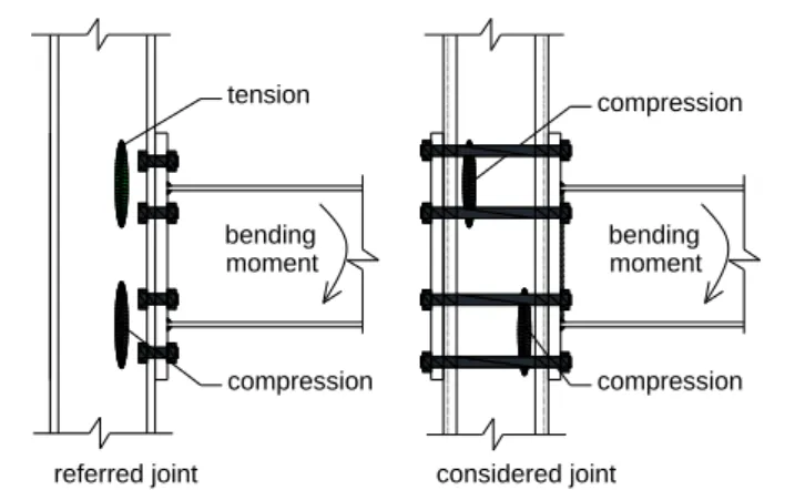
Joint under bending: Table 1 identifies the
compo-nents of the investigated joint and the corresponding design rules. In principle, the resistance and stiffness of the joint under bending can be completely charac-terized. However, the component “column webs in tension” in the reference joint (i.e. using short bolts) should be replaced by the component “column webs in compression” in the considered joint configura-tion as illustrated in Figure 3. Moreover, as the long bolts are used, the consideration of the preloading ef-fect may be included in the calculation of the joint rigidity; this aspect will be detailed in Section 4.
Joint under shear and load introduction: Table 2
identifies the activated components of the joint un-der shear loads, while Table 3 summarizes the intro-duction of shear load at the joint level. Again, the bolt preloading may influence the characterization of the joint in shear. In one hand, when the preloading is taken into account, meaning that the shear load is transferred through friction between the end-plate and the steel tube faces, design rules are available in EN1993-1-8. On the other hand, if the bolt preload-ing is omitted, some additional rules are required for the considered joints, in particular: the resistance of
the long bolts in shear, the bearing resistance of the concrete core, and the steel tube-concrete slip re-sistance. These specific components will be investi-gated in Section 4.
Table 1. Design rules for the joint under bending
N0 Components Design rules
1 Bolts in tension (1)
2 Beam web in tension
3 End plate in bending
4 Beam flange and web in compression
5 Column in compression (joint side) (2)
6 Column in compression (opposite side) 7 Column panel in shear
(1): They are basic components covered in EN1993-1-8 (§6.1.3); the design rules can be directly applied.
(2): The rules of “H-shaped column web” component in EN1993-1-8 (§6.1.3) can be used for the lateral faces of the steel tube; the rules in EN1994-1-1 may be used for the con-crete core: §A.2.3.2 for the “column panel in shear” and §8.4.4.2 for the “column in compression”.
bending moment bending moment compression compression compression
referred joint considered joint tension
Figure 3. Column components
Table 2. Design rules for the joint in shear
If the preloading in the bolts, leading to friction forces be-tween the end-plate and the column, is omitted:
No Components Design rules
End-plate in bearing Basic components in
EN1993-1-8; the rules can be directly applied. 2 End-plate in block tearing
3 Steel tube wall in bearing
4 Bolts in shear Additional rules are
needed, see Section 4. 5 Concrete core in bearing
If the preloading in the bolts is considered (slip re-sistance): see EN1993-1.8 (§3.9.1).
Table 3: Load introduction
Load transferred from the bolt to the steel tube:
min ; s
bolt tube tube bolt
s c c A E F nF nF A E A E
Load transferred from the bolt to the concrete core:
min ; c c
bolt concrete concrete bolt
s c c A E F nF nF A E A E
Slip resistance between the steel tube and the concrete:
tube concrete friction bolt
F F nF
a is the width of the tube
d is the nominal diameter of the bolt fyb is the yield strength of the bolt fub is the ultimate strength of the bolt fy is the yield strength of the tube fu is the ultimate strength of the tube
fck is the characteristic strength of the concrete fcd is the design strength of the concrete n is the number of bolt sections in shear t is the thickness of the tube wall Ac is the area of the concrete core
A is the area of the steel tube cross-section E is the Young modulus of the steel tube Ec is the Young modulus of the concrete Ftube is the bearing resistance of the tube wall (*) Fbolt is the shear resistance of the bolts(*)
Fconcrete is the bearing resistance of the concrete core(*) Ftube-concrete is the slip resistance between the steel tube and
the concrete core(*)
Lact is the active length of the bolts(*)
(*): these quantities will be clarified in Section 4.
Figure 4. Behavior of long bolts and concrete-filled column un-der shear
3 EXPERIMENTAL RESULTS
Four tests on joint under bending (and shear) and six tests on joint under shear were defined and per-formed within HSS-SERF project “High Strength Steel in Seismic Resistant Building Frames”, 2009-2013. The detail of the tests can be found in Hoang (2013), only the main points are summarized in the following.
3.1 Joint under bending
The aim of these tests was to prequalify the studied joints for building frames in medium to strong earth-quake area. Therefore, the dog-bone beam solution was used to ensure the location of the plastic hinges in the beam and so to avoid the joint yielding. Also two different steel grades (S460 and S700) were used for the column steel tubes to investigate the
possibility of using high strength steel. However, on-ly the rigidity of the joints will be presented and dis-cussed in this section.
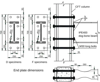
The geometrical properties and the used materials of the specimens are presented in Table 4 and Figure 5, while the test set-up is presented in Figure 6. The bolts were preloaded according to the combined method recommended in EN1090-1. The load – dis-placement (at the load application point) curves are presented in Figure 7, and one of the tested joints at failure is shown in Figure 8. The joint stiffness pro-vided by the tests are reported in Table 5. From the tests, the following observations can be done:
From the load-displacement curves, it can be seen that the rigidity of the specimens does not change during the tests, until the plastic hinges develop in the beam. It means that the bolt pre-loading remains until the end of the tests.
The joints have a quite high rigidity, the coeffi-cient kb (ratio between the joint rigidity and the unit rigidity of the IPE400 beam) are about 23.0 and 18.0 (Table 5) for D and F configurations, re-spectively, with a beam span equals to 7.5 m (span coming from the reference building from which the joints were extracted). This means that the studied joints can be classified as rigid according to the criteria recommended in EN1993-1-8 (kb ≥ 8.0 for braced frames and kb ≥ 25.0 for unbraced frames), at least for braced frames.
Table 4. Geometrical properties and used materials of the tested specimens (Figure 5)
Tests Column tube Loading protocol
D1 SHS 300x300x12.5 S460 grade Monotonic D2 Cyclic F1 SHS 250x250x10 S700 grade Monotonic F2 Cyclic
- C30/37 concrete is used for all the specimens; S355 steel is used for the beams and the end-plates; 10.9 bolts are used. - Filet welds of 5 mm and 8 mm are used to connect the beam web and beam flanges to the end-plate, respectively.
dog-bone beam IPE400 CFT column 90 260 36 15 0 40 0 15 0 70 0 50 17 7 24 6 17 7 50 250 Ø3 3 15 0 40 0 15 0 70 0 50 17 7 24 6 17 7 50 250 Ø3 3 140 120 D specimens F specimens M30 long bolts
End plate dimensions
35
Figure 6. Test set-up used for the joint specimens 0 100 200 0 100 200 D1test
Figure 7. Load-displacement curves of the joint specimens
Figure 8. D2 specimen at failure
Table 5. Stiffness of the specimens (in kNm/rad)
Test Measured stiffness Average stiffness kb factor(*)
D1 154 900 149 860 (D specimens) 23.0 D2 144 820 F1 113 850 113 400 (F specimens) 18.0 F2 112 950
(*) ratio between the joint rigidity and the unit rigidity of the
IPE400 beam.
3.2 Joints under shear
The specimen geometrical properties and materials are presented in Figure 9, more detail can be found
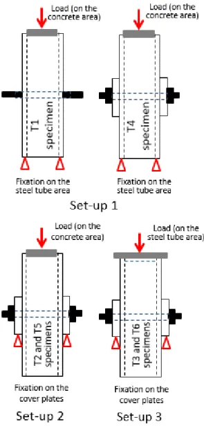
in Hoang (2013). The specimens are made of con-crete-filled rectangular column stub with a height of 1000 mm, two long bolts with a diameter of 24 mm passing through the column stub, and two cover plates representing the beam end-plates. 33 mm holes in the tube wall were made for the 24 mm bolts, and the plastic rings were used to center the bolt shanks in the holes and so, to avoid initial con-tacts between the bolts and the steel tubes. Different testing set-ups shown in Figure 10 were adopted for varied objectives, as presented in Table 6. Displace-ment transducers are used to record the displace-ments of the specimens, in particular: (1) the relative displacement between the steel tube and the bolts; (2) the relative displacement between the concrete and the steel tube; and (3) the relative displacement between the cover plates and the steel tube.
Table 7 and Figure 11 reports the reached maximal loads and the observed failure modes of all the tested specimens. Applied load vs. displacement curves are given in Figure 12. These results will be used to pro-pose analytical models in the next section.
Table 6. Objectives through the used test set-ups
Set-up Specimen Objective
Set-up 1 (Figure 10)
T1: without nuts Slip resistance between the concrete core and the steel tube with the presence of the long bolts. T4: preloaded bolts Set-up 2 (Figure 10) T2: non-preloaded bolts
Shear resistance of the bolts and bearing resistance of the concrete core. T5: preloaded bolts Set-up 3 (Figure 10) T3: non-preloaded bolts
Shear resistance of the bolts and bearing resistance of the steel tube wall.
T6: preloaded bolts
Figure 10. Used testing set-ups for the column stub tests
Table 7. Maximal loads and failure modes of the column stub tests
Test Maximal
load (kN)
Failure modes (Figure 11)
T1 1437 Significant slip between the concrete
and the tube; the bolts are significantly deformed but not failed.
T2 1218 Small slip between the concrete and the
tube; the bolt failed in shear; very small deformation of the tube in bearing.
T3 1210 Small slip between the concrete and the
tube; the bolt failed in shear; significant deformation of the tube in bearing.
T4 3516 Significant slip between the concrete
and the tube; the bolts are significantly deformed but not failed.
T5 1182 Small slip between the concrete and the
tube; the bolt failed in shear; very small deformation of the tube in bearing.
T6 1218 Small slip between the concrete and the
tube; the bolt failed in shear; significant deformation of the tube in bearing. Note that the failure sections of the bolts are at the interface between the cover plate and the steel tube, in the unthread-ed portion of the shank.
Figure 11. Critical zones in the tested specimens
a) d)
b) e)
c)
Remarks:
a: pre-loaded and non-pre-loaded bolts (set-up 1) comparison
b: set-up 2 and set-up 3 (non-pre-loaded bolts) comparison
c: pre-loaded and non-preloaded bolts (set-up 2) comparison
d: pre-loaded and non-preloaded bolts (set-up 3) comparison
e: set-up 2 and set-up 3 (pre-loaded bolts) compar-ison
4 ANALYTICAL MODELS
As mentioned in Tables 1, 2 and 3, there are some components of which the design rules should be in-vestigated, they are dealt with in this section.
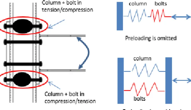
4.1 Bolt preloading effect to the joint stiffness The bolt preloading has effects on the bolt stiffness itself but also on the stiffness of the column in trans-verse compression/tension component (Figure 13). Indeed, if the bolt preloading is omitted, the bolts and the column are two separate components while they work together if the preloading is considered as represented in Figure 13. The following equations can be used to estimate the effective stiffness of the “column + bolt” component for the two cases:
1
(1/
1/
)
column bolt column bolt
k
k
k
(1)column bolt column bolt
k
k
k
(2)where the preloading effect is omitted and consid-ered, respectively.
In Eqs. (1) and (2), kcolumn and kbolt are respectively
the stiffness coefficients of the “column in compres-sion/tension” component and “bolt in tension” com-ponent when they are considered in isolation, using the formulas recommended in EN1993-1-8 and EN1994-1-1.
Normally, the rigidity of the concrete-filled column in compression is much higher than the one of the long bolts in tension. Therefore, it can be seen that the joint stiffness is considerably increased if the preload in the bolts is taken into account (k given by Eq.(2) is much higher than k given by Eq.(1)).
Figure 13. Effect of the bolt preloading on the joint stiffness
The rigidity of the components of the tested speci-mens were calculated, the detail can be found in Comeliau (2012) and Hoang (2014), the results are summarized in Table 8. A very good agreement is observed between the test results and the proposed model predictions taking into account the bolt pre-loading, with a difference of less than 3%. Moreo-ver, a significant difference between the stiffness with and without account of the preloading is ob-served with a ratio between these two stiffness of 1.8
for specimens D and of 1.5 for specimens F, the stiffness with account of the preloading being the highest ones.
Table 8. Joint stiffness comparison (in kNm/rad)
Specimens Eq.(1) Eq.(2) Tests (Table 5)
D 82986 149720 149 860
F 77383 115970 113 400
4.2 Joint under shear and load introduction
As mentioned in Tables 2 and 3, the following quan-tities should be considered:
The shear resistance of the long bolts (Fbolt);
The bearing resistance of the concrete core (Fconcrete);
The friction resistance between the tube and the concrete core (Ftube-concrete).
4.2.1 Shear resistance of the bolts
The behavior of the bolts subjected to shear or to shear + bending is studied using the results from testing setups 2 and 3 (Figure 10), i.e. through tests T2, T3, T5 and T6. The maximal loads (around 1200 kN) and the failure modes (bolts in shear) are almost the same for these tests (Table 7 and Figure 11) which indicates that:
At the ultimate state, there is no significant ef-fect of the bolt preloading on the bolt shear re-sistance;
The bending moment due to the gap between the application of the shear through the concrete core and the bolt support (equal to the tube thick-ness, see the testing setup 2 in Figure 10) is not significant and so, does not affect significantly the shear resistance of the bolts.
From the above observations, it seems to be reason-able to propose to use the shear resistance of bolts as given in EN1993-1-8 (§3.6.1) to predict the shear re-sistance of the long bolts in the investigated joints:
2 v ub bolt bolt M f A F (3) the coefficient v is provided in EN1993-1-8, M2 is the safety factor, fub is the ultimate strength of the bolt, Abolt is the area of the bolt cross-section in shear.
If formula (3) is used for the tested specimens:
Fbolt=40.6fubAbolt = 1172 kN, where fu,b= 1008
N/mm2 (from the coupon tests); Abolt = 452 mm2
(nominal value); M2 is taken as 1.0 (to compare with the test result); and “4” is the number of bolt cross-section in shear. In comparison with the test value (Table 7), it can be seen that the use of the EN1993-1-8 formula to estimate the bolt strength in shear al-lows obtaining a good agreement with the test re-sults.
4.2.2 Bearing resistance of the concrete core The bearing resistance of the concrete core de-pends on two parameters: (1) the “active” length of the bolts taking into account their flexibility, and (2) the concrete strength taking into account the con-finement effect.
Active length of the bolts
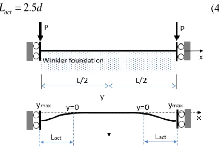
The model of a beam on an elastic foundation is used to estimate the active length of the long bolts; the Winkler foundation is adopted (Figure 14). The rotation of the two beam ends are supposed to be ful-ly restrained due to the effects of the bolt nut and head. Two concentrated loads are considered at the two ends to simulate the action coming from the end-plates. The thickness of the steel tube wall is neglected in the model. It is proposed to define the active length as the distance from the beam end (the displacement is maximum) to the point where the displacement is considered as vanished (Lact in Fig-ure 14). The following value is obtained for the ac-tive length of the bolt:
2.5
act
L d (4)
Figure 14. Active length of the bolts Strength of the concrete core
Two effect should be taken into account when com-puting the strength of the concrete core under the bolts: the confinement effect due to the steel tube, and the local effect of the load. In this work, the strength of the concrete in the filled square hollow section, partially loaded, given in EN1994-1-1, §6.7.4.2(6) is proposed to be applied, in details:
, 1 1 (1 y ) c, c cd , c Rd cd cL y ck f A A f t f f a f A A
(5)where A1 is the loaded area under the active length of the bolts, equals to Lact.d; ηcL is a coefficient tak-ing into account of the shape of the steel tube, equals to 3.5 for square sections; the other notation are de-fined in Figure 4.
Bearing of the concrete core
From the active length of the bolts (Eq.(4)) and the strength of the concrete (Eq.(5)), the bearing
re-sistance of the concrete core for one shear plane can be defined:
2
2.5
concrete act Rd Rd
F L d
d
(6) In Eq.(6), d is the nominal diameter of the unthread-ed portion of the bolts.Eq.(6) is applied to compute the resistance of the concrete core of the tested specimens, 2380.1 kN for each specimen is obtained (fck=45 N/mm2 from the coupon tests, fy=900 N/mm2 is used as the nominal value for the bolt). It shows that the resistance in bearing of the concrete core is higher than the bolt resistance in shear, it is in agreement with the test observations (T2 and T5 tests). However, the bearing resistance of the concrete core was not exposed through the tests and so, the so-obtained values can-not be strictly validated.
4.2.3 Steel tube – concrete slip resistance
Discussion on the test results
Tests T1 and T4 were dedicated to the characteriza-tion of the slip resistance between the steel tube and the concrete core. As can be seen in the test results reported in Table 8 and Figure 12, significant loads were reached during these tests, in particular for T4 test (3516 kN, in comparison to 1200 kN for the oth-er tests).
During Test T4, a slip between the steel tube and the concrete occurred at a load of around 1500 kN. Then, the bolts entered into contact with the steel tubes and shear forces developed in these bolts; the system was able to sustain an additional load of around 2000 kN. However, as highlighted above, the shear resistance of the bolts has been estimated ex-perimentally as equal to 1200 kN, which means that the bolt in shear was not the only component to sup-port the additional load of 2000 kN.
This “over” resistance has been associated to the de-velopment of confinement effects in the concrete core, leading to high frictions between the steel tube and the concrete. The confinement effect becomes very important when the stress in the concrete is high leading to the change of Young modulus and Poisson ratio of the concrete. Noting that at the end of test T4, the normal stress in the concrete core equals to 66 N/mm2 while the cylinder strength equals to 45 N/mm2. A model to estimate the force in the bolts taking into account the friction has been established in Hoang (2013). It shows that even the external load of 3500 kN but the shear load in the bolts is less than 1200 kN – the ultimate value of the bolt in shear, in agreement with the test results.
Proposed model
Even a very high friction between the tube and the concrete is observed through the tests, and this phe-nomenon is well modelled, it is not reasonable to consider this effect in practice. Indeed, the stress in
the concrete in the test is much higher than the nom-inal strength but this situation does not necessarily occur in practice. Therefore, the recommendation given in EN1994-1-1 (§6.7.4.2) on the friction be-tween the concrete core and the steel tube is pro-posed to be applied for the investigated case, in which the confinement effect due to the present of the bolts are taken into account:
( 2 ) / 2
tube concrete Rd bolt bolt
F a t b F nF (7) where a and t are defined in Figure 4;
Rd is theshear strength, which may be taken as equal to 0.4 N/mm2 (see EN1994-1-1); μ is the friction coeffi-cient, which may be taken as 0.5 (see EN1994-1-1),
Fbolt is the shear resistance of the bolt (Eq.(3)), n is the number of bolt sections in shear.
5 CONCLUSION
A research conducted on bolted extended end-plate beam to concrete-filled rectangular hollow section column joint using long bolts was presented in this paper. It shows that the use of long bolts is a good solution to connect the beam end-plate to the con-crete-filled rectangular hollow section column. It can avoid the use the intermediate elements (such as reverse U channels) or the use of special bolts (blind bolts/flowdrill connectors), leading to a saving of cost. The conducted experimental tests demonstrated the good mechanical behavior of the joints, in par-ticular a high rigidity under bending and a high re-sistance in shear. Based on the component methods, some additional rules were proposed to complete the already available design rules for the investigated joints under bending, under shear and load introduc-tion at the joint. The proposed models were validat-ed through comparisons to the experimental results.
ACKNOWLEDGEMENTS
This work was carried out with a financial grant from the Research Fund for Coal and Steel of the European Community, within HSS-SERF project “High Strength Steel in Seismic Resistant Building Frames”, Grant N0 RFSR-CT-2009-00024.
REFERENCES
Comeliau L., Demonceau J.F., Jaspart J.P. 2012. Computation note on the design on bolted beam-to-column joints within HSS-SERF project. Internal report, University of Liege. de Silva L.S., Neves L.F.N., Gomes F.C.T. 2003. Rotational
stiffness of rectangular hollow section composite joints.
Journal of Structures Engineering 129 (4).
de Silva L.S. 2008. Towards a consistent design approach for steel joints under generalized loading. Journal of
Construc-tional Steel Research 64: 1059-1075.
Elghazouli A.Y. Mágala-Chuquitaype C., Castro J.M., Orton A.H. 2009. Experimental monotonic and cyclic behaviour
of blind-bolted angle connections. Engineering Structures
31: 2540-2553.
EN1090-2. 2008. Execution of steel structures and aluminium structures - Part 2: Technical requirements for steel struc-tures. CEN, Brussels.
EN1993-1-8. 2005. Design of steel structures. Part 1.8: Design of joints. CEN, Brussels.
EN1994-1-1. 2005. Design of composite steel and concrete structures. Part 1.1: General rules and rules for buildings.
CEN, Brussels.
France J.E., Davison J.B., Kirby P.A. 1999a. Strength and rota-tion response of moment connecrota-tions to tubular columns us-ing flowdrill connectors. Journal of Constructional Steel
Research 50: 1-14.
France J.E., Davison J.B., Kirby P.A..1999b. Strength and rota-tion response of simple connecrota-tions to tubular columns us-ing flowdrill connectors. Journal of Constructional Steel
Research 50: 15-34.
France J.E., Davison J.B., Kirby P.A.. 1999c. Moment-capacity and rotational stiffness of endplate connections to concrete-filled tubular columns with flowdrilled connectors. Journal
of Constructional Steel Research 50: 35-48.
Gome FCT. 1990. Etat limite ultime de la résistance de l’ame d’une colonne dans un assemblage semi-rigide d’axe faible (in french). Technical Report 203, University of Liege. Hoang V.L., Demonceau J.F., Jaspart J.P. 2014. Innovative
bolted beam-to-column joints in moment resistant building frames: from experimental tests to design guidelines. In “Application of High Strength Steel in Seismic Resistant Structures”, Ed. by Dubina et al. “Orizonturi Universitare”
Publishing House, Romania.
Huang S.S., Davison B., Burgess I.W. 2013. Experiments on reverse-channel connection at elevated temperatures.
Engi-neering Structures 49: 937-982.
Jaspart J.P. Pietrapertosa C., Weynand K., Busse E., Klinkhammer R. 2005. Development of a full consistent de-sign approach for bolted and welded joints in building frames and trusses between steel members made of hollow and/or open sections: application of the component method.
CIDECT Report 5BP – 4/05, Vol 1: practical guidelines.
Jaspart J.P. 1997. Recent advances in the field of steel joints – Column bases and further configurations for beam-to-column joints and beam splices. Agregation Thesis,
Univer-sity of Liege.
Hoang V.L. et al. 2013. High Strength Steel in Seismic Re-sistant Building Frames. HSS-SERF project, Deliverable D4: Prequalification tests on bolted beam-to-column joints in moment-resisting dual-steel frames. University of Liege. Mágala-Chuquitaype C., Elghazouli A.Y. 2010. Behaviour of
combined channel/angle connections to tubular columns under monotonic and cyclic loadings. Engineering
Struc-tures 32: 1600-1616.
Mágala-Chuquitaype C., Elghazouli A.Y. 2010b. Component-based mechanical models for blind-bolted angle connec-tions. Engineering Structures 32: 3048-3067.
Mágala-Chuquitaype C., Elghazouli A.Y. 2012. Response and component characterization of semi-rigid connections to tubular column under axial loads. Engineering Structures
41: 510-532.
Park A.Y., Wang Y. C. 2012. Development of component stiff-ness equation for bolted connection to RHS columns.
Jour-nal of ConstructioJour-nal Steel Research 70: 137-152.
Vandegans D., Janss J. 1995. Connection between steel beam and concrete-filled R.H.S. based on the stub technique (threaded stub). In “Connections in steel structures III: Be-haviour, strength and design”, Ed. by Bjorhovde R., Colson A., Zandonini R.