© Mahdi Askaripour, 2018
Improving the reactivity of ilmenite as an oxygen carrier
in chemical looping combustion
Mémoire
Mahdi Askaripour
Maîtrise en génie des matériaux et de la métallurgie - avec mémoire
Maître ès sciences (M. Sc.)
II
Improving the reactivity of ilmenite as an
oxygen carrier in chemical looping combustion
Mémoire
Mahdi Askaripour
Sous la direction de :
Houshang Alamdari, directeur de recherche
Serge Kaliaguine, codirecteur de recherche
III
Résumé
La combustion en boucle chimique (CLC) est l'une des technologies appropriées pour produire l'énergie permettant la capture facile de CO2. Dans ce système, le transporteur d'oxygène réagit avec l'agent combustible dans le réacteur de combustion, puis il se dirige vers le réacteur d'oxydation et réagit avec l'oxygène pour retrouver sa première forme. Après la réaction de réduction, le CO2 peut se stocker facilement, puisqu’il est pur et exempte d’azote. Le transporteur d'oxygène en CLC joue un rôle important. Selon la littérature, l’ilménite est l’un des matériaux pouvant jouer le rôle du transporteur, mais il a montré une faible réactivité pour la combustion du CH4. Dans ce projet, nous avons examiné la possibilité d'augmentation la réactivité de l’ilménite par augmentation de sa surface spécifique et l'ajout de NiO. Au total, quatre échantillons ont été préparés par la méthode de broyage, en utilisant un broyeur à billes à basse et à haute énergie. La réactivité de l'ilménite avec CH4 a été déterminée. Les techniques de BET, l’analyse thermogravimétrique (TGA) et la diffraction des Rayons X (XRD) ont été utilisées pour la caractérisation des échantillons. Les résultats ont montré que la grande surface de l'ilménite avec 8 % de NiO mène à une réactivité et une capacité de transfert d'oxygène élevée lorsque le CH4 est utilisé comme combustible.
IV
Abstract
Chemical looping combustion (CLC) is one the suitable technologies to produce the energy allowing easy capture of CO2. In this system, an oxygen carrier reacts with a fuel agent in the fuel reactor and then it goes toward the oxidation reactor and reacts with oxygen to return to the initial form. After reduction reaction, CO2 can be stored easily since it is almost pure and free from nitrogen. So, the oxygen carrier in CLC plays an important role. Based on the literature, ilmenite has shown low reactivity when CH4 was used as fuel. In this project, increasing the surface area of ilmenite and addition of NiO were explored aiming at increasing the reactivity of ilmenite with CH4. Samples were prepared by mechanical milling , using low and high energy ball milling steps. Different techniques such as BET, thermo gravimetric analysis (TGA) and X-ray diffraction (XRD) were used to characterize the oxygen carrier and its reactivity with CH4. The results showed that the high surface area of ilmenite containing 8 % NiO exhibited high reactivity and high oxygen transfer capacity when CH4 was used as fuel.
V
Table of Contents
Résumé ... III Abstract ... IV List of figures ... VI List of tables ... VIII Dedication ... IX Acknowledgement ... X
Chapter 1: Introduction ... 1
1.1 Greenhouse gasses and carbon capture technology ... 1
1.2 Chemical looping combustion process (CLC) ... 2
1.3 Oxygen carrier ... 3
1.4 Comparison of ilmenite with different materials as Oxygen Carrier in CLC ... 7
1.5 Reactivity of ilmenite with respect to different fuels ... 15
1.6 Issues encountered with oxygen carriers ... 33
1.7 Cost of oxygen carrier ... 34
1.8 Hypothesis and objectives of thesis ... 34
Chapter 2: Methodology ... 36
2.1 High Energy Ball milling ... 36
2.2 Low Energy Ball Milling (Attrition Mill) ... 37
2.3 BET analysis ... 37
2.4 X-ray diffraction ... 37
2.5 Thermo gravimetric analysis (TGA) ... 38
2.6 Data Evaluation ... 39
Chapter 3: Results and discussion ... 40
3.1 Physical characterization ... 40
3.1.1 X-Ray diffraction measurement of samples ... 40
3.1.2 Surface area measurement of pure ilmenite after HEBM ... 44
3.2 Thermo gravimetric analysis (TGA) ... 47
Conclusions ... 52
Future works ... 54
VI
List of Figures
Fig. 1: Principle of chemical looping combustion ... 2 Fig. 2: Oxygen transfer capacity of different oxygen carrie ... 4 Fig. 3. a) Rate of char gasification in the reduction periods as a function of char conversion of two manganese ores, b) Effect of temperature on the rate of char gasificat ... 8 Fig .4. a) Reduction reaction of 15g ilmenite with CH4 at temperature 950 ◦C, b) Reducing 14.25 g ilmenite and 0.75 g NiO-based material with CH4 at 950 ◦C ... 8 Fig. 5. a) Reduction and b) oxidation of different ilmenite granular, G1: 85 % IL +15 % TiO2, G6: 85 % IL + 15 TiO2, G10: 85 % IL + 15 % Mn2O3, G11: 75 % IL + 25 % Mn2 ... 9 Fig. 6. a) Conversion of H2 with MIOX ME 400 and ilmenite at 900 C, b) Conversions of CH4 with MIOX ME 400 and ilmenite at 900 C, c) Conversion of CO with MIOX ME 400 and at 900 ... 11 Fig. 7. Carbon capture efficiency, oxygen demand and gas concentration of ilmenite and manganese with pet coke as fuel ... 12 Fig. 8. Comparison of bed feed using ilmenite and bituminous coal as fuel ... 13 Fig. 9. Packed bed reactor ... 14 Fig. 10. Total conversion of CO (γCOtot) during an entire reduction as a function of cycle number for a) the oxide scales and b) the other materials and the reference sample, ilmenite 14 Fig 11. Reactivity of ilmenite with CH4 as reducing gas, b) reactivity of ilmenite with syngas as reducing gas ... 15 Fig. 12. a) gasification and b) combustion efficiency variation of ilmenite with the temperature of reducer, c) CO, CO2 and H2 concentration in the reducer at different reducer temperature for different coal particle size ... 16 Fig. 13. SEM images of a) details of the external surface, b) details of the cross section inside the particles and c) cross section of a particle for pre-oxidized ilmenite, after 3 cycles and after 13 cycles using coal char as fuel ... 18 Fig. 14. Concentration profile of the 49th cycle of ilmenite (last cycle) with Chinese bituminous mixed with 33.3 wt.% of coal gasification ash ... 19 Fig. 15. a) Char conversion, b) carbon capture and c) combustion efficiency variation with fuel-reactor temperature for various coal particle sizes. Particle size: () 74–125 m; c) () 125– 200 m; (□) 200–300 m. (d, e, f) CO2, CO and H2 concentration in the fuel-reactor (dry free N2 basis) at different fuel-reactor temperatures for different coal particle size. Particle size: () 74–125 m; () 125–200 m; (󠇅□) 200–300 m. (g) Oxygen demand variation with the fuel-reactor temperature for different coal particle sizes ... 21 Fig. 16. a) Hydrogen conversion γH2 against degree of mass-based conversion for different temperatures b) Carbon monoxide conversion against degree of mass-based conversion for different temperatures ... 22 Fig. 17. Elemental maps of Fe (red), Ti (yellow) and O (pink) on three representative particles varying in porosity and morphology. Measured porosity is increasing in the particles from left to right………...22 Fig. 18. Comparison of experiments two fuels, free-sulfur and sulfurous kerosene ... 23 Fig. 19. a) Velocity vectors (m/s) and volume fractions of iron oxide and coal particles at 175 s, temperature of 1273 K and 50 % steam concentration. a1) Iron oxide and a2) Coal. b) Instantaneous gas species mass fractions at 175 s, temperature of 1273 K and 50 % steam concentration. b1) H2O, b2) CO2 and b3) H2. Gasification rate of char (kmol / (m3 s) of char). c) Steam gasification rate and (d) CO2 gasification rate... 24 Fig. 20.a) Complete reduction of ilmenite b) TGA test of 10 redox cycles, particle size 150-250μm,T=9501050C………..……….25 Fig. 21. Surface morphology of ilmenite ore; a) raw ilmenite and b) calcined ilmenite ... 26 Fig. 22. a) Integral CO2-yields during reduction with syngas (H2/CO-50/50), b) CO2 yield during reduction with syngas (H2/CO-50/50) for the last cycle as a function of oxygen carrier conversion (ω) ... 27
VII
Fig. 23. The mole fraction (dry gases) for the last reduction period (a) synthetic ilmenite (50 % Fe and 50 % Ti) and, b) natural Norwegian ilmenite, c) Conversion of CO as a function of the mass-based conversion of the oxygen carriers (󠇅ω) for three of the synthetically produced materials and the two natural ilmenites at the last cycle (stable condition) ... 28 Fig. 24. Thermograms obtained during the reduction of activated ilmenite using different H2O/H2 ratios at 1173 K ... 29 Fig. 25. a) Variation of the oxygen transport capacity, normalized reactivity, rate index with the number of redox cycles solid conversion variation, c) Mass variations d) Normalized conversion during the oxidation reaction ... 30 Fig. 26. Profiles of CO2 or H2O fractions in the product gas (wet basis) during consecutive reduction periods, for a) CH4, b) CO and c) H2 as reducing gases (D). Oxygen yield ... 31 Fig. 27. Fuel conversion a) and CO2 yield b) for 100 % natural gas operation with different solids inventories. Ratio CO/CO2 (c) and ratio H2/CO d) in fuel reactor exhaust gas for natural gas operation with different solids inventories ... 32 Fig. 28. a) Concentration profile during the reduction of 40 g Fe2O3/MgAl2O4 with 0.2 g petroleum coke. The inlet concentration of H2O is 50 %. The temperature is 950 C. b) Concentration profile during the reduction of 40 g ilmenite with 0.2 g petroleum coke. The concentration of H2O is 50 %. The temperature is 950 C ... 33 Figure 29: X-ray diffraction patterns of ilmenite samples. Samples were ball milled from 0 min to 180 min. The reference peaks of Ilmenite and Magnetite are presented at the bottom of the graph. ... 42 Figure 30. Variation of crystallite size as a function of high-energy ball milling time. ... 42 Figure 31: X-ray diffraction of ilmenite with 4 and 8 wt.% of NiO. Ilmenite was first milled for 3 h, then NiO was added and the mixture was further milled for 2 h. ... 44 Figure 32: Surface area measurement of pure ilmenite ... 45 Figure 33: Oxygen exchange cycles of un-milled ilmenite at 900 °C (oxidation was performed under 50 vol.% air; reduction was performed under 15 vol.% CH4). ... 47 Figure 34: Oxygen exchange cycles of HEBM-milled ilmenite at 900 °C. The sample was milled in high energy ball mill for 180 minutes. (oxidation was performed under 50 vol.% air; reduction was performed under 15 vol.% CH4). ... 49 Figure 35: Oxygen exchange cycles of high surface ilmenite at 900 °C. The sample was milled in high energy ball mill for 180 minutes, followed by milling in low energy ball mil for 60 minutes. (oxidation was performed under 50 vol.% air; reduction was performed under 15 vol.% CH4). ... 50 Figure 36: Oxygen exchange cycles at 900 °C of doped ilmenite with 8 wt.% NiO. The sample was milled in high energy ball mill for 180 minutes, followed by milling in low energy ball mil for 60 minutes. (oxidation was performed under 50 vol.% air; reduction was performed under 15 vol.% CH4). ... 51
VIII
List of Tables
Table 1: Samples compositions ... 7
Table 2. The composition of samples (G: Granules, FR: Fluted rings, I: ilmenite, T: TiO2, M: Manganic oxide). ... 10
Table 3: Ilmenite and MIOX composition ... 10
Table 4: Reduction and oxidation form of ilmenite ... 16
Table 5. The crystallite domain size of the samples ... 42
IX
Dedication
Dedicated to my Mother, Father and my Love, Zahra, Hossein and Betisa.
X
Acknowledgement
I would like to express my thanks to my supervisor, Prof. Houshang Alamdari for his infinite support, encouragement and all his experience that he shared with me. His incessant perseverance and the trust he confided in me helped me mature from a regular graduate student to an individual capable of multi-tasking research projects. It was my great pleasure to work with him for my graduate studies and gain invaluable experience during these years. I am very grateful to my co-supervisor Prof. Serge Kaliaguine who put his efforts and expertise on this project similarly to the main supervisor. His assistance and support throughout the course of this research is greatly appreciated
I do not know how to express my sincere gratitude to my mother and father, Zahra and Hossein, to whom I owe all my success and life. They are those who persistently encourage me whenever I face disappointment. Their encouragements, support and sympathy were the essential driving force for me to deal with challenges and pursue my work. My mother never forgot to call every day to listen to me and give me hope and patience for a brilliant future.
I would like to sincerely thank my lovely wife, Betisa, for all her kind support, patience and encouragements during these years, without her support it would be so difficult to finish this step of my life.
The help of Dr. Davood Karimi, staff member of research lab of Calgary university is greatly appreciated for his valuable technical support and innovative suggestions.
I would like to specifically thank my dear friends at Laval, Mohammad, Masoud and Fatemeh, Mehdi and Rana, Kavand, Farzaan, Amin and Saba, Tohid and Mahboobeh, Hadi and Samira. Thank you for the confidence you gave me and for all the shared laughs that made some “heavy days” lighter. I wish you all best of luck in your life.
Chapter 1: Introduction
1.1
Greenhouse gasses and carbon capture technology
The global warming by greenhouse gasses has become one of the important issues in the world. The main greenhouse gases are: methane (CH4), nitrous oxide (N2O) and carbon dioxide (CO2). The CO2 is one of the important gases, which is produced by burning of fossil fuels for power generation and transportation. The use of fossil gas is unavoidable because of its lower cost and higher energy density compared to the alternative sources [1].
It has been reported that in the USA 83 % of GHG emission is generated from combustion of fossil fuels [2]. Energy Information Administration (EIA) estimated that the amount of combustion fossil fuels would increase by 27 % over the next 20 years. China is the second country after the USA, which contributes to 13.6 % of the total world CO2 emissions [3]. So, mitigation and controlling of the CO2 emission in the atmosphere is necessary. Several methods have been suggested to reduce the CO2 emissions, such as substitution to less carbon-intense fuels and using renewable energy [4].
Carbon capture and sequestration(CCS) is one of the promising ways to mitigate CO2 release in the atmosphere. The capture of CO2 needs high concentrations of CO2, which can be forwarded and sequestrated underground. Some current technologies, which have been used in industry, are post-combustion, oxy-fuel combustion and pre-combustion [5,6]. These technologies lead to increase the process cost because a large portion of the produced energy is consumed for the capture of CO2. The capture of carbon would increase the electricity cost by 50 %. [7,8]. So, these techniques are limited by high cost.
The use of renewable energies such as hydraulic power, biomass, wind and solar energy is another way to reduce the CO2 emissions in the atmosphere. The hydraulic energy is the most exploited one in comparison with the other methods. Biomass is defined as
2
any organic matter, such as wood, wood waste and residues, agricultural residues, municipal waste, animal waste and aquatic plants. In spite of the decrease in renewable energy prices and the increase in the fossil fuel prices, just 8.5 % of total energy demands are planned to come from renewable energy in 2030 [5,7,8,9]. Hence, utilizing the technologies, which both decrease the cost of capture and storage of CO2 and increase the thermal efficiency of power plants is necessary. Chemical looping combustion is a new combustion technology, which can increase the thermal efficiency of the power plants with inherent capability for separation of CO2 [1].
1.2 Chemical looping combustion process (CLC)
This process is based on the supply of oxygen to the fuel by a solid oxygen carrier, avoiding direct contact between the fuel and air. Using this process, the reaction by-product would be a mixture of pure CO2 and water vapor and the high cost related to the nitrogen separation would be avoided. The chemical looping combustion has two main reactions that occur in two separate reactors. The schematic representation of the chemical looping combustion is illustrated in Figure 1.
3
The system consists of two fluidized bed reactors. In the fuel reactor, hydrocarbon fuels, such as syngas or natural gas, react with a metal oxide carrier (MxOy) where the metal oxide is reduced to MxOy-1. The air reactor is an oxidation reactor where the reduced carrier (MxOy-1) reacts with air and is re-oxidized. Then, the re-oxidized carrier goes back to the fuel reactor to provide oxygen for the fuel reaction. In other words, the oxygen carrier simply picks the oxygen from the air reactor and brings it to the fuel reactor, thus avoiding the dilution of the reaction by-products by nitrogen.
The exhaust gasses from the air reactor are nitrogen and some unreacted oxygen, which could be vented into the atmosphere. The exhaust gasses from the fuel reactor are CO2 and water vapor. After water separation, a highly concentrated CO2 is obtained, being ready for further sequestration operations or other uses.
The reactions in two reactors are as follows where MxOy is the oxygen carrier and CnH2m is the hydrocarbon fuel:
(2n + m) MxOy + CnH2m (2n + m) MxOy-1 + mH2O + nCO2 (Reduction) (Eq. 1-1)
MxOy-1 + ½ O2 MxOy + air (N2 or unreacted O2) (Oxidation) (Eq. 1-2)
And the net reaction throughout the chemical looping system is:
CnH2n + (n+½m) O2 mH2O + nCO2 (Eq. 1-3)
The reaction 1-1 that occurs in the fuel reactor can be exothermic or endothermic, based on the type of the fuel, which is used in the rector. The reaction 1-2 is always exothermic.
1.3
Oxygen carrier
The choice of suitable oxygen carrier for chemical looping combustion is of great importance, determining the performance and efficiency of the system. A successful operation system strongly depends on the performance of the oxygen carrier. Many scientists investigated the behavior of a number of materials in CLC systems [10, 11]. Several parameters are important for choosing a suitable oxygen carrier, e.g. good oxygen carrier capacity, high reactivity in both fuel and air reactors, high mechanical
4
strength during reduction – oxidation cycles, high melting point, satisfactory long-term recyclability and durability during cycles, low activity toward coke formation, low cost and being environmentally friendly.
The maximum oxygen – carrying capacity of the carrier gives rise to a lower particle circulation rate. The property of primary metal oxide and the support, used in preparing metal oxide, determines the oxygen – carrying capacity. The values of oxygen – carrying capacity (RO) of some oxygen carriers are illustrated in Figure 2. Higher RO values belong to CaSO4, Co3O4, NiO and CuO [12].
Fig. 2: Oxygen transfer capacity of different oxygen carriers [12].
The addition of supports to the oxygen carrier would help improve the properties of the oxygen carrier such as mechanical strength, reactivity of oxygen carrier, and its oxygen transfer capacity. For instance, pure NiO-based oxygen carriers showed low reactivity in CLC process but the NiO-based oxygen carrier supported on -Al2O3, MgAl2O4, CaAl2O4 showed very high reactivity compared to NiO-based oxygen carrier prepared on -Al2O3 [12]. The use of alumina as support has shown a positive effect on the Fe-based oxygen carrier and its oxygen - transport capacity [13].
The oxygen carrier must move numerous times between the fuel and the air reactors and it must be under reduction and oxidation reactions for long time. Therefore, having high mechanical strength and stable structure of metal oxide are among the important
5
parameters for choosing the proper oxygen carrier. The particle’s chemical composition is closely related to their mechanical strength [14].
The high rate of oxygen carrier reaction results in a fact that the oxygen carrier could be used in small reactor to achieve the same reactant conversion. The rate of reaction can be higher by convenient selection of primary metal oxide, support material, and reaction conditions. For example, most of the NiO-based oxygen carriers supported on Al2O3 compounds showed very high reactivity with all fuel gases, except for -Al2O3, due to solid state reaction between NiO and -Al2O3 [15,16].
Ni-based oxygen carrier is one of the desirable materials, which has shown good performance in CLC. Nickel oxide is more expensive than most of the other metal oxides, but this problem can be solved using particles with low nickel content. NiO-based oxygen carriers have shown very high reactivity and high mechanical strength in CLC at high temperatures (900 -1100 °C). To improve their properties and reactivity compared to pure NiO particles, different support materials and different preparation methods such as spray drying [17], incipient impregnation [18], and mechanical mixing [19] have been suggested. The agglomeration of nickel oxide has an effect on its reactivity in the CLC. Therefore, using of support can improve the reactivity of nickel oxide and reduce its agglomeration in CLC process. Most of the NiO-based oxygen carriers, supported on Al2O3 compounds, showed very high reactivity with all fuel gases. This support did not show agglomeration problems, had low attrition rates, and no carbon deposition in CLC [20,21].
Cu-based oxygen carriers have shown high reaction rate and good oxygen transfer capacity. Generally, copper is cheaper than nickel and cobalt, used in CLC. All the supports were suitable to increase the reactivity of Cu-based oxygen carrier. Cu-based oxygen carrier which were prepared by impregnation on SiO2, TiO2 and Al2O3 showed excellent reactivity in the oxidation and reduction reaction, maintaining chemical stability and mechanical strength after multicycle testing [22,23,24,25], despite the fact that they showed agglomeration problem due to low melting point of Cu (1085 °C) [26,27]. To prevent agglomeration problems, the content of Cu must be lower than 20 % or a mixed oxide system of Fe2O3/CuO with MgAl2O4, as supporting material, must be used. Berguerand et al. 2011, showed that the most important parameter which can affect the performance and reactivity of Cu-based oxygen carrier is carrier-to-fuel ratio
6
(). If the oxygen carrier works on 1.4 at 800 °C, all methane, as reducing gas, is converted without CO or H2 emissions. Under these conditions of operation, no carbon formation or any other problems were detected [28].
Mn-based carrier is another type of oxygen carrier. It has been used in CLC because it has higher oxygen transfer capacity, non-toxicity and lower cost. The reactivity of pure manganese oxide as oxygen carrier was low when methane and coal were used as reducing gas [29,30]. The inert supports such as SiO2, TiO2, Al2O3 and MgAl2O4 could improve its reactivity in the CLC process [31,32,33,34,35]. Bentonite as a binder could increase reactivity of manganese, based on TGA analysis [36]. When ZrO2 is used as support, the reactivity of manganese is improved with methane [37] but it exhibited cracks in the structure due to the phase transformation during the repeated reduction and oxidation cycles. The addition of MgO, CaO and CeO2 could reduce this problem [32,37,38].
Cobalt oxide is another material that can be used as oxygen carrier in CLC. There are few studies about materials containing cobalt. CoO-based oxygen carriers were used with several supports and TGA analysis results showed that CoO/YSZ (YSZ: Yttria Stabilized Zirconia as binder) has good reactivity and low carbon deposition [39,40]. A 50 kWh CLC system operated with CoAl2O4 as oxygen carrier. The results showed that the conversion to CO2 was around 99.6 %. [41,42].
Nowadays, interest in the use the low-cost materials with high reaction rate has increased. Ilmenite is one of the promising low-cost materials for this end. Ilmenite is a natural mineral of titanium ore, which is composed of FeTiO3. Its appearance is very similar to magnetite but its structure is different. The iron phase of ilmenite behaves as an oxygen carrier in CLC. It could be a promising oxygen carrier for gaseous fuels combustion in a CLC. Ilmenite has also shown a good mechanical strength in the CLC process. It has shown some agglomeration problems. Most recent researches have shown that it has good oxygen carrying capacity and high level of attrition resistance [43,44,45,46]. Furthermore, the cost of ilmenite is significantly lower than the pure or supported metal oxides.
7
1.4
Comparison of ilmenite with different materials as Oxygen
Carrier in CLC
The reactivity of four types of manganese oxides and ilmentite were compared for char gasification and the results showed higher reactivity for manganese ores, being 1.5 times higher than that of ilmenite [43,46]. The char gasification decreased as the number of cycles increased. They showed that the increase of the temperature of reducer could increase the char gasification [44]. Figure 3 (a) shows the instantaneous rate of char gasification as a function of char conversion for the four manganese minerals at 950 ºC after successive redox cycles. The compositions of samples are indicated in Table 1. The manganese minerals were named according to their origin as MnSA from South Africa (SA); MnGBHNE and MnGBMPB from Gabon (GB) together with the abbreviated name of the supplier, i.e., Hidro Nitro Españ ola S.A. (HNE) and Mario Pilato Blatt S.A. (MPB); and finally, MnBR from Brazil (BR). Arjmand et al. 2014, showed that the presence of K and Na impurities in the manganese ore could instantaneously increase the rate of char gasification for CLC with solid fuels [48].
Table 1: Samples compositions [44].
Elements distribution (Wt. %) MnSA MnGBHNE MnGBMPB MnBR Mn 39.8 46.6 53 44.6 Fe 14.6 5.1 3.6 5.2 Si 3.3 4.2 1.6 4.1 Al 0.2 3.8 2.8 4.1 Ca 5.3 0.9 0.7 1 Mg 0.5 0.1 0.1 0.4 Ti - 0.1 0.1 0.3 Na 0.1 - - - K - 0.8 0.6 1.5 O 36.2 38.4 37.5 38.9 BET (M2/g) 0.6 10.1 7.4 12.2 Porosity Vo(%) 12.3 35.7 30.2 47.3 Oxygen transfer capacity (%) 4.7 5 5.8 5.2
8
Fig. 3. a) Rate of char gasification in the reduction periods as a function of char conversion of two manganese ores, b) Effect of rate of char gasification at 950 º [44].
Ryden et al. [49] showed that the integration of nickel oxide to ilmenite improved the reactivity of ilmenite with methane. They assayed ilmenite with addition of 1, 4 and 8 wt.% NiO for CLC when natural gas was used as fuel. They found that the combustion efficiency was 90 % whereas for pure ilmenite the combustion efficiency was 76%. The obtained results are illustrated in Figure 4.
Fig .4. a) Reduction reaction of 15g ilmenite with CH4 at temperature 950 ◦C, b) Reducing 14.25 g ilmenite and 0.75 g NiO-based material with CH4 at 950 ◦C [49].
9
The effect of different materials as support on the reactivity of ilmenite was investigated by Ortiz et al. [50]. They used titanium oxide, alumina, manganese oxide, iron oxide, nano-sized titanium oxide and bentonite as support (See Table 2) and the syngas was used as reducing gas. All samples, in the form of pellets, have shown some decrease in their mechanical properties due to their brittleness, except for Mn2O3. The reduction and oxidation reactions of all oxygen carriers did not exhibit significant difference. The oxygen transport capacity of ilmenite on Mn2O3 support was higher than its capacity on different supports. Figure 5 shows the reduction and oxidation reactivities of ilmenite granules with different supporting materials.
Fig. 5. a) Reduction and b) oxidation of different ilmenite granular, G1: 85 % IL +15 % TiO2, G6: 85 % IL + 15 TiO2, G10: 85 % IL + 15 % Mn2O3, G11: 75 % IL + 25 % Mn2O3
10
Table 2. The composition of samples (G: Granules, FR: Fluted rings, I: ilmenite, T: TiO2,M:
Manganic oxide) [50]. Composition Shape 1 IT (85:15) FR and G 2 IT (80:20) FR 3 ITF (85:7.5:7.5) FR and G 4 IA (90:10) FR and G 5a 901 IT (85:15) FR and G IT (85:15 nano 0.5) FR and G IT (85:15 nano 2) FR and G IT (85:15 bentonite 0.5) FR and G IT (85:15 bentonite 2) FR and G 10 IM (85:15) G 11 IM (75:25) G
The reactivity of new micaceous iron oxide (commercial name: MIOX ME 400) as a new solid carrier was studied when syngas and CH4 were used as fuel in 10 kWh bubbling fluidized bed reactor. Both samples were from Geldart B group. Figure 6 shows the results of conversion of H2, CH4 and CO at 900 C. The reaction of new micaceous iron oxide with syngas and methane was higher than that of ilmenite. Therefore, micaceous iron oxide would be a suitable oxygen carrier in CLC although it showed low attrition resistance during the process. In addition, enhancing the fuel reactor temperature has positive effect on the conversion rate of methane with MIOX [51]. The compositions of both carriers are presented in Table 3.
Table 3: Ilmenite and MIOX composition [51].
Components Ilmenite (Wt.%) MIOX ME 400
Titanium oxide 51.7 -
Iron oxide 45.9 98.1
Other mineral oxide 1.4 1.9
11
Fig. 6. a) Conversion of H2 with MIOX ME 400 and ilmenite at 900 C, b) Conversion of CH4 with MIOX ME 400 and ilmenite at 900 C, c) Conversion of CO with MIOX ME 400 and at
900 C [51].
Using a mixture of ilmenite and manganese improved the reactivity of ilmenite compared to the natural ilmenite when bituminous and char were used as fuel. The highest gas conversion was reported when the bituminous coal was used in the fuel reactor (See in Figure 7 and Figure 8). Ilmenite and manganese, containing smaller amount of Fe, Al and Si, were tested in 10 kWh CLC operation. Two kinds of fuels were used: petroleum coke and bituminous coal. The bituminous coal has shown higher reactivity than did petroleum coke due to its high porosity. Overall, when manganese ore was used as oxygen carrier, gas conversion and carbon capture efficiency was better than that of the ilmenite. Carbon capture efficiency is defined as the ratio of the carbon converted to gas in the fuel reactor to the total flow of gaseous carbon from the reactor system. The carbon capture efficiency of manganese ore was around 98 % but the mechanical strength of ilmenite was better than manganese [52].
12
Fig. 7. Carbon capture efficiency, oxygen demand and gas concentration of ilmenite and manganese with pet coke as fuel [52].
13
Fig. 8. Comparison of bed feed using ilmenite and bituminous coal as fuel [52].
Jacob et al, [53] used ilmenite in the packed bed reactor instead of fluidized bed reactor and they tested its thermal and mechanical behaviors. The packed bed reactor has some advantages compared to the fluidized bed reactor, such as easy design and capability of working under pressure to have a higher efficiency. However, the particles, which are used, must be larger than the particles typically used in a fluidized bed reactor. In addition, this system needs high temperature switching valves. The solid oxygen carrier is stationary and it is exposed to the reducing and oxidation conditions by switching of the gases. The packed bed reactor is illustrated in Figure 9.
14
Fig. 9. Packed bed reactor [53].
The granular ilmenite was used as oxygen carrier in a packed bed. Mechanical strength and stability of ilmenite in this system were investigated and the results showed that the ilmenite could be used in this system. Moreover, addition of Mn2O3 could improve the reactivity of ilmenite due to the increased pore size of the material [53].
Several Iron-based oxygen carriers (from Sandvik and Scana and an iron ore from LKAB) were tested in the CLC process and ilmenite was used as reference state. The results showed that increasing the porosity of iron-based samples could increase the conversion of fuel gas (Fig. 10). All these oxygen carriers have shown high reactivity with syngas [54].
Fig. 10. Total conversion of CO (γCOtot) during an entire reduction as a function of cycle number for a) the oxide scales and b) the other materials and the reference sample, ilmenite
15
1.5
Reactivity of ilmenite with respect to different fuels
The reactivity of ilmenite for CH4 combustion is lower than its reactivity for other gases [49]. The methane does react completely with ilmenite and most of the methane passes through the ilmenite without reacting. The theoretical oxygen transport capacity of ilmenite is 5 % but the actual measurements show a value lower that 5 %. The reduced state of ilmenite is in the form of FeTiO3 and the oxidized form of ilmenite is in the form of FeTiO5 + TiO2 (Table 4). According to Table 4, there is an intermediate level of oxidation which corresponds to Fe3O4 + TiO2 [56]. Moldenhauer et al., [57] studied the use of ilmenite in CLC in a circulating fluidized bed laboratory reactor when syngas was used as fuel. Overall, the lifetime and stability of ilmenite was acceptable.
Fig 11. Reactivity of ilmenite with CH4 as reducing gas, b) reactivity of ilmenite with syngas as reducing gas [56].
16
Table 4: Reduction and oxidation form of ilmenite [56].
Level of oxidation Compounds Corresponding compounds Reduction (raw) FeTiO3 FeO + TiO2
Intermediate Fe3Ti3O10 Fe3O4 + TiO2 Oxidation Fe2TiO5.TiO2 Fe2O3 + 2TiO2
The reactivity of ilmenite with bituminous Colombian coal was also investigated. Ilmenite has shown desirable reactivity with bituminous coal. Figure 12 shows that the temperature of fuel reactor was increased when the combustion and gasification efficiency was increased. The variations of particle fuel had no major effect on the gasification and combustion efficiency of ilmenite [58].
Fig. 12. a) Gasification and b) combustion efficiency variation of ilmenite with the temperature of reducer, c) CO, CO2 and H2 concentration in the reducer at different reducer
17
The use of ilmenite with coal was investigated by Ströhle et al. [58].and Cuadrat et al. [59].Ilmenite has shown good reactivity in this process while there are some problems. The excessive heat must be applied to the air reactor because of solid inventory in the air reactor was very low which could affect the conversion of ilmenite. Moreover, the char loss was detected in the fuel reactor and it affected the reactivity of ilmenite by decreasing the residence time of coal in the fuel reactor. Coarse coal with particle size of 0.5 mm was recommended instead of pulverized coal to increase the residence time due to char loss. The use of pulverized coal resulted in a significant char loss to the filter and air reactor. When the coal particles were introduced into the fuel reactor, they were rapidly entrained and the residence time in the fuel reactor was low. Coarser coal with a particle size of around 0.5 mm could be used for following tests to increase the residence time. Heavier particles are not entrained as fast as pulverized particles, so that they stay in the bottom dense bed of the fuel reactor for a longer period and are gasified to a larger degree in the bed. When coal used as reducing gas in CLC process, the activation and performance of ilmenite were good (See Figure 13). Ilmenite was activated during reduction reaction after several cycles because of its porosity was increased. The activation of ilmenite during the oxidation reaction took place after sixteen cycles. Chemical reaction and physical properties of ilmenite affect the reaction of ilmenite but physical properties of ilmenite i.e. porosity, have more influence on the activation process of ilmenite during the reduction reaction. The results showed that the reactivity of ilmenite with H2 was better than that with CO. [58,59].
18
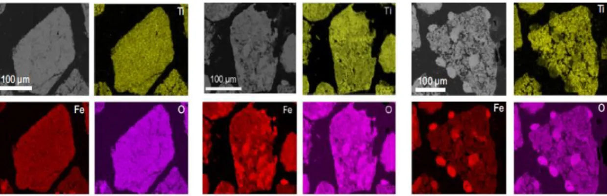
Fig. 13. SEM images of a) details of the external surface, b) details of the cross section inside the particles and c) cross section of a particle for pre-oxidized ilmenite, after 3 cycles and
after 13 cycles using coal char as fuel [58].
Ilmenite was also used in a system of coupled fluidized beds for CLC where lignite was used as reducing gas. The ilmenite was used for 60 hours operation. The activation of ilmenite occurred during the process and the combustion efficiency increased whereas the oxygen demand decreased. As mentioned before, it occurs because of changes in structure of particle surface. The effect of operation parameters was reported and it has shown that increasing the temperature of fuel reactor led to decrease in the unconverted gases released from the fuel reactor. This means that the reactivity of ilmenite is enhanced during the process [60].
The acceptable performance of the ilmenite was observed when it was used in the two-stage bubbling fluidized bed and lignite was used as fuel. The two fluidized beds were the fuel reactor and the riser of the circulating fluidized bed, as the air reactor. The fuel reactor includes two bubbling fluidized bed stages in order to be installed above each
19
other. The main idea of the design of the two-stage reactor is that the solid fuel is introduced in lower bed. In this stage, most of the conversion is occurred and solid fuel is gasified and then the combustible gases and solids contact with fresh oxygen carrier to increase the conversion. Evaluations of the compositions of first and second stages showed that the amount of CO2 concentration increased from 55 to 83 vol.% meanwhile concentration of CO, H2 and methane decreased. It means that the second stage had a positive effect on the total conversion [61]
The effect of bituminous and lignite ash layer on the performance of ilmenite was shown by Azis et al. [62]. Experiments were taken place in a fluidized bed reactor. The main solid fuel was bituminous coal and lignite. The size of the coal particles was in rang of 125-180 m, same as the ilmenite particle size. The activated ilmenite was used with lignite and bituminous coal and methane. The specific amount of ash was introduced into the reactor in order to determine its effect on the behavior of oxygen carrier. Addition of ash showed positive affect on gas conversion of both coal and methane.
Fig. 14. Concentration profile of the 49th cycle of ilmenite (last cycle) with Chinese bituminous mixed with 33.3 wt.% of coal gasification ash [62].
20
Ilmenite was used as an oxygen carrier in a 500 kWh CLC process while the bituminous coal used as fuel. During this process, the effect of reducer temperature variation was considered. The results showed that the combustion reaction and gasification were faster at higher temperatures (Figure 15). In addition, carbon capture and combustion efficiency were higher at high temperature. Only a small amount of CH4 was observed during the process. The coal particle size had little effect on the coal conversion. Ilmenite was activated after 3 hours during the reduction reaction [63].
Berguerand et al. [28] used ilmenite with two types of coal from different regions; Mexican petroleum coke and African bituminous coal. The temperature of the reactor reached around 1030 C. The aim of their investigation was to study the conversion of ilmenite with coal and design a model for this conversion. Increasing the temperature had positive effect on the gas conversion. The results are illustrated in Figure 16.
21
Fig. 15. a) Char conversion, b) carbon capture and c) combustion efficiency variation with fuel-reactor temperature for various coal particle sizes. Particle size: () 74–125 m; c) () 125–200 m; (□) 200–300 m. (d, e, f) CO2, CO and H2 concentration in the fuel-reactor (dry
free N2 basis) at different fuel-reactor temperatures for different coal particle size. Particle size: () 74–125 m; () 125–200 m; (󠇅□) 200–300 m. (g) Oxygen demand variation with
22
Fig. 16. a) Hydrogen conversion γH2 against degree of mass-based conversion for different temperatures b) Carbon monoxide conversion against degree of mass-based conversion for
different temperatures [28].
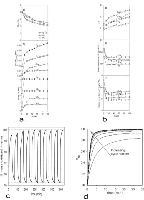
The performance of ilmenite was assessed in a 100 kWh chemical looping combustor, using biochar as fuel. The porosity of ilmenite increased from 10 % to 50 %, because of the iron active phase tends to mitigate to regains, which have high oxygen potential. Mitigation of iron phase is faster than that of titanium oxide in ilmenite (Fig. 17). Moreover, it can increase the reactive surface of ilmenite. It means that the surface area of ilmenite was increased during this process because of increasing the porosity of ilmenite [64].
Fig. 17. Elemental maps of Fe (red), Ti (yellow) and O (pink) on three representative particles varying in porosity and morphology. Measured porosity is increasing in the
23
Ilmenite was used for 11 hours under stable conditions in the CLC process with Mexican petroleum coke and African coal used as fuel. The CO2 capture of Mexican coal was lower than that of the African coal. No agglomeration or attrition was found when Mexican coal was used [65].
Ilmenite was also used as an oxygen carrier with fuels containing different levels of sulfur; sulfur-free kerosene and sulfurous kerosene. The CO2 yield, gas conversion and reactivity of ilmenite with two fuels were assessed and results showed that both fuels could reach a CO2 yield close to 99 % (Figure 18). Moreover, reactivity of ilmenite with sulfurous kerosene was higher than its reactivity with sulfur-free kerosene due to the positive effect of sulfur on the reactivity of ilmenite [66].
Fig. 18. Comparison of experiments two fuels, free-sulfur and sulfurous kerosene [66].
The environmental effect of Fe-based oxygen carriers is another aspect of the CLC technology. The coal particles used in the CLC operation must be non-toxi. Three Fe-based oxygen carriers were selected for the experiments; ilmenite, bauxite waste and iron ore. The results of leaching tests showed that ilmenite, as a Fe-based oxygen carrier, is stable. These results showed that ilmenite is one of the environmentally friendly components after the CLC operation with coal [67].
24
Ilmenite was used for analytical model of gas conversion of CLC when coal was used as fuel [68]. The CFD model was designed for outlet gas concentration of CH4, CO and CO2. The data used in this study picked up from the study of Leion et al. [69] about the ilmenite reactivity when CH4 was used as fuel. This model could predict the outlet gas concentration from reducer reactor. Figure 19 shows the results of the CFD model.
Fig. 19. a) Velocity vectors (m/s) and volume fractions of iron oxide and coal particles at 175 s, temperature of 1273 K and 50 % steam concentration. a1) Iron oxide and a2) Coal. b) Instantaneous gas species mass fractions at 175 s, temperature of 1273 K and 50 % steam concentration. b1) H2O, b2) CO2 and b3) H2. Gasification rate of char (kmol / (m3 s) of char).
25
Ilmenite has shown good reactivity with CO and H2 as reducing gas in 10 cycles. The oxygen transport capacity was 5.52 % after 30 min of reduction cycle. The complete reduction curve of ilmenite is shown in Figure 20a. The results of chemical stability of ilmenite using 10 redox cycles in TGA are shown in Figure 20b [70].
Fig. 20.a) Complete reduction of ilmenite b) TGA test of 10 redox cycles, particle size 150-250 μm, T=950-1050C [70].
The behavior of two types of ilmenite, raw ilmenite and 10 wt.% K+ promoted ilmenite (prepared through the wet impregnation method), was investigated for 100 hours continuous operation in a dual fluidized bed reactor [71]. The surface area of raw ilmenite was 0.64 m2/g. The raw ilmenite showed lower reactivity when CO used as fuel. Only 60 % of CO converted but the conversion increased to 78.5 % with potassium addition. The results showed that increasing the temperature did not affect the reactivity of ilmenite with 10 wt.% of potassium. Both materials have shown to be resistant to agglomeration during the CLC process. The results showed good mechanical properties and stability of oxygen carriers in the process.
Ridha et al. [45] studied the reduction of the ilmenite with CO in a pressurized isothermal CLC. Some raw ilmenites were calcined before the experiments. The
26
calcined ilmenite showed higher surface area than did the raw ilmenite. The surface morphology of the raw and calcined ilmenite is shown in Figure 21. Moreover, the calcined ilmenite exhibited a pore volume three times higher than raw ilmenite. The higher pore volume of the calcined sample was believed to improve its reactivity. The porosity of ilmenite after reduction reaction was higher than its porosity after oxidation reaction. In addition, increasing the pressure of CO did not significantly affect the morphology of ilmenite
Fig. 21. Surface morphology of ilmenite ore; a) raw ilmenite and b) calcined ilmenite [45].
Five different types of ilmenite (Norwegian rock ilmenite, African sand ilmenite, raw sand ilmenite from Madagascar, Canadian raw hemo-ilmenite and upgraded kiln treated ore (UkTO)) were tested for syngas combustion. Overall, due its higher content of active phase, the rock ilmenite was better than the sand ilmenite in the CLC process.
27
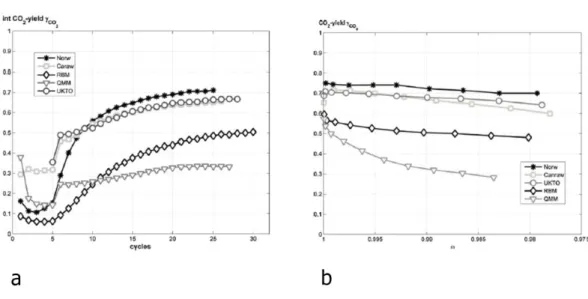
The water gas shift reaction had positive effect on the reduction reaction of ilmenite and it leads to increase the CO2 conversion. The African ilmenite has shown lower reactivity than other ilmenites (Figure 22) [72].
Fig. 22. a) Integral CO2-yields during reduction with syngas (H2/CO-50/50), b) CO2 yield during reduction with syngas (H2/CO-50/50) for the last cycle as a function of oxygen carrier
conversion (ω) [72].
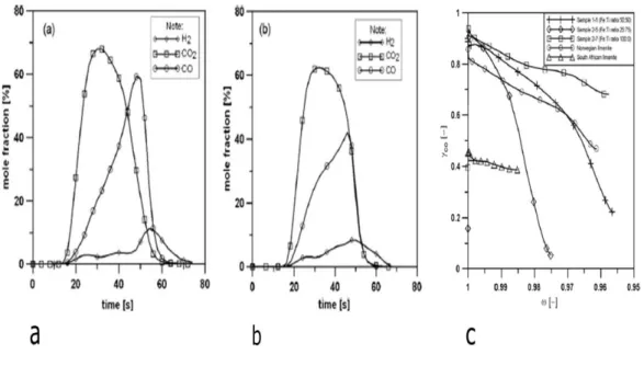
Natural ilmenite and synthetic ilmenite were compared by Azis et al. [73]. The synthetic ilmenites were prepared in different Fe:Ti ratios. One of the synthetic ilmenites was mixed with quartz. All samples were tested with syngas in the CLC process. The samples, which had a higher Fe:Ti ratio, have shown higher reactivity due to increasing the active phase. Figure 23 shows the results.
Abad et al. [75] studied the reactivity of ilmenite with H2 and CO. One reduction cycle was considered for eight minutes. A 50 mg sample was used and the reducing gas was H2 and CO. The oxidation of each sample was taken place with air for 5 minutes. The effects of H2O/H2 was investigated and the results showed that this ratio could improve the reactivity of ilmenite with syngas. The results are illustrated in Figure 24.
28
The effect of coke as reducing agent in the reducer reactor was investigated by Teyssi
et al. 2011 when ilmenite was used. The particle size of ilmenite was (125-180 μm)
whereas the particle size of limestone was (180-250 μm) when it mixed with ilmenite. This mixture could improve the conversion rate of char and gas conversion [75].
Fig. 23. The mole fraction (dry gases) for the last reduction period (a) synthetic ilmenite (50 % Fe and 50 % Ti) and, b) natural Norwegian ilmenite, c) Conversion of CO as a function of the mass-based conversion of the oxygen carriers (ω) for three of the synthetically produced
29
Fig. 24. Thermograms obtained during the reduction of activated ilmenite using different H2O/H2 ratios at 1173 K [75].
According to the previous studies [49,56], it is clear that ilmenite does not completely react with CH4 as reducing gas. Obviously, this problem decreases the reactivity of ilmenite during the CLC process and releases most of the CH4 in the atmosphere. As Figure 25 shows, most of methane passes through the system without reacting with the ilmenite. The concentration of CO2 in the outlet gas reaches the maximum after a few seconds of starting the experiment. The BET surface area also increased from 0.11 m2/g for fresh particles to 0.28 m2/g for used particles due to increasing porosity of ilmenite during the reduction reactions [60].
30
Fig. 25. a) Variation of the oxygen transport capacity, normalized reactivity, rate index with the number of redox cycles solid conversion variation, c) Mass variations d) Normalized
conversion during the oxidation reaction [60].
Cuadrat et al. 2012 showed that ilmenite exhibits a good mechanical strength in the CLC process. The initial reactivity of ilmenite is low but it undergoes an activation process after a few cycles (Figure 26) [76].
31
Fig. 26. Profiles of CO2 or H2O fractions in the product gas (wet basis) during consecutive reduction periods, for a) CH4, b) CO and c) H2 as reducing gases (D). Oxygen yield, [76].
Pröll et al. [77] studied the effect of natural olivine in the conversion of hydrocarbon when ilmenite used as oxygen carrier. The results showed that the reactivity of ilmenite with CH4 was increase. The results are shown in Figure 27.
The reactivity of ilmenite was also compared with Fe2O3/MgAl2O3 when syngas was used as fuel. Both of them have shown high reactivity with H2 and CO and they have not shown agglomeration in the process. Both carriers were used when coal used as fuel. The conversion rate of coal increased with increasing the fraction of steam in the fluidizing gas (Figure 28). The influence of reducer temperature was investigated as well. As the results showed, increasing the reducer temperature positively affected the reactivity of ilmenite [56].
32
Fig. 27. Fuel conversion a) and CO2 yield b) for 100 % natural gas operation with different solids inventories. Ratio CO/CO2 (c) and ratio H2/CO d) in fuel reactor exhaust gas for
33
Fig. 28. a) Concentration profile during the reduction of 40 g Fe2O3/MgAl2O4 with 0.2 g petroleum coke. The inlet concentration of H2O is 50 %. The temperature is 950 C. b) Concentration profile during the reduction of 40 g ilmenite with 0.2 g petroleum coke. The
concentration of H2O is 50 %. The temperature is 950 C [56].
1.6 Issues encountered with oxygen carriers
The oxygen carriers may suffer from activity loss during service. This process is basically due to two phenomena: agglomeration and attrition, resulting in changes of particle size distribution and active surface area. In addition, the size of the particles is of great importance for fluidizability. Too large particles are not fluidizable and too small ones are entrained out with the carrier gas.
The particle agglomeration occurs in chemical looping process when chemical looping system has two interconnected reactors. The NiO-based oxygen carrier does not agglomerate in chemical looping system normally in the typical temperature of 950 °C. Johansson et al. [78.79] showed that calcination temperature and metal quantity are important factors to agglomeration tendency. For Fe-based oxygen carrier, the particle agglomeration depends on reactivity of oxygen carrier in the fuel reactor. For Cu-based carriers, the tendency of agglomeration is higher due to the low melting point of Cu (1085 °C).
The attrition of oxygen carrier in CLC system affects the performance and the overall cost of oxygen carrier. The attrition of oxygen carrier is defined as reducing the
34
mechanical strength or losing the part of the oxygen carrier due to fragmentation and crushing when the oxygen carrier is used in chemical looping system. So, the metal oxide must have low attrition tendency in the CLC process. For example, Ni-based oxygen carrier with Al2O3 as support has shown low attrition rate during the CLC process or micaceous iron oxide has shown attrition problem when it is used in CLC process [20].
Another important parameter for oxygen carrier is its lifetime. The lifetime is defined as the mean time that a particle must be under the reduction and oxidation reactions in the system without any reactivity loss or without suffering the attrition or fragmentation processes. The published results in the literature showed that Ni-based oxygen carrier has long time lifetime in comparison with other oxygen carriers [81].
Fluidizability of the oxygen carrier is also a significant parameter in the CLC system. If the mean particle size is in the range of 40 m dp 500 m and the density is in the range of 4 g / cm3 and 1.4 g / cm3, powder can easily fluidized in the CLC system [81].
1.7
Cost of oxygen carrier
One of the significant factors to choose a proper oxygen carrier is its cost . The cost of the oxygen carrier includes the inert support, the cost of metal oxide and manufacturing cost. In the industrial scales, the manufacturing cost is very low and the cost of oxygen carrier depends on the raw materials. Nickel and cobalt are the expensive materials, while manganese and iron are cheaper. The importance of the oxygen carrier’s cost is determined when these materials are used in the industrial scale. Ilmenite is proposed in this work as a low-cost and abundant source for oxygen carrier.
1.8
Hypothesis and objectives of thesis
In this research project, ilmenite was chosen as oxygen carrier. The ilmenite is a natural and abundant mineral with a typical chemical formula of FeTiO3. The iron oxide in ilmenite (FeO.TiO2) behaves as active phase, which plays the role of oxygen carrier. It is a promising oxygen carrier for gaseous fuels in chemical looping combustion (CLC). The initial reactivity of ilmenite is low but it undergoes an activation process after several cycles. The reactivity of ilmenite as an oxygen carrier in chemical looping
35
combustion was lower when CH4 was used as fuel (23, 24). This project attempts to verify and improve the reactivity of ilmenite when CH4 is used as fuel in CLC process.
The previous studies showed that the addition of doping elements can improve the reactivity of ilmenite when CH4 is used as fuel gas. Ryden et al. [49] showed that addition of low weight percent of NiO particles to the ilmenite improved its reactivity. The addition of limestone could also increase the reactivity of ilmenite in chemical looping combustion.
Our hypothesis is based on increasing the reactivity of ilmenite by increasing its specific surface area and adding NiO as doping agent. Therefore, the combination of these two approaches would rather enhance the reactivity of ilmenite. High Energy Ball Milling will be used to decrease the crystal size of natural ilmenite. Low Energy Ball mill will be used to increase the specific surface area of the milled ilmenite. High Energy Ball Milling provides also the opportunity to incorporate NiO into the ilmenite matrix and produce nano-size particles at the same time.
The project objectives can be summarized as:
a) Detailed studies of ilmenite application as an oxygen carrier in chemical looping combustion.
b) Increasing the specific surface area of pure ilmenite.
c) Doping the nanostructured ilmenite with NiO and optimizing the doping level and process.
36
Chapter 2: Methodology
Regarding the problem statement, the reactivity of ilmenite with methane is lower than syngas. For increasing the reactivity of ilmenite with methane, the surface area of ilmenite will be increased and the NiO particles will be added to ilmenite by High Energy Ball Milling. Low Energy Ball Milling (Attrition Mill) can increase the specific surface area of both oxygen carriers. The XRD and BET tests will be used to characterize the samples. The reactivity of oxygen carriers will be tested by the TGA. The analytical techniques are described in the next section.
Where does the ilmenite come from?
2.1
High Energy Ball milling
Mechanical milling is a good method for industrial production of nanostructured materials. The energy transferred from the balls to the powder can be controlled by milling speed, size of the balls, ball-to-powder ratio, and time of the milling [82].
For High Energy Ball Milling, 7 g of pure ilmenite was charged in a steel vial with three steel balls. A SPEX-800 mill was used for this purpose. Seven samples were prepared at different milling times (0, 15, 30, 60, 90, 120, 180 minutes). The purpose of this experiment is to decrease the particle size of ilmenite. To characterize the mineral structure and also to determine the crystal size of these samples, X-ray diffraction (XRD) was used. The preliminary results of ball milling process are reported in Chapter 3.
To mix the nickel oxide particles into the natural ilmenite matrix, the High Energy Ball Milling approach was used. For this purpose, 7 g of ilmenite with different weight percent of nickel oxide were charged in a steal vial and milled for 2 hours. Then X-ray diffraction was applied to make sure that the nickel oxide has been integrated into the ilmenite.
37
2.2
Low Energy Ball Milling (Attrition Mill)
The attrition mill involves vertical drum, small balls and a turning shaft at the middle. The energy of motor is transferred to the balls by the turning shaft and the balls turn in the same direction as the shaft. The centrifuge force is produced by rotation of the shaft, pushing the balls toward the drum wall, rising along the wall and falling down into the drum [82].
A Union Process attrition mill (1 L capacity) was used to increase the specific surface area of pure and mixed ilmenite. A sample milled in High Energy Ball mill is highly agglomerated. The attrition mill can deagglomerate the milled powder and produce fresh surfaces. By using the attrition mill, the surface area of ilmenite can be increased by 5 to 6 times. One of the original aspects of this project is to increase the surface area of ilmenite to reach higher reactivity. For increasing the specific surface area of oxygen carriers, 2 hours of attrition milling was considered for the LEBM step.
2.3
BET analysis
BET analysis was used to determine the specific surface area of the powder samples by physical adsorption of a N2 gas on the surface of the solid and calculating the amount of adsorbate gas corresponding to a monomolecular layer on the surface. Removing the gases and vapors that may have become physically adsorbed onto the surface is necessary before the specific surface area of the sample can be determined. If some gasses or vapors exist, the specific surface area reduces or varies because a fraction of the surface is covered with molecules of the previously adsorbed gases or vapors.
In this research, the surface area of samples was determined using a Micromeritics instrument. The samples were degassed at 200 C for 6 h in order to remove physiosorbed gases or water vapor.
2.4
X-ray diffraction
The X-ray diffraction instrument has three basic components: X-ray source, specimen and X-ray detector. Theta (Bragg angle) is the angle between the plane of the specimen and the X-ray beam. 2ϴ is the angle between the projection of the X-ray beam and the detector. The X-ray source is fixed and the detector goes around over a range of angles.
38
The range of 2ϴ is typically between 0 and 170 degrees. The measurement range typically depends on the crystal structure of material but normally the range of the 2ϴ is between 0 - 120 degrees. If the specimen is unknown, a large range of angles is used. The peak intensity plots on the ordinate Y-axis and the 2ϴ angle plots on the abscissae X-axis. Each peak corresponds to X-ray diffracted from a specific set of planes in the specimen.
Patterns were collected using a SIEMENS D5000 diffractometer, operating with CuKα radiation (λ = 0.154 nm) as X-ray source. Recording is performed for 2 between 10° and 80° (step time = 2 s; step size = 0.04°). Crystal domain size (Dcryst) is evaluated by means of the Scherrer equation, Dcryst=Kλ/βcos(󠇅θ), after Warren’s correction for instrumental broadening. K is a particle shape constant and λ is the wavelength of the X-ray used. β is the effective line width of the reflection (󠇅β2= B2-b2, where B is the FWHM and b is the instrumental broadening determined by the FWHM of the reflection of quartz at 2θ ≈ 27°).
2.5
Thermogravimetric analysis (TGA)
Thermogravimetric analysis (TGA) is a thermal analysis method that can measure the changes of mass of samples during heating cycles. TGA can record changes in mass from dehydration, decomposition and oxidation/reduction of a sample with time and temperature. The results are plotted as mass change versus temperature or time. The Y-axis is normally the weight change in percentage and X-Y-axis is normally time or temperature.
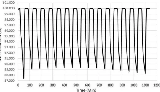
In this research, the thermogravimetric analysis of samples are determnied using a Netzsch instrument (Netzsch STA 449 F3 Jupiter, Germany), equipped with a rhodium furnace and an analytical balance (0.002 mg). For this purpose, 30 mg of each sample was loaded in the TGA basket and the system was heated to 900 C under a N2 gas. Then the experiment was started to alternating reducing and oxidating conditions. Methane was used as the reducing gas for 10 minutes and then air was used for oxidation reaction for 10 minutes. Between each reduction and oxidation reaction, a nitrogen flow was passed for 5 minutes for avoiding contact between methane and air. Overall sixteen cycles were done and the reactivity of oxygen carriers was determined.
39
The amount of weight loss and rate of each reaction are important parameters to determine the reactivity of each materials.
2.6
Data Evaluation
The oxygen transport capacity of the ilmenite, ROC, is defined as the mass fraction of the oxygen that can be used in the oxygen transfer and calculated according to Equation 2-1 [49]:
𝑅𝑜𝑐 =
𝑀𝑜𝑥− 𝑀𝑟𝑒𝑑
𝑀𝑟𝑒𝑑 (Equation 2-1)
Mox = Mass of the most oxidized state of oxygen carrier
Mred = Mass of the most reduced state of oxygen carrier.
Degree of conversion, X, of the oxygen carrier is used to quantify the conversion of the oxygen carrier and is defined as [56]:
𝑋 =
𝑀−𝑀𝑟𝑒𝑑𝑀𝑜𝑥−𝑀𝑟𝑒𝑑 (Equation 2-2)
M = Mass of the oxygen carrier.
Mred = Mass of the oxygen carrier in its most reduce state.
Mox = Mass of the oxygen carrier in its oxidized state.
The degree of mass-based conversion, ω, is used as it is convenient for comparison of different materials and is defined as [56]:
𝜔 =
𝑀 𝑀𝑟𝑒𝑑40
Chapter 3: Results and discussion
3.1
Physical characterization
3.1.1 X-Ray diffraction measurement of samples
The X-ray diffraction patterns of the un-milled and milled ilmenite samples (FeTiO3) are shown in Figure 29. Un-milled ilmenite is identified as 0-min sample. In this sample, two phases were determined by X-ray, which are ilmenite (FeTiO3) and magnetite.
The diffraction patterns of the milled samples show that the main peaks are still present after milling up to 180 min (Figure 29). This suggests that the High Energy Ball milling does not alter the chemical composition or crystalline structure of the samples. However, it can be seen that by increasing the milling time, the peaks are broadened while their intensity are decreased. The peak broadening is an indication of the decrease of crystal domain size.
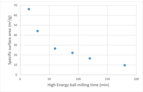
The crystallite domain size of the samples was determined by Debye-Scherrer equation, which is related to the X-ray diffraction line broadening. The crystallite domain size is represented in Table5. The variation of the specific surface area as a function of high-energy ball milling time is shown in Figure 30. The crystallite domain size of the un-milled ilmenite sample was higher than 100 nm. In this size range, the precise calculation of the crystallite size is not possible from X-ray patterns. The mean crystallite size was decreased down to 66 nm after 15 minutes of milling. After 180 minutes of milling, the crystallite size was decreased down to 9.6 nm. Although the rate of crystallite size refinement drastically decreases after one hour of milling, a plateau has not been completely reached after 180 minutes of milling. We did not further increase the milling time for two reasons: 1) increasing the milling time increases also an eventual production cost, 2) the level of contamination by milling media increases while using excessive milling times.
42
Figure 29: X-ray diffraction patterns of ilmenite samples. Samples were ball milled from 0 min to 180 min. The reference peaks of Ilmenite and Magnetite are presented at the bottom of
the graph.
Figure 30. Variation specific surface area as a function of high-energy ball milling time.
Table 5. The crystallite domain size of the samples
Milling time (min) Crystal size (nm) 0 66.2 15 44.13 30 26.48 60 22.06 90 16.55 120 9.67 180 9.62
Decreasing the crystallite size of ilmenite gives the opportunity to increase its specific surface area. In fact, by decreasing the crystallite domain size, the external surface of a powder grain is supposed to increase. However, as will be discussed in the following
0 10 20 30 40 50 60 70 0 50 100 150 200 Sp ecif ic su rf ace ar ea (m 2 /g)
43
sections, the surface area of the milled powder does not increase significantly by High Energy Ball Milling. This is due to the fact that the as-milled powders are highly agglomerated. The external surface of each grain is thus attached to the nearby particles and becomes the grain boundary, rather than the free surface. To increase the accessible surface, the particles must be further deagglomerated.
As Ryden et al. [49] reported, the reactivity of ilmenite can be increased by addition of nickel oxide. High energy ball milling provides an opportunity for addition of nickel oxide to ilmenite. So, to dope ilmenite with nickel, we used high energy ball milling. First, ilmenite was milled for 180 min. Then, nickel was added to this sample in the form of nickel oxide (NiO) with particle size of 50 µm. The main reason for choosing 180-min sample is that the specific surface area of 180-min ball milled ilmenite was the highest (Fig. 30 shows exactly the opposite) and its crystal size was lower than that of the other samples. As the powder mixture had to be further ball milled, the size of the NiO particles was not of great importance.
Three levels of nickel addition of 2, 4 and 8 wt. % were used. Figure 31 shows the X-ray diffraction patterns of the samples containing 4 and 8 wt. % NiO. Two phases are identified by the diffraction patterns, i.e. ilmenite and NiO. The intensity of NiO peaks increases by increasing the concentration of NiO. This indicates that no reaction occurred between NiO and ilmenite during high energy ball milling. The broad peaks of NiO also suggest that its crystallite domain size is less than 100 nm. The high energy ball milling results in homogeneous dispersion of NiO particles within the ilmenite particles. Due to the small size of NiO particles, their diffraction patterns are not detectable at lower concentrations. The last sentence is a bizarre statementand should be modified
![Fig. 2: Oxygen transfer capacity of different oxygen carriers [12].](https://thumb-eu.123doks.com/thumbv2/123doknet/3739471.112417/14.892.232.652.409.693/fig-oxygen-transfer-capacity-different-oxygen-carriers.webp)
![Fig. 8. Comparison of bed feed using ilmenite and bituminous coal as fuel [52].](https://thumb-eu.123doks.com/thumbv2/123doknet/3739471.112417/23.892.187.703.115.547/fig-comparison-feed-using-ilmenite-bituminous-coal-fuel.webp)
![Fig. 18. Comparison of experiments two fuels, free-sulfur and sulfurous kerosene [66]](https://thumb-eu.123doks.com/thumbv2/123doknet/3739471.112417/33.892.258.614.544.833/fig-comparison-experiments-fuels-free-sulfur-sulfurous-kerosene.webp)
![Fig. 24. Thermograms obtained during the reduction of activated ilmenite using different H 2 O/H 2 ratios at 1173 K [75]](https://thumb-eu.123doks.com/thumbv2/123doknet/3739471.112417/39.892.287.619.113.407/thermograms-obtained-reduction-activated-ilmenite-using-different-ratios.webp)