Science Arts & Métiers (SAM)
is an open access repository that collects the work of Arts et Métiers Institute of Technology researchers and makes it freely available over the web where possible.
This is an author-deposited version published in: https://sam.ensam.eu Handle ID: .http://hdl.handle.net/10985/11409
To cite this version :
Katia LUPINETTI, Franca GIANNINI, Marina MONTI, Jean-Philippe PERNOT - CAD assembly descriptors for knowledge capitalization and model retrieval - In: Tools and Methods for
Competitive Engineering (Aix-en-Provence : 16 : 2016), France, 2016 - Proceeding of Tools and Methods for Competitive Engineering - 2016
Any correspondence concerning this service should be sent to the repository Administrator : [email protected]
CAD ASSEMBLY DESCRIPTORS FOR KNOWLEDGE CAPITALIZATION AND
MODEL RETRIEVAL
Katia Lupinetti1,2
1Istituto di Matematica Applicata e Tecnologie Informatiche “E. Magenes” 1Consiglio Nazionale delle Ricerche
2Arts et Métiers ParisTech LSIS Laboratory [email protected]
Franca Giannini1 Marina Monti1
1Istituto di Matematica Applicata e Tecnologie Informatiche “E. Magenes” 1Consiglio Nazionale delle Ricerche
[email protected] [email protected] Jean-Philippe Pernot2
2Arts et Métiers ParisTech LSIS Laboratory [email protected]
1. ABSTRACT
Today, there exists a huge amount of digital data easily downloadable from Internet and/or simply accessible from large databases. Despite this rise, the methods to retrieve and search for specific data have not been sufficiently studied and developed, notably when considering 3D contents. Thus, it is sometime more efficient to define new 3D shapes starting from scratch rather than to try to make use of existing ones hardly identifiable within those da-tabases. This is particularly true when considering CAD assembly models often resulting from a long and time-consuming modeling phase within the Product Development Process. Thus, having new methods, models and tools to capitalize, retrieve and reuse CAD assembly models would help saving a lot of time. This paper addresses such a difficult prob-lem of finding a method to characterize and structure CAD assemblies so as to be able to search for similar ones. A framework has been designed for the retriev-al of globretriev-ally and/or partiretriev-ally similar assembly mod-els according to different user-specified search crite-ria. It is based on an assembly descriptor, called the Enriched Assembly Model (EAM), which encodes all the required data automatically extracted from the geometry and structure of the CAD models. The data are organized in several layers thus enabling multi-level structuring and queries. It also allows fuzzy queries, which can be further refined.
KEYWORDS
Assembly representation, assembly retrieval, multi-layered search, multi-modal descriptors.
2. INTRODUCTION
CAD models have become mainstream in many in-dustrial applications. They can be considered as digi-tal product reference models stored within a Digidigi-tal Mock-Up used and shared all along the Product De-velopment Process [6]. Over the last few years, CAD model databases grew up so much that it has become challenging to develop new searching and browsing methods and tools. This is notably true for what con-cern the structuring, the access and the reuse of those databases. Actually, being able to reuse existing in-formation and data, including existing 3D models, became a crucial factor for the competiveness of the industries whose behavior is often driven by the well-known triptych cost-quality-delay. Being faster in developing or releasing new products is a key issue. During the design process of a new product, the abil-ity to retrieve existing models, either parts or assem-blies, can be useful to reach several objectives as reusing an existing assembly in new configurations, or providing access to existing design knowledge (e.g. simulation results, manufacturing phases) relat-ed to similar products [8] or to identify similar con-figurations that could benefit from a standardization. However, such a retrieval process is not straightfor-ward when considering CAD models potentially
made of several hundreds of thousands of parts. Thus, specific search techniques have to be devel-oped and optimized to be able to retrieve elements in a reasonable time.
In simple text-based retrievals, the user types a list of words or sentences that he/she wants to search in the database. However, with this technique, some models are not retrieved, even if they are semantically related with the query since they have not the same text in their annotations. These limitations may be overcome by using search methods based on thesauri, i.e. col-lections of controlled vocabulary terms that use asso-ciative relationships. However, these techniques are not sufficient since annotations may not be present and there is no guarantee of compliance to name conventions; moreover, they do not consider the shapes of the parts.
Anyhow, in case of complex products made of sever-al parts a method based only on the shape is not suf-ficient for retrieving the target assembly model. Ac-tually, 3D models with similar shapes can be assem-bled in different ways, involving different kinematic characteristics and then different relationships be-tween their parts. For example, an assembly of two parts with 5 screws can be considered similar to the same assembly with 6 screws. In this case, at a higher level, what is important is that the two parts have been screwed whatever the number of screws. Thus, an advanced search method has to incorporate mech-anisms working at different levels (e.g. geometry, kinematic, annotation).
For the effective re-use of existing models, content-based methods should also allow queries without the specification of a CAD model as input. This possibil-ity is particularly important since at the early design stage, the designer would be interested in expressing vague queries, e.g. simply by specifying some attrib-utes of the assembly model, just to take inspiration from the available models. Therefore, the challenge is to find an assembly representation able to support user requests at different level of specification details but also that is automatically defined. Indeed, to re-quire the user to add manually some information may represent a heavy limitation.
In this context, it is crucial to provide a tool for the retrieval of assembly models which can be tailored to the user needs, and thus, that is able to consider the assembly and the part shapes, the interlinks between sub-assemblies and parts and other aspects that are implicitly stored in the 3D data.
In this paper, we propose a framework for the
re-trieval of globally and/or partially similar assembly models according to different search criteria that can be convenient for designers. It is based on an assem-bly descriptor, called the Enriched Assemassem-bly Model (EAM), which encodes all the required data extracted by analyzing the geometry and structure of the CAD model without user intervention. It allows fuzzy que-ries, which can be further refined and applied on search results. Section 2 reviews the related works. The EAM model is introduced in section 3 and the complete framework in section 4. The last section ends this paper with some conclusions and perspec-tives.
3. RELATED WORKS
Gupta et al. have categorized the various use scenari-os for content-based assembly search as follows [8]: • Design reuse. The retrieving of an existing similar model allows the designer to make modifications to it and to obtain faster a new product.
• Accessing the related existing knowledge. The availability of information related to similar mod-els (e.g. costs, reliability and failure reports, shape adaptation processes for simulation and analysis results) makes easier the evaluation of the new product solutions.
In addition to these use cases, one can also imagine having mechanisms to identify similar CAD models in order to be able to standardize parts or assemblies. In literature, a lot of works focuses on part retrieval. Tangelder and Veltkamp [16] and Iyer et al. [9] pro-vide a complete state-of-the-art on 3D shape retriev-al. However, these techniques focus on shape charac-teristics and do not take into account other important aspects for assembly models’ similarity, such as the relationships between the parts and are not able to retrieve similar assembly structures or more simply a sub-assembly in another assembly.
There are various works addressing the analysis of assembly models for diverse objectives, such as the identification of assembly constraints or the assembly sequence planning; only a limited set of works direct-ly addresses the search for assembdirect-ly models similar to a given one.
To the purpose of our research, we identified some useful criteria for a comprehensive analysis of the works directly or indirectly addressing the identifica-tion of similarities in assembly models under differ-ent perspectives. The adopted criteria can be grouped into the following macro-categories:
• type of information exploited, • type of assembly descriptors defined, • query model.
The context includes the work objectives and the required type of input data (i.e. B-Rep, 3D mesh or point cloud). The type of information refers to the information (i.e. geometric and/or topological in-formation) the authors use to characterize the as-sembly model. Either this information can be implic-itly coded in the input data or it can be explicimplic-itly associated to it. Moreover, it specifies if the assem-bly relationships (i.e. the relationships between the assembly components) are explicit in the CAD native models, automatically derived from assembly geome-try or specified by the user.
The type of assembly descriptors includes indications on the assembly description level, i.e. (i) assembly level: the assembly is described by its parts and/or their relationships; (ii) part level: the assembly is described by its parts; (iii) feature level: the assembly is described through shape portions having specific assembly meaning. Moreover, it indicates how the assembly descriptors are implemented, i.e. the de-scriptor representation used to store the infor-mation, such as graph or vector.
The query model indicates the type of data required to express the query (i.e. a single CAD assembly model, a set of CAD assembly models, a set of CAD part models such as a sub-assembly without the con-straints, a 3D mesh, or an abstract assembly
de-Paper Input model objective Work topological infor-Geometric/ mation used Assembly relation-ships Assembly descriptor level Descriptor represen-tation Query model [20] B-Rep Search for frequent simi-lar sub-assembly models Curvature, Model components, Mating constraints Already existing in the CAD model Assembly Part Face Adjacency Graph Assembly model [10] 3D mesh Search for globally simi-lar assembly models
Model components none Part Component Vector Assembly model
[3] B-Rep Search for globally or partially simi-lar assembly models Model elements Mating constraints Degree of freedom annotation Partially
extracted Assembly Part Hierar-chical graph Assembly model [18] B-Rep Search for globally simi-lar assembly models Model elements Surface properties Contact relations Manually
inserted Assembly Part
Component attributed relation graph Assembly model [12] B-Rep Search for globally simi-lar assembly models Shape characteris-tics Mating constraints Already existing in the CAD model Assembly Part Attributed Assembly graph Assembly model [5] B-Rep Search for globally or partially simi-lar assembly models Model elements Mating constraints Degree of freedom Annotation Already existing in the CAD model Assembly
Part Mating graph
Set of statistics
Mating graph
scriptor).
Table 1 summarizes the analyzed works directly aimed at the retrieval of similar assembly models according to the above criteria. Among these works, only two adopt a more comprehensive approach [3, 5]. Deshmukh et al. take into account many different aspects that play a meaningful role in the description of an assembly product [5]. The main limit of the presented work is in the required availability of sev-eral important information (such as the component orientation, component relationships and the joint constraints). A global approach, which aims to over-come this limitation, is proposed by Chen et al. [3]. This work does not consider the overall assembly shape but focuses on the product structure and the relationships between the different parts of the as-sembly.
The assembly descriptor presented in this work takes into account different information levels. It includes topological structure, relationships between assembly components, and geometric information. It permits the use of rough and partial incomplete queries to allow a search completely adaptable to the designer requirements. The framework we propose is based on an assembly model that similarly to the ones present-ed in [3] and [5] is able to support user requests at different level of specification details but differently than [5] does not require the user to add manually some information. Differently than [3] the mapping algorithm is not limited to the identification of as-sembly models with the same structure in terms of sub-assemblies. Moreover, the framework does not rely on a specific CAD native file format, but re-quires as input a STEP file describing the assembly model, in which only geometric information is avail-able and allows the retrieval of assembly models of which the query model is a sub-set.
4. THE ENRICHED ASSEMBLY MODEL
In order to allow an efficient and meaningful retrieval of CAD assembly models, a suitable description of the assembly should be provided. As previously de-scribed, an effective reuse of already existing models requires the possibility to perform search with que-ries using incomplete information and involving characteristics which might be not explicitly encoded in the CAD models, but highlighting features valua-ble for the search purposes. To this aim in the follow-ing, we propose a new shape descriptor called En-riched Assembly Model (EAM), which organizes information in a multi-layer structure aimed at guar-anteeing the search flexibility. This permits search
queries involving one or several layers of infor-mation in various combinations. The considered lay-ers are: structural layer, statistic layer, shape layer and interface assembly layer.
4.1. Structural layer
The structural layer of the EAM encodes the hierar-chical assembly structure of the CAD model as speci-fied by the designer. At this level, information is stored as a tree graph in which arcs indicate the rela-tion part-of and nodes correspond to the assembly elements. In particular, leaves represent the parts of the assembly model, the root the entire assembly model, while intermediate nodes represent sub-assemblies of the original model. Attributes are asso-ciated to leaf nodes to indicate the type of the corre-sponding component: fastener (e.g. bolts, screws) and principal. Here, the rational is that not always the geometry of fasteners is fully specified but they may be simply indicated as annotations. Therefore distinguishing between principal shape components and fasteners allows to possibly discard the second ones during the comparison, thus permitting to focus only on the most specific parts of the assembly. Additionally, each component is classified as thin or
normal part, such that if the comparison among the
shape of the single components is required in the query, it can be performed only on compatible ones discarding the others. The thin part class includes different types of objects, such as those similar to thin plates, or having an arbitrary shape with almost constant thickness distribution, or presenting a large emptiness in its bounding box. Different criteria are used to distinguish the typology of thin objects as described in [14]. For subassembly nodes, we con-sider the shape resulting from the Boolean union operation performed on the subassembly compo-nents, such that a single object is obtained on which the classification into thin or normal part and the various shape descriptors are computed. Such an overall assembly shape is useful to guarantee the possibility of evaluating similar assemblies from the structural and shape point of view, such that sub-assembly can be treated as it were a single unique part. Such decomposition into parts, subassemblies or a single component resulting from the merging of all the parts and subassemblies also correspond to the way designers may focus on a product. Actually, designers can consider the product either as a whole object with its characteristics (e.g. volume, gravity center), or focusing on subassemblies (e.g. for kine-matics purposes) or parts (e.g. for manufacturing issues).
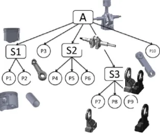
Figure 1 shows an example of the structural layer of an assembly model. The object is an engine formed by three sub-assemblies (S1, S2, S3): a piston, a crank shaft and a mass and two linking parts (P3, P10).
Example of structural layer of an assembly Figure 1
model
It is important to notice that the assembly decomposi-tion depends on the context and, even if it represents a semantic organization, it is not unique. For exam-ple, the assembly can be organized in a way that the forthcoming assembly simulation steps are eased, or it can be organized with respect to visualization is-sues according to an octree-based decomposition, or it can be decomposed according to criteria based on the constitutive materials. Therefore, assembly simi-larity cannot strongly require same structures if not specifically requested by the user. However, we be-lieve that there is a level of decomposition under which multiple decompositions of a same product will remain similar, and would in this case corre-spond to the smallest common denominators. Such an understanding can be performed at the level of the parts and subassemblies, but also at the level of the joints between the elements constituting the global assembly. This point is not further discussed in this paper.
Finally, all the elements in the tree are associated to data in the other information layer to fully character-ize them.
4.2. Statistic layer
This layer collects several information that can be represented in form of numerical values for allowing a quick search and filtering. Statistics referring to the overall assembly or to sub-assembly nodes are:
• number of sub-assemblies, • number of principal parts, • number of fasteners, • number of thin parts,
• number of linear patterns of repeated components, • number of circular patterns of repeated
compo-nents,
• number of reflective patterns of repeated compo-nents.
While statistics referring to the parts include:
• percentages of specific type surfaces (i.e. planar, cylindrical, spherical, free form, toroidal) with re-spect to the overall area,
• numbers of maximal faces (i.e. adjacent faces sharing the same underlying surface are consid-ered as a single face) of a specific type surface (i.e. planar, cylindrical, spherical, free form, to-roidal).
Statistics related to assembly interfaces are the num-ber of elements in contact for each type (e.g. planar pair, planar-cylindrical pair).
The inclusion of information related to the presence of patterns can support the search of similar models having similar manufacturing or assembly processes. Of course, based on this first list of statistics, addi-tional descriptors can be used to enrich the character-ization of the assembly model at different levels of the structural layer.
4.3. Shape layer
The shape layer includes the specification of the in-formation related to the shape of the elements in the assembly. Useful for their comparison, this layer can also be interesting for the visualization. In particular, for each node of the structural layer (both parts and sub-assemblies), two mesh representations are asso-ciated together with several shape descriptors. The first is a rather precise model, the second corresponds to its rough representation (e.g. convex hull or more simply its bounding box). These double representa-tions allow both a fast browsing of the objects and of the search results as well as the specification of both precise and rough queries with unprecise shapes. This is quite useful during product design when the shape is under development and it is quite reasonable to search for possibly re-usable products that share the main behavioral (e.g. degree of freedom) and overall shape characteristics. For each intermediate node (i.e. nodes associated to a sub-assembly), mesh-es and shape dmesh-escriptors are provided and computed as previously described.
The choice of considering different shape descriptors associated to a single shape is due to the fact that it has been demonstrated that there is no best shape descriptor for the comparison of each shape type [9]. On the contrary, depending on the type of object a specific shape descriptor performs better. In our model, we intend to consider descriptors related to both the overall component and to its shape variation. Among the descriptors of the first type, we consider the volume and the surface area, which are size de-pendent. The other shape descriptors considered for the nodes in the structural graph are the spherical harmonics and shape distribution, which perform well with prismatic parts and shapes of revolution of which are mostly composed the mechanical products we are considering [9]. Therefore, depending on the values related to the percentages of surface type of the component (at the statistic layer), the comparison is activated to the concerned descriptor or to a weighted combination.
4.4. Interface assembly layer
This layer encodes the relationships between the different parts in an assembly model regardless the assembly organization. Therefore, it consists of arcs linking leaf nodes. Links between sub-assemblies and the rest of the assembly components can be ob-tained by simply considering the arcs that do not join the sub-assembly components. The possible rela-tionships between two parts can be grouped into
con-tact, interference and clearance [15] as shown in
figure 2.
Two parts are in contact, if they touch along low-level geometric entities such as faces, edges or points without any shared volume. Two parts define an in-terference if a common volume exists between them. This relation cannot exist between two real objects, however during the modeling phase it may happen for instance after local shape simplification for simu-lation.
Possible relationships between parts Figure 2
Another possibility is due to some tolerances in the modelling, i.e. still at the intermediate design stage
where dimensions are not fully tuned or there are tolerance issues. Since interference should not exist in a correct assembly model, they are not included in the EAM and, if present, are treated as contact. Clearance occurs when the distance between two surfaces of two parts is meaningful for the considered assembly, i.e. it is a small non-null distance between two parts in the assembly. This case is rather ambig-uous since the design intent can correspond to both non-contact and contact configurations (i.e. due to tolerance problems).
The interface layer is itself a multilayered one. Clear-ance and contacts are further detailed in terms of the types of kinematic pairs between parts, i.e. number and types of geometric elements, which are (almost) mating. At the lowest level, the couples of geometric elements (points, edges or faces) in contact of the two parts are specified, while at the highest level these are classified according to the resulting assem-bly feature [19] obtained combining the effect of kinematic pairs. In particular, we classify the con-tacts and clearance as positioning and interlocking types [2] depending on the final degree of freedom (DOF) they allow. In particular, interlocking configu-rations are those that prevent any direction move-ment, i.e. with zero DOF (see Figure 3).Finally, arcs have associated the attributes specifying the DOF between the linked parts in the assembly.
(a) (b)
Examples of positioning (a) and interlocking Figure 3
configurations (b)
5. THE RETRIEVAL FRAMEWORK
CAD systems use different and proprietary file for-mats, able to store all the information directly insert-ed by the user during the design of the specific parts. The content may vary according to the type of func-tionalities provided by the specific CAD system, therefore building a generic retrieval system cannot trust on the presence of specific data. Furthermore, especially when different companies are working together for the specification of complex products, standard formats for the CAD data exchange are generally used.
Thus, in our framework we adopted the STEP stand-ard format to read the assembly models. In this for-mat many inforfor-mation, such as the relationships be-tween the components, are not stored, while some
annotations may be included as functional infor-mation in the file. Anyway, we consider only the geometric data since the user provided annotations might be by their nature not accurate.
The framework considers both an off-line process and real-time processes. Off-line process is adopted for the evaluation of the EAM for all the models in the databases on which the search has to be per-formed. Real-time processes evaluate the descriptors on the query and accomplish the comparison with the stored models. It must be noted that the EAM is a very rich model, including many information on the represented assembly. Some information is apparent-ly redundant, but it has the advantage to allow scala-ble queries. Therefore, a complete EAM version is computed only for the stored models, whereas for the query only those layer information assessable on the required detail are computed and exploited for the matching, thus reducing the complexity of the sys-tem.
5.1. Architecture
The architecture of the framework is illustrated in Figure 4 and it shows the different modules and how they communicate at the different levels. There are three main layers: the user interface layer, the func-tional layer and the data layer.
The user interface layer is responsible of the visuali-zation tasks and user interaction activities. It provides support for i) the visualization of the EAM; ii) the search query specification; iii) the browsing of the search results. With the graphic user interface the designer may easily specify queries, search criteria, filters for the visualization of the EAM and the da-taset to be used for the retrieval process. The EAM visualization module allows picturing an assembly model by means of a graph structure, whose nodes can be selected to enquire the content at the different levels of details. The geometry of the overall assem-bly, as well as the one of the intermediate nodes and leaves, can be previewed, thanks to stored mesh
The framework architecture Figure 4
models.
The functional layer contains the main modules of the framework. It manages the creation of an EAM from CAD assemblies in which explicit and implicit information present in the CAD model are made available. Moreover, it deals with the creation of the EAM of the query using either an existing model (i.e. a STEP file) or an abstract model specified by the user through the user interface layer.
The last layer is the data layer, which provides the input for the functional layer and contains the elabo-rated data.
At the operative level, as first step, it is necessary processing the databases used for the retrieval. Each file of the dataset is processed by the module "EAM creation". In this phase, a file is created where all the extracted information are archived.
Different possibilities are foreseen for the assembly search. If the user wishes to retrieve all the models similar to an existing CAD model, the module "EAM creation for query model" generates its assembly descriptor using the "EAM creation" as for the mod-els in the database. Conversely, if the user is interest-ed in finding models with some specific structural characteristics, the "abstract query model creation" module creates the corresponding parts of the assem-bly descriptor. This means that the user, through the interface, can build a graph specifying several attrib-utes, such as a rough component shape. The user indicates if a node is a part or a subassembly and assigns its attributes. The same happens for the arcs, which can express parental or contact relationships. This operation is possible thanks to the interaction with user the graphic interface module, which allows the user to specify the abstract query in graph format. When the dataset is entirely processed and the user specified his/her own search criteria, the search pro-cess is managed by the "matching" module. This module communicates with the user interface layer for displaying the obtained results with their associ-ated measures.
5.2. Module descriptions
EAM creation
Since STEP file contains only part of the information required for creating the enriched assembly model, several geometric reasoning processes on the assem-bly model need to be performed to extract the miss-ing information and generate the multilevel assembly descriptors. When reading the STEP file the
compo-nents and links of the structure layer of the EAM are created from the hierarchy of the assembly model. For each leaf, statistics are computed. Then, for the whole assembly and the related sub-assemblies, pat-terns of repeated components are detected using the module described in [4], which identifies linear, cir-cular and reflective arrangements of parts. Generally, repeated components are explicitly indicated in the STEP file. In case no indication is present, compo-nents are considered repeated when presenting the same values for the associated statistics (i.e. number of faces of a specific type and related area percent-age) and for the volumes and surface areas. Of course, such criteria do not fully characterize repeat-ed components but represent necessary and easy to check conditions to identify them.
Then, for all the sub-assemblies, the resulting shapes are evaluated (see section 3.1). For each of them and for each leaf in the assembly, the corresponding tes-sellation (if not already present in the dataset) is computed together with the corresponding shape descriptors. Tessellation is also used to detect the typology of the type of the corresponding part (i.e. thin or normal) according to the methodology de-scribed in [14], which uses D2 shape distribution and ratios among the bounding box characteristics (e.g. diagonal, width) to distinguish parts, see figure 6.
Examples of circular and linear patterns of Figure 5
repeated components
(a) (b) (c)
Examples of thin (a, b) and normal parts (c) Figure 6
The interface assembly layer is then created by ana-lyzing the reciprocal relationships between compo-nents. This kind of information is not stored in the STEP file, therefore we have to detect the possible part interactions only by exploiting the geometry data available in the STEP file. We use the functionalities provided by the API of the commercial system SolidWorks for the detection of the contact and the clearance. This functionality allows accessing to the faces (or edges or vertices) formed by the non-regularized intersection formed by two parts.
The module for detecting and evaluate the relation-ships between parts includes the following tasks:
i) Detection of clearances. According to the de-scription provided in the interface layer, we re-tain the clearances with distance lower than a given threshold.
ii) Identification of parts in contact. For each clearance, we identify the involved parts.
iii) Identification of contacts between parts. We compute the non-regularized intersection be-tween the parts having null clearance.
iv) Identification of kinematic pairs. The analysis of the typology of the elements involved in the non-regularized intersections allows the identifi-cation of kinematic pairs. For example, if a pla-nar/cylindrical face is involved in the non-regularized intersection, it indicates that the two parts are in contact through two pla-nar/cylindrical faces. In case of points and curves in the non-regularized intersection, addi-tional geometric verifications are needed to identify the type of the faces. This additional checking is not presented in this paper.
v) Identification of the type of contact. Connect-ed parts of the non-regularizConnect-ed intersection give rise to specific degree of freedom. They are fur-ther analyzed by combining the kinematic pairs’ degree of freedom [3] to detect weather they correspond to just a positioning relation or if the components are interlocked.
Finally, to detect if components correspond to fas-tener elements or principal ones, whenever they are not explicitly annotated, a software module is fore-seen. It is worth to repeat that the aim of this classi-fication is to guarantee that very similar products can be retrieved independently on the fact that spe-cific standard fasteners are explicitly modelled or not. Therefore, this classification can be quite rough, just indicating negligible parts for the comparison.
Thus, only components having a volume within a certain range will be analyzed and compared to ref-erence shapes of the most suitable fastener category. The choice of the fastener category will be based on the number of components in contacts. Components not satisfying the similarity threshold will be classi-fied as principal.
Query EAM creation
As mentioned before, the graphical user interface provides various functionalities to specify the query, which include the creation of an abstract EAM mod-el, in which the various layers can be fully or partial-ly detailed. To specify the query, the user can select all the characteristics stored in the EAM. In this pro-cess, the interesting values can be specified by the user or automatically computed from the provided example, which can range from a precise CAD as-sembly model to an abstract asas-sembly graph (Figure 7).
When the query corresponds to an existing CAD model, the EAM is created using the same “EAM creation” module previously described. If during the query specification, the user relaxes some character-istics, which he/she considers irrelevant, the corre-sponding evaluation procedures are ignored.
In case of an abstract query, the user provides its ideas without building an assembly model in a CAD system. For abstract queries, the mandatory infor-mation is the number of constituting principal com-ponents and related interface links. The abstract que-ry creation is allowed thanks to the user interface in which the user can add some nodes specifying differ-ent attributes linking the nodes through arcs and specifying the type of the arc, i.e. a structural arc or an interface arc and in the last case with the label regarding the constraint. The attributes that the user can specify are those described in the different layers of the enriched assembly model descriptor. In this case the attributes specified by the user are used as search criteria during the matching process.
Optionally a percentage of allowed variation on the various elements can also be inserted to speed up the retrieval process. It allows a pre-filtering of the can-didate most similar models through the verification of the concerned statistics values.
Matching
The matching problem is faced at the different levels of the EAM in a top down manner. If the user ex-presses ranges in which two assemblies are consid-ered similar, e.g. allowed percentage of different
components or relations, a filtering can be applied based on the concerned statistics to reduce the num-ber of models to be compared.
The problem of finding the matching between two assembly models is translated into the problem of finding an isomorphism between two EAMs based on the specified criteria.
The EAM can be seen as an attributed graph struc-ture. Thus, a partial shape correspondence between two graphs corresponds to the problem of finding their maximum common sub graph (MCS). Among the various techniques proposed for the identification of the MCS [1], the chosen strategy is to solve the problem of the identification of the maximum clique (MC) [13]. To compute it, an association graph is constructed in which nodes equivalent in the two attributed graphs to be compared are mapped into a single node. Similarly, arcs in the associated graph are present when the corresponding nodes in the at-tributed graphs are connected in the same way. The maximum clique thus corresponds to the maximum
set of nodes all connected together of this newly de-fined association graph. In our system, the maximum clique finding problem is solved using an existing method exploiting the simulated annealing technique and described in [7][17].Two nodes are considered equivalent if they have the same attributes specified by the user through the search criteria accessible from the interface. To limit unnecessary compari-sons, if the search is looking for assemblies similar in all the aspects, at first the comparison is performed on the structural nodes and assembly interface layers, then the geometric matching on the part geometry is performed only on the returned corresponding candi-dates. In this case, nodes are then considered equiva-lent if they are associated to the same type (principal or fastener) of components presenting the same type of shape (thin or normal). Similarly, arcs are consid-ered equivalent when at the interface layer, corre-sponding arcs have the same classification and DOF. Statistics information at the node and interface layer are then used to adjust the similarity ranking. Being the assembly comparison important at the various
information layers, the matching process provides as result a vector of measures: the first measure refers to the identified cliques, the second to the interface statistics, the third is related to the component shape similarity.
Figure 7 illustrates an example of assembly retrieval results obtained applying various criteria at different stages, thus allowing a refined browsing of the data set. The model used as query has two main parts (one is the reflection of the other) and a set of screws and a bolts (both arranged in a circular pattern).
At the first stage, the search is looking for models in which there are two parts in contact with the same number of possible rotations and translations as in the query model. The assemblies that satisfy these requirements locally are shown in the second row in Figure 7.
In the second stage the retrieved set of assemblies is filtered according to the pattern type of the query model. Thus, the system retrieves the models with a reflective pattern and two circular patterns. This step allows reducing the number of false positive re-trieved before.
In the last stage, dimension information are used to filters the achieved results such that the returned assemblies (fourth row in Figure 7) present the same volume with 30% of tolerance.
Last row in the figure presents some of the models not retrieved at the first stage.
This example shows that for searching assemblies a single key is not sufficient to have adequate results, while combining several queries the results improve. In this sense, the proposed approach helps finding similar assembly while being closer to the user in-tent. If the user really wants an assembly made of 4 screws, only such assemblies will be retrieved. How-ever, if the user is interested in screwed assemblies, they will all be retrieved whatever the number of screws.
6. CONCLUSIONS AND FUTURE
WORKS
In this paper, a framework for the retrieval of similar CAD assemblies has been proposed. It is based on a three layers architecture. CAD models available in the database are pre-processed off-line and enriched with data extracted from them. Once enriched, the so-called Enriched Assembly Models are available and ready for the matching step. Then, a query model is created by the user and compared to each EAM of the database using specific criteria. Both the creation
of the query model and the criteria used for the com-parison can follow different scenarios.
The proposed Enriched Assembly Model is a first step toward the definition of a unified multi-level structure for CAD assembly description. Together with the definition of an advanced hierarchical matching process, it helps retrieving CAD assemblies in huge databases.
Our approach has the following advantages. It allows the automatic computation of the joints between the components, as well as a pre-classification of the parts so as to speed up the matching step. Moreover, query models should not be fully specified thus ena-bling fuzzy queries very useful in the early design phases where the product specifications are not fully known.
The proposed EAM is open so as to incorporate more advanced shape descriptors enabling more accurate retrieval of CAD assemblies defined by such com-plex features. The framework is under development and we are currently completing the module for the automatic identification and interpretation of the assembly component interface.
REFERENCES
[1] Bunke, H., Foggia, P., Guidobaldi, C., Sansone, C., Vento, M., (2002),” A comparison of algorithms for maximum common subgraph on randomly connected graphs”, in Structural, Syntactic, and Statistical Pat-tern Recognition. Springer, p. 123–132.
[2] Chan, C. K., Tan, S. T., (2003), “Generating Assem-bly Features Onto Split Solid Models, Computer-aided Design, vol. 35(14), pp. 1315–1336.
[3] Chen, X., Gao, S., Guo, S., Bai, J., (2012), "A flexi-ble assembly retrieval approach for model reuse" , Computer-Aided Design, vol. 44(6), pp. 554-574. [4] Chiang, L., Giannini, F., Monti, M., (2015)
“Identifi-cation of regularities in CAD part and assembly models”, in Proceedings of PLM’15 IFIP WG 5.1 12th Int. Conf. on Product Lifecyle Management, Doha.
[5] Deshmukh, A. S., Banerjee, A.G., Gupta, S. K. , Sriram, R. D., (2008), “Content-based assembly search: A step towards assembly reuse”, Computer- Aided Design, vol. 40(2), pp. 244-261
[6] Falcidieno B., Giannini F., Léon J-C., Pernot J-P., (2014), "Processing free form objects within a Prod-uct Development Process framework", in ASME-Press “Advances in Computers and Information in Engineering Research”, J. G. Michopoulos, C. J.J. Paredis, D. W. Rosen, and J. M. Vance (Eds.), vol. 1, pp. 317-344.
[7] Giannini, F., Lupinetti, K., Monti, M., (2013),“Search of subparts in CAD models”, tech-nical report CNR IMATI-GE n° 21/2013.
[8] Gupta, S. K., Cardone, A., Deshmukh, A. S., (2006), "Content-based search techniques for searching CAD databases", Computer-Aided Design and Applica-tions vol 3(6), 811-819.
[9] Iyer, N., Jayanti, S., Lou, K., Kalyanaraman, Y., Ramani, K., (2005), "Three-dimensional shape searching: state-of-the-art review and future trends" Computer-Aided Design, vol. 37(5), pp. 509-530. [10] Hu, K-M., Wang, B., Yong, J-H., Paul, J-C., (2013),
"Relaxed lightweight assembly retrieval using vector space model", Computer-Aided Design, vol. 45(3), pp. 739-750.
[11] Jayanti, S., Kalyanaraman, Y., Iyer, Y., Ramani, K., (2006),“Developing an engineering shape benchmark for CAD models”, Computer-Aided Design, vol. 38(9), pp 939–953.
[12] Miura, T., Kanai, S., (2009), “3D Shape Retrieval considering Assembly structure”, in Proceedings of Asian Symposium for Precision Engineering and Nanotechnology 2009 (ASPEN 2009).
[13] Pelillo, M., (1999), “ Replicator equations, maximal cliques, and graph isomorphism. Neural Computa-tion”, vol. 11(8), pp 1933–1955.
[14] Pernot,J.P., Giannini, F., Petton, C., (2012), “Catego-rizatiotn of CAD models based on thin part identifi-cation”, Proceedings of TMCE 2012, Karlsruhe, Germany, Ed. by I. Horváth, Z. Rusák, A. Albers and M. Behrendt, ISBN 978-90-5155-082-5, Karlsruhe. [15] Shahwan, A., Foucault, G., Léon, J-C., Fine, L.,
(2014), “Deriving Functional Properties of Compo-nents from the Analysis of Digital Mock-ups”, Engi-neering Computations, Emerald, pp.16.
[16] Tangelder, J. W., Veltkamp, R. C., (2008), "A survey of content based 3D shape retrieval methods" Multi-media tools and applications, vol. 39(3), pp. 441-471. [17] Tao, S., Huang, Z., Ma, L., Guo, S., Wang, S., Xie, Y., (2013),” Partial retrieval of cad models based on local surface region decomposition”, Computer-Aided Design, vol. 45(11), pp.1239–1252.
[18] Tao, S., Huang, Z., (2012),”Assembly model retriev-al based on optimretriev-al matching”, in Software Engi-neering and Knowledge EngiEngi-neering: Theory and Practice, pp. 327-336, ed. Springer.
[19] Ullah, H., Bohez, E. L. J., Irfan, M. A., (2009), "As-sembly Features: definition, classification, and use-fulness in sequence planning", International Journal of Industrial and Systems Engineering, vol. 4(2), pp. 111-132.
[20] Zhang, J., Xu, Z., Li, Y., Jiang, S., Wei, N., (2013), “Generic face adjacency graph for automatic com-mon design structure discovery in assembly models”, Computer-Aided Design, vol. 45, (8-9), pp. 1138- 1151.