Science Arts & Métiers (SAM)
is an open access repository that collects the work of Arts et Métiers Institute of Technology researchers and makes it freely available over the web where possible.
This is an author-deposited version published in: https://sam.ensam.eu Handle ID: .http://hdl.handle.net/10985/10915
To cite this version :
Guillaume VERMOT DES ROCHES, Olivier CHIELLO, Etienne BALMES, Xavier LORANG -Squeal complex eigenvalue analysis, advanced damping models and error control - In: Eurobrake, Allemagne, 2015-05 - Eurobrake - 2015
Any correspondence concerning this service should be sent to the repository Administrator : archiveouverte@ensam.eu
EB2015-ADS-004
SQUEAL COMPLEX EIGENVALUE ANALYSIS, ADVANCED
DAMPING MODELS AND ERROR CONTROL
1Vermot des Roches, Guillaume*, 2,3Chiello, Olivier, 1,4Balmes, Etienne, 5Lorang, Xavier 1SDTools, France, 2IFSTTAR-LTE, France, 3CeLyA, France, 4Arts et Metiers ParisTech, France, 5SNCF Innovation and Research, France
KEYWORDS – damping, squeal, complex modes, robust design, reduction
ABSTRACT – Estimation of brake systems stability related to noise emission is part of the industry state-of-the-art for brake design. Improved assessment of stability would allow better NVH performance from early design stages thus reducing costs related to late redesign and testing. The prediction capability however remains challenged due to the complexity of brake noise phenomena. In particular, integration and resolution of complex systems with damping is a difficult task that is commonly overlooked. This paper proposes two ideas to improve stability estimation. From the solver side, a convergence indicator is proposed to quantify the convergence of the complex eigenvalues for subspace based methods. The error obtained can be directly used to enhance the computation subspace and a priori enhancement is suggested. From the modelling side, a damping strategy based on sub-assembly modal damping ratios is proposed allowing direct exploitation of test measurements or refined sub-assembly
simulations for damping estimation. Sub-assembly damping can thus be accounted for at the system level including all possible effects like joint dissipation or composite materials. INTRODUCTION
Brake noise is nowadays considered as a very challenging NVH issue for which no simple countermeasure exists. Friction coupling is known to induce instabilities characterized by self-excited vibrations of braking systems. The vibration levels can get high enough to be audible and disruptive as discussed by Akay in his review (1). Squeal is characterized by a high pitched noise between 1 and 16 kHz that can attain 120dB in the wheel vicinity and constitutes the main warranty costs of the braking industry.
The current optimization trends drives design to ever lighter components with ever higher friction coefficients that worsen control of the squeal phenomena. Component interactions become more complex due to their rich modal content at lower frequencies and greater excitation due to the increased friction coupling. The problem is thus multi-scale considering large brake system assemblies and local non-linear contact-friction states that would also require refined interface models at joints locations and at dissipation interfaces. Variability induced by mass-production processes and the use of composite materials, especially for the friction lining material (2) is another issue.
Testing has been historically used to assess the brake behaviour during last development stages to correct design NVH flaws (3). Cost optimization and tightening noise emission regulations however call for a need to limit redesign at the end of the development cycle or during the product youth. Robust modelling and simulation strategies are thus at stake regarding the capability of the design office. Proper squeal simulation require non-linear analysis to assess the vibration levels induced by instabilities, as discussed by Sinou (4). Use of direct transient simulations as proposed by the author (5) or Sinou et al. (6) or harmonic balance methods as developed by Coudeyras et al. (7) can be found in the literature. Such
methods are however very costly and require the use of model reduction methods when applied to high fidelity finite element models.
Redesign is commonly based on modal behaviour assessment so that the estimation of the system steady sliding stability is always needed for industrial application. Links between non-linear operational squealing shapes and base system modes can be found (5) so that the complex system modes can still be used as an observation filter of the instabilities. The use of system modes as a reduction basis for transient simulation or for the evaluation of component modal properties variation with the CMT (Component Mode Tuning method) as developed in (5) or by Loyer et al. (8) is eventually possible.
Good prediction of brake systems complex stability through a Complex Eigenvalue Analysis (CEA) is thus needed. From the solver side, convergence need to be assessed, and this paper proposes an error estimator and a methodology to improve convergence based on the work of Bobillot et al. (9), that was in particular tested by Brizard et al. in (10).
From the model side, damping has a great impact on the system stability but remains a modelling challenge. Non-intuitive effects as function of damping distribution between components could be shown by Fritz et al. (11) or Cantone et al. (12). Although most
components damping can be correctly estimated and controlled, damping induced by joints or in composite parts such as carbon-ceramic discs is usually ignored or poorly represented through Rayleigh (or proportional) damping. This paper proposes an innovative damping model explicitly considering component or sub-assembly modal damping ratios. This strategy thus enables direct exploitation at the assembly level of component modal analysis.
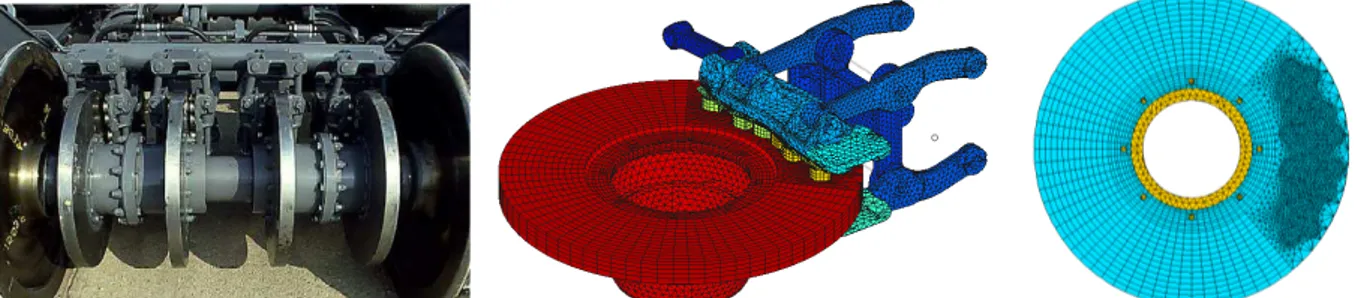
The application proposed in this paper is issued from the AcouFren project driven by the SNCF (French Railway Agency), which aimed at developing tools to assess the link between pad design and brake noise propensity in train brake systems. A simulation software running in the SDT environment (13) capable of performing acoustic emission estimation from pad designs was developed, and used for this paper study. The TGV (French high speed train) brake is considered in this paper as presented in figure 1. Four disc brakes are mounted on each wheel axel through hubs. For each brake, a caliper unit applies the pressure on the disc.
Figure 1: The TGV disc brake system. Left implementation in the train. Middle, high fidelity finite element model. Right, the disc-hub subassembly with remeshed friction track under the pad.
The total brake finite element model presented in figure 1middle weights over 1 million degrees of freedom (DOF). Remeshing of the disc braking track to get a compatible mesh between the disc and pad is performed as illustrated in figure 1right. The disc to hub coupling is realized through 8 bolts that are modelled by linear beam elements and ideal multiple point constraints between contacting surfaces in the radius of the bolt head.
This paper presents the steady-sliding formulation necessary to perform the complex eigenvalue analysis (CEA) and associated convergence control concepts in section 1. The
damping modelling strategy for the disc-hub subassembly using modal damping is then presented in section 2. Section 3 eventually presents the application to the industrial brake, illustrating the sensitivity of stability results to damping.
1. SQUEAL CEA USING SMART SUBSPACE BASED RESOLUTION Formulation of steady sliding instabilities with a rotating disc
The brake system is modelled by finite elements, non-linearities are present at the contact between pad and disc and the disc is rotating at a constant velocity speed Ω. The static deformation of the brake can be obtained for a steady-sliding state. To avoid repetition of intensive contact pairing, small sliding is commonly considered for a disc in a rotating frame. Such formulation thus considers the disc rotation as a material flow in a fixed mesh looking like an Eulerian formulation. To ease up contact formulation, a cylindrical local orientation map is considered (and used in SDT) for pad-disc contact, points allowing the expression of friction forces in the angular and radial directions, as presented in figure 2.
Figure 2: A local cylindrical map for pad-disc contact modelling.
The pad-disc contact friction law is based on the ideal Signorini-Sliding Coulomb law to alleviate contact parameter identification apart from the friction coefficient μ, considered constant. For a contact point one thus considers the following relation between pressure and gap for each contact point ,
0 0
0
(1) The steady sliding assumption states that every closed contact point between the pad and disc is sliding. The friction force is thus expressed as opposed to the sliding velocity with a norm driven by the pressure modulated by the friction coefficient,
(2)
It was shown by the authors in (14) that equivalent static and dynamic properties can be obtained between ideal formulations and calibrated functional (or penalized) formulations. A specific static resolution of the steady sliding state based on contact status iterations,
presented in (14) along with further details on the finite element implementation, was used for this study.
For mode computation, the ideal Signorini contact law linearization induces normal
displacement constraints applied to closed contact points so that no relative interface normal displacement is allowed. This constraint can be put to its canonical form using an observation matrix that provides the gap for each closed contact point,
The linearization of friction forces induces two terms, one linked to the variation of the contact forces and one linked to the variation of the sliding direction,
"# , %&! ' ( ) ! * + ,-./ 0+21 345 67 + %! (4) Observation of tangential displacements in the angular direction ( and in the radial direction + are here used, and one notes 345 the product of the Gauss contact integration point weight and Jacobian.
The first term of equation (4) is non symmetric and couples normal to tangential directions as a variation of the normal displacement will alter the contact pressure thus the friction force norm. However a variation of the tangential displacement will not induce a variation of the friction force in sliding conditions. This term is purely angular as the steady sliding velocity is directed in the disc motion direction.
The second term of equation (4) is symmetric and dampens radial displacements at the pad disc interface. In practice, a variation of the sliding direction decrease friction forces in the angular direction.
One then searches solutions of the form #8&! 9 :; 5 applied to the system linearized in the vicinity of its current steady sliding state. Contact statuses are verified by assuming
9 = 0, that requires a projection of the system the gap observation kernel < .
The contact force reaction is the dynamic response of the structure to its current deformation state, one thus has ) ! = = + ? @ + ?' A < 9 , noting = , @ , A
respectively the elastic underlying linear stiffness, damping and mass matrices. Linearized friction forces can thus be written
"! = − B= C + ? B@ C + ?'BA C + ? B@ +C < 9 (5) noting BD C =' ( D and B@ +C the radial damping term of equation (4).
The system complex modes eventually verify
E < F = + B= C + ? @ + B@ C + B@ +C + ?' A + BA C G < 9 = 0
9 = < 9 (6)
Equation (6) is commonly transformed into a first order equation on the system state that doubles the order. To avoid costly direct complex resolutions one first reduces the system on a basis made of Rayleigh-Ritz vectors. A natural choice is the real mode basis of the
underlying symmetric undamped system verifying
< = − H' A < I = 0 (7)
Defining the reduction basis <J = BI C
1K KL, reduced complex modes will verify
9 = <J 9M (8)
and the final system (6) can be projected,
,B@N C + B@NBAN C +C BAN C0 7 ,BONC PBONC 7 P + ,B=N C0 BAN C0 7 ,BONC PBONC 7 = Q00R (9) noting BDM C = <J < D + BD C < <J the reduced elastic matrices with resolved contact constraints, B@N +C the projection of the radial friction damping term, BONC the reduced complex mode shapes and P the corresponding eigenvalue matrix.
The Residue Iteration method for damped systems
The resolution of equation (9) is commonly resolved using a QR algorithm. Although very stable, convergence may suffer from numerical conditioning. More importantly the initial subspace choice <J may not be fully appropriate for the resolution. Some modes might be missed, and accuracy of eigenvalues can be challenged.
The residue iteration method has been developed by Bobillot et al. (9) and can be compared to pre-conditioned gradient methods. The solution accuracy is evaluated by estimating
residual forces )S J coming from the solution inaccuracy, injecting solution ? , 9M in the non-projected system equation,
< F = + B= C + ? @ + B@ C + B@ +C + ?' A + BA C G < 9 = )S J (10) Residual displacements )T J can then be evaluated by computing the system static response to the residual forces,
)T J = = U1 )S J (11)
so that an error relative to the strain energy norm can be computed,
VJ = WX Y
Z[\] WX Y
^; ^_ (12)
noting that ^? ^' is related to modal strain energy.
Real and imaginary parts of the residual displacements producing an error larger than a given tolerance V can thus be chosen to enhance the current subspace,
<`a1 = <` ℜ#)T`c & ℑ#)T`c & e (13)
An orthonormalization procedure is then used to keep a good conditioning for <`a1 . It is then possible to iterate as long as all eigenvalues are properly converged, or at least to quantify the confidence one has on the result after no or a few iterations.
Based on the residue iteration idea, a priori subspace enhancement can be tried before the first resolution. A first residue can indeed be estimated as proposed in (10) by considering the action of the friction forces over the modal trajectories constituting the initial subspace,
B)T[∗ C = =4g U1B= C < <J (14)
For large systems with close eigenvalues, numerical conditioning may become an issue. In particular finite numerical precision makes bases resulting from the orthonormalization process sensitive to the initial vector ordering.
2. A DAMPING MODEL EXPLOITING (SUB)COMPONENT MODAL PROPERTIES AT THE SYSTEM LEVEL
Understanding experimentally identified damping of sub-assemblies
The disc-hub subassembly of the TGV train presents bolted joints that alter its modal damping ratios. It could be shown in (15) that the external solicitations of a joint coming from the deformation of the system have an effect on the joint dissipation. To avoid complex joint modelling and to integrate damping at a greater scale from experimental identification, it was thus chosen to consider subassembly modal damping.
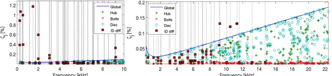
The first modelling approach considered a Rayleigh damping model for the whole frequency band (0-20kHz), based on an optimization of the damping ratios experimentally identified in the 0-15 kHz frequency band. The resulting modal damping ratios are illustrated for the disc-hub in figure 3right as the blue curve Global.
It could however be observed that great discrepancies could occur for specific experimental modes, as some modes where very lightly or highly damped. Modes greatly differing from the nominal Rayleigh damping model are shown in figure 3 as the red markers ID diff.
Figure 3: Disc-hub subassembly modal damping ratios from the Rayleigh damping model, differing experimental damping ratios (vertical dotted lines with markers), and component participation.
To understand differences, component participation to the subassembly damping following the modal strain energy (MSE) assumption has been reported in figure 3. It could be observed that modes with very light damping ratios mainly concerned pure disc modes like presented in figure 4f. Low frequency modes with large damping ratios seem to involve global disc
movements on a rigid hub, figure 4a-b, with displacements prone to large joint dissipation. Modes with mixed participations, e.g. figure 4c-e can induce different effects depending on non-trivial joint solicitation.
a b c
d e f
Figure 4: Sample disc-hub modes with identified damping.
Sub-assembly based damping modelling strategy exploiting test results
The idea in the AcouFren project was to exploit experimentally identified modal damping ratios of the disc-hub subassembly. Refined simulations producing such damping ratios could also be used and could alleviate the test frequency limit problem.
To consider sub-assembly modal damping, the displacement vector of the full brake can be split into DOF relative to the sub-assembly and other DOF h.
! = i hj (15)
One can then expand the sub-assembly real modes identified experimentally on the full brake,
k = lI mn no
0 p (16)
As the disc-hub sub-assembly is disjoint from the rig and only coupled by contact, this basis is normalized regarding the mass norm,
k A k = q (17)
so that a pseudo-inverse of the modal basis can be easily computed,
k a= k A (18)
This allows recovery of the global damping matrix induced by the disc-hub modal damping. Indeed, the sub-assembly modal damping matrix rs is diagonal and results from the projection of the full modal damping matrix in the physical basis @s
rs = k @s k =B-./ 2u H C (19)
Equation (18) allows the inversion of (19),
@s = A k B-./ 2u H C k A (20)
thus providing the sub-assembly modal damping matrix in the full finite-element space. In practice this matrix cannot be computed as it is full and of large size. For a 1 million DOF system it would weight over 7 TB.
The projection of matrix (20) on a real mode subspace would be full but only weight 7MB for a 1,000 mode subspace. Good organization of the matrix expression makes it very affordable,
B@Ns C=# k A < <` & B-./ 2u H C# k A < <` & (21) If the modal damping matrix is used in combination to other contributions like Rayleigh damping for this paper application, the total damping matrix can be noted
@ = @s + @v5w4+ (22)
Its projection on the modes of interest will yield
r = B-./ 2u H C + k @v5w4+ k ≈ B-./ 2u H C + B-./ 2uv5w4+ H C(23)
The modal damping matrix is assumed mainly diagonal so that corrective terms can be applied to the damping ratios separately for each mode, using us yu − uv5w4+ so that the damping ratios resulting from the total damping terms are correct.
3. APPLICATION TO THE INDUSTRIAL TGV DISC BRAKE Convergence pattern of the complex modes
This paper illustration targets system modes in the 0-10kHz frequency band, for which noise measurements were available. For the pad fitted in the example, this resulted in the
computation of 700 complex modes. The initial subspace was found to provide fairly
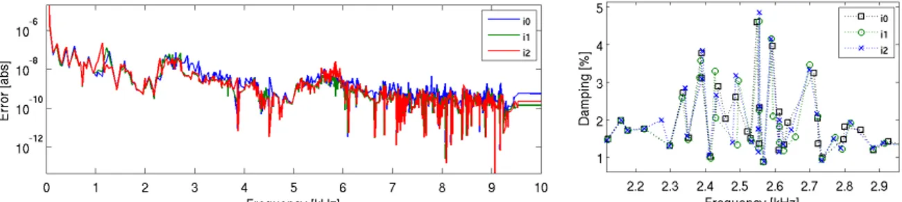
satisfying convergence as the error indicator presented in figure 5 showed that all modes were under an error of 10-6, only 6 shapes were added after two subspace iterations.
It could be seen in practice that the variation of the real part was more sensitive than the variation of the imaginary part, so that a refinement of the error criterion may needed in the
future. Variations in the stability diagram are small, and mainly located in the multiple lining block modes, as illustrated in figure 5right.
Figure 5: TGV brake complex mode convergence pattern. Left, error indicator as function of the residue iterations (2 iterations performed). Right, sample frequency/damping variations during the iterations.
To avoid multiple matrix factorization, the residues of equation (11) have been computed with the shifted stiffness matrix, ensuring better convergence at the end of the frequency band. It could thus be observed that improvement of the error criterion mostly occurred at the end of the frequency band, and that no improvement could be obtained for some lower frequencies. A clear perspective to this work is then to consider multiple shifting strategies with local enhancement to ensure better convergence over the whole frequency band.
System stability as function of the damping models
Three damping strategies for the disc-hub sub-assembly were tested for the project,
considering either no damping at all (DD 0), or only identified Rayleigh damping (DD R), or modal damping combined to Rayleigh damping as presented in section 2 (DD M+R).
Figure 6: TGV brake stability diagram as function of the disc-hub damping model. Left, global view. Right, zoom-in on the unstable modes.
Figure 6left presents the stability diagram resulting from these different strategies. As the brake rig shows higher damping levels and this pad was the most silent pad in the test panel, the overall stability diagram does not vary much as function of the disc-hub damping strategy. Significant variations could however be observed for unstable modes, in figure 6right.
One unstable mode and several close to instability modes could be found for the no damping strategy, no unstable mode was found for the Rayleigh damping strategy and two modes presented in figure 7 could be found for the modal damping strategy. This latter case confirmed occurrence of non-intuitive damping effect, where increasing damping for a sub-assembly added instability to the system.
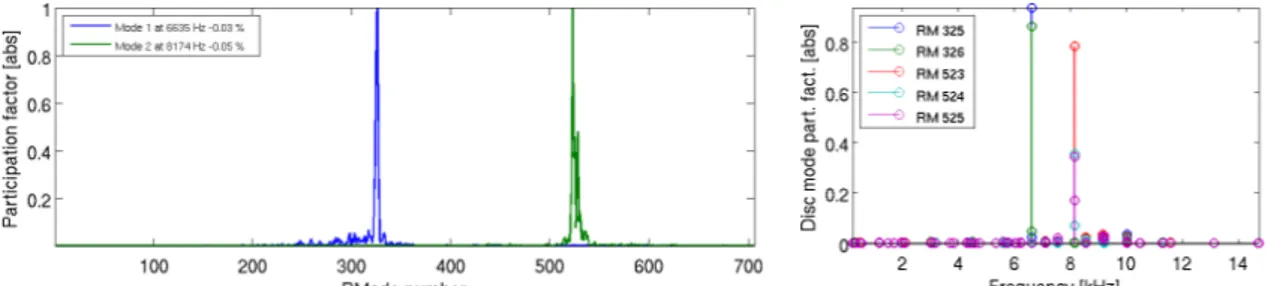
To push forward the analysis, disc-hub modal participation to the found unstable modes was estimated. First the real mode participations to both complex modes was evaluated using a direct projection (resulting from equation (9)). The results presented in figure 8 show that only 2 real modes significantly contribute to the first unstable mode (325 and 326) and 3 for the second one (523, 524 and 525).
Figure 8: Left, projection of the unstable complex modes on the real mode basis. Right, disc-hub modes contribution to the real modes involved in the unstable complex mode expression.
The projection of the real mode shapes onto the disc-hub sub-assembly modes can then be performed, following the concept of equations (18)-(20). Only one couple of lightly damped double disc modes is contributing to each complex mode.
CONCLUSION
Accurate estimation of damping for brake squeal simulation is a critical yet challenging task. System stability obtained through CEA can hit convergence issues and great sensitivity to chosen damping models is common. This paper thus proposed a few techniques to improve control of such simulation.
First, a convergence estimation technique adapted to subspace based resolutions methods was presented. An error indicator was developed to quantify convergence error for each complex mode. It also provides a way of subspace enhancing close to pre-conditioned conjugate gradient methods to improve convergence. Such method opens the way to a priori subspace enhancement techniques. For performance improvement for large frequency bandwidths like seen in brake squeal simulations, the questions of local band enhancement and smarter
enhancement vector selection and ordering for the normalization can be raised. It constitutes a clear perspective of this work.
Second, an improved damping model considering sub-assembly modal damping was
presented. This damping model can be combined to other damping models and allows direct modal damping ratio assignment. These ratios can come from test measurements or from refined sub-assembly simulations, and opens the way to more comprehensive global damping modelling at assembly levels, as presented by Chiello et al. in (16). For example joints induced damping can be accounted for without refined joint modelling or without specific macroscopic joint model identification. In the same manner, damping in composite materials like carbon ceramic discs can also be modelled at the component scale. Complexity at the system level can thus be controlled while improving component behaviour accuracy.
ACKNOWLEDGEMENTS
The authors wish to thank the members of the AcouFren project, SNCF, IFSTTAR-LTE, SDTOOLS, VIBRATEC, ENPC, ECL-LTDS, ALSTOM TRANSPORT, BOMBARDIER, FAIVELEY, and funder ADEME under the convention 0966C0281.
REFERENCES
(1) Akay A., “Acoustics of friction”, The Journal of the Acoustical Society of America, 111(4), 1525-1548, 2002.
(2) Heussaff A., Dubar L., Tison T., Watremez M., Nunes R. F., “A methodology for the modelling of the variability of brake lining surfaces”, Wear, 289, 145-149, 2012. (3) Fieldhouse J. D., Newcomb T. P., “Doubled pulsed holography used to investigate
noisy brakes”, Optics and Lasers in Engineering, 25 (6), 455-494, 1996.
(4) Sinou J. J., “Transient non-linear dynamic analysis of automotive disc brake squeal– On the need to consider both stability and non-linear analysis”, Mechanics Research Communications, 37(1), 96-105, 2010.
(5) Vermot des Roches G., “Frequency and time simulation of squeal instabilities.
Application to the design of industrial automotive brakes”, PhD thesis, Ecole Centrale Paris, CIFRE SDTools, 2010.
(6) Sinou J. J., Loyer A., Chiello O., Mogenier G., Lorang X., Cocheteux F., Bellaj, S.,
“A global strategy based on experiments and simulations for squeal prediction on
industrial railway brakes”, Journal of Sound and Vibration, 332(20), 5068-5085, 2013.
(7) Coudeyras N., Sinou J. J., Nacivet S., “A new treatment for predicting the self-excited vibrations of nonlinear systems with frictional interfaces: The constrained harmonic balance method, with application to disc brake squeal”, Journal of Sound and Vibration, 319(3), 1175-1199, 2009.
(8) Loyer, A., Sinou, J. J., Chiello, O., Lorang, X.,“Study of nonlinear behaviors and modal reductions for friction destabilized systems. Application to an elastic layer”, Journal of Sound and Vibration, 331(5), 1011-1041, 2012.
(9) Bobillot A., Balmes E., “Iterative techniques for eigenvalue solutions of damped structures coupled with fluids”, AIAA-43, 2002.
(10) Brizard, D., Chiello, O., Sinou, J. J., Lorang, X., “Performances of some reduced bases for the stability analysis of a disc/pads system in sliding contact”, Journal of Sound and Vibration, 330(4), 703-720, 2011.
(11) Fritz G., Sinou J.-J., Duffal M., Jezequel L., “Investigation of the relationship between damping and mode coupling patterns in case of brake squeal”, Journal of Sound and Vibration, 307, 591-609, 2008.
(12) Cantone F., Massi F., “A numerical investigation into the squeal instability: Effect of damping”, Mechanical Systems and Signal Processing, 25(5), 1727-1737, 2011. (13) Balmes E., Bianchi J.-P., Vermot des Roches G., “Structural Dynamics Toolbox 6.7
(for use with MATLAB)”, SDTools, Paris, www.sdtools.com, 2014.
(14) Vermot des Roches G., Chiello O., Balmes E., Lorang X., “Benchmarking Signorini and exponential contact laws for an industrial train brake squeal application”, ISMA, Leuven, 2012.
(15) Vermot des Roches G., Balmes E., “Estimation of friction induced modal damping in bolted assemblies through explicit transient simulation”, ISMA, Leuven, 2014. (16) Chiello O., Sinou J. J., Vincent N., Vermot Des Roches G., Cocheteux F., Bellaj S.,
Lorang X., “Squeal noise generated by railway disc brakes: Experiments and stability computations on large industrial models”, In Proceedings of Meetings on Acoustics, 19(1), Acoustical Society of America, 2013.