Science Arts & Métiers (SAM)
is an open access repository that collects the work of Arts et Métiers Institute of
Technology researchers and makes it freely available over the web where possible.
This is an author-deposited version published in:
https://sam.ensam.eu
Handle ID: .
http://hdl.handle.net/10985/14959
To cite this version :
Théo DORLIN, Guillaume FROMENTIN, JeanPhilippe COSTES, Habib KARAOUNI
-Mechanistic cutting force model including the stress state induced by the chip flow contribution for
cylindrical turning on Ti6Al4V alloy with two different nose radii - In: 13th International Conference
on High Speed Machining, France, 2016-10-04 - HSM Proceedings - 2016
Any correspondence concerning this service should be sent to the repository
Administrator :
archiveouverte@ensam.eu
Mechanistic cutting force model including the stress state induced by the chip flow
contribution for cylindrical turning on Ti6Al4V alloy with two different nose radii
T. Dorlin1,2, G. Fromentin1, J-P. Costes1, H. Karaouni2 1
Arts et Metiers, ParisTech, LaBoMaP, rue porte de Paris, Cluny, 71250, France 2
Safran Tech, Research and Technology Center, rue des jeunes bois, Châteufort, 78772, France
Abstract
Force modelling is a major research topic in machining. Several approaches are used to face with the different needs. Mechanistic models appear to be an easier and rapid way for computing cutting forces; nevertheless they may suffer from accuracy and physically meaning. This article is presenting an advanced mechanistic cutting force model for turning on Ti6Al4V alloy. It considers the effect of the chip flow direction on cutting forces. The proposed model is compared to a basic one and demonstrates its ability to predict more accurately the feed force and the penetration force, which are usually difficult to evaluate.
Keywords:
Cutting forces modelling; Chip Flow; Titanium alloy turning.
1 INTRODUCTION
In aeronautic industry, facing higher requirements related to the design of the complex components is usual. Reducing onboard weight induces a lower stiffness and leads to difficulties due to the need of higher precision in machining. Indeed, inappropriate cutting forces lead to part deflection and affect their final dimensions. Furthermore, engine parts are made of low machinability alloys which could generate significant tool wear [1]. Consequently, complex simulation methods are developed to anticipate the dynamic and mechanical behaviours of the tool and the part during machining. The main objective is to ensure the part dimensions and its surface quality. Cutting forces are considered as a major input data in order to simulate machining processes. With considering the profile turning of a turbojet drum, the aim of this study is to propose a mechanistic cutting force model for cylindrical turning of the Ti6Al4V titanium alloy. Force modelling is a widely research area studied for decades [2]. FEM force modelling is appropriate for the understanding of local cutting phenomena. Nonetheless, it induces long computation and cannot be introduced into a dynamic behaviour modelling of the machining system. Consequently, the use of mechanistic force model seems to be more adequate.
Inspired by mechanical description of metal cutting [3], mechanistic approaches for predicting cutting forces were initially defined by Armarego [4], who expressed cutting forces induced by the material shearing as a function of the local uncut chip thickness evolution. Later, this concept was extended by many authors with consideration of other parameters effects [5]. However, as first highlighted by Albrecht [6], several contributors underlined that in some machining cases, especially in finishing operations, modelling only the cutting forces generated by the material shearing isn’t enough to provide a precise cutting force prediction [7]. This gap between cutting force measured and cutting force predicted is supposed to be linked to the contact at the cutting tool-workpiece interface, which is often neglected
in first approximation. Therefore, in the aim of improving the modelling of this contribution, several studies focus on the tool edge radius effect [8], or part radius effect [9] on cutting forces, which are representative elements of cutting tool-workpiece interaction. Campocasso [10] also pointed out that the tool nose radius has an effect on the cutting forces evolutions in turning of pure copper. As finishing operations are performed with a depth of cut close to the tool nose radius value of the cutting tool, cutting force modelling might be optimised by taking into account this parameter.
Consequently, the aim of this study is to propose an advanced mechanistic cutting force model for cylindrical turning on Ti6Al4V titanium alloy. It is considering contour turning tools with two different nose radii. For same cutting conditions, the change of this parameter affects the chip flow direction. However, chip flow is also contributing to cutting forces, as mentioned by several authors [11–13]. Therefore, the approach developed in this study has to consider the cutting conditions locally to the tool edge in order to formulate a meaningful mechanistic model. The study is declined into four main sections. Firstly, experimental details are provided. The second part is devoted to the presentation of the two cutting force models compared in this study. Thirdly, cutting force prediction results are presented and analysed. Finally, based on previous observations, some conclusions are proposed.
2 EXPERIMENTAL DETAILS
All trials are realised in cylindrical turning by using a two-axis CNC lathe. Two uncoated tungsten carbide round inserts, which have no-obliquity, different tool nose radii (2 and 5 mm), but same small nominal rake and flank angles (i.e. equal to 7°), are employed. Cutting trials are performed within the same Ti6Al4V titanium alloy workpiece and over almost the same machined diameter in order to limit dispersions. The cutting forces are gathered using a 9121 Kistler dynamometer and a 5019A Kistler charge amplifier. Analog outputs are also collected
from the numerical command in order to monitor the main cutting parameters (cutting speed and feed rate) and the tool position in the machine frame.
A strategy is developed in order to limit tool wear propagation during experiments and allow comparison between trials. Firstly, each trial is realised under lubrication and within a small cutting length equivalent to five workpiece revolutions. Secondly, cutting trials number is limited as much as possible. However, some trials are repeated in order to evaluate cutting force measurement repeatability. Based on these considerations, an experimental design made of 18 trials is defined. Depth of cut values are respectively set to 30 %, 60 % and 90 % of the tool nose radius value. Feed rate is declined under three values in order to cover a large range of turning operations, from roughing to finishing. Cutting speed is fixed to 90 m/min according to tool-pair method results. Details are provided in Table 1.
Trial r ε f a p Ø m F f F p F c # mm mm/r mm mm N N N 1 5 0.1 4.5 153 552 521 1028 2 5 0.2 4.5 153 723 666 1686 3 5 0.3 4.5 153 991 843 2269 4 5 0.1 3 156 548 635 777 5 5 0.2 3 156 597 716 1224 6 5 0.3 3 156 636 776 1593 7 5 0.1 1.5 159 217 422 412 8 5 0.2 1.5 159 238 482 659 9 5 0.3 1.5 159 246 520 852 10 2 0.1 1.8 149 191 197 408 11 2 0.2 1.8 149 240 243 658 12 2 0.3 1.8 149 330 327 918 13 2 0.1 1.2 151 189 234 303 14 2 0.2 1.2 151 199 261 480 15 2 0.3 1.2 151 214 298 639 16 2 0.1 0.6 152 78 160 163 17 2 0.2 0.6 152 85 188 260 18 2 0.3 0.6 152 93 202 344
Table 1 : Experimental design in cylindrical turning.
3 CUTTING FORCE MODELLING 3.1 Modelling methodology
Figure 1: Edge discretization principle in the case of cylindrical turning with a round insert [14]. As illustrated by Figure 1, the cutting force modelling approach, in this study, is based on the principle of discretizing a complex cutting edge into several simple segments. On each of these segments, local cutting forces are expressed according to a local cutting law depending on parameters (geometrical description and/or cutting parameters) and constants. Then, these local cutting forces are integrated (projection and sum) all along the cutting edge to compute global cutting forces.
This methodology has the advantage to be adaptable to all cutting tools geometries. Only constant values of the local cutting law have to be calibrated in order to be representative of the cutting tool edge-machined material pair used when machining.
3.2 Armarego’s mechanistic model
In order to model global cutting forces, a local cutting law has to be defined. A commonly-used local cutting law has been defined by Armarego [4], and given by Eq. (1). This local cutting law depends on an affine function of the uncut chip thickness. The description of the uncut chip thickness evolution along the cutting edge is detailed by Campocasso [15]. The “cut” effect corresponds to the contributions on cutting forces of the material shearing and the interaction between the rake face of the cutting tool and the chip, while the “edge” effect is representative of the cutting forces generated by the interaction between the clearance face of the cutting tool and the generated surface. Furthermore, this formulation assumes that each segment is independent from others. Physically, this hypothesis means that on each segment, the chip flows in the direction of the normal to the considered segment. Based on these assumptions, the resulting force can be projected in two local force components, and then global cutting forces are determined as mentioned in Eq. (2).
edge effect cut effect
i, j e,i c,i j
f = k
+
k
× h
(1)
seg seg seg c v, j f h, j j N s b j =0 Nb j =0 Nb j =0 p v, j j F = f F = f with ° F × b × sin(θ )× b λ = 0 × sin(θ = f )× b (2)with i {v; h} = force components and j = segment index. 3.3 Advanced mechanistic model including chip flow
contribution to cutting forces
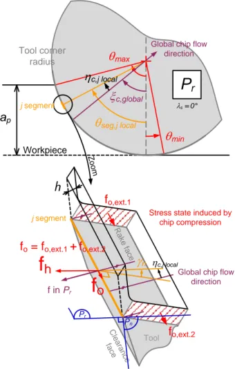
However, the hypothesis of independence between discretised cutting edge segments is discussed by several authors. Indeed, this hypothesis may be true when considering a cutting edge having a low curvature, like in flank milling with a cylindrical mill, but in turning within the nose radius it may be a coarse approximation. Consequently, based on contributions from Kapoor, Molinari and Moufki [11–13], it has been observed that the local force model can be enhanced considering a third local force component. This component represents the contribution of the stress state induced by the chip flow to cutting force. Contrary to Armarego’s suggestions, as illustrated in Figure 2, it assumes that the chip flows into a global direction, defined by the ξc,global angle. Then, this
direction may be different from the local orientation of each edge segment, noted as the θseg, j local angle. When
these two angles are not equals (i.e. ηc, jlocal 0 ), it
appears a resultant force from the two sides of the elementary chip in order to orientate the chip flow in a given direction instead of following the direction of the normal to the considered segment. Molinari and Moufki [12] defined this contribution in a direction which has a projection in every direction of the {fv; fh; fo} frame. In this
study, the choice is made to only consider the main projection in the fo component direction.
Circular edge Active edge min
max
h
r mX
Y
m mZ
Active segmentsh
o
v
Global forcesb
pF
F
c fF
Local forces vf
hf
of
Figure 2: Geometrical model for chip flow direction and third local force component [9].
As a consequence, the formulation of the third component
fo on the edge segment is resulting from Eq. (3) and
Eq. (4), where Eq. (4) is an approximation of a more complex model proposed by Molinari and Moufki [12]. Nevertheless, fv and fh components are unchanged and
still given by Eq. (1).
c, jlocal= c,global seg, jlocal
η ξ - θ (3)
o, j= k ×o,1 ηc, jlocal× hj
f (4)
Moreover, as mentioned by Dorlin [9], in the case of a single tool nose radius value, Moufki and Molinari [13] suggest that for a depth of cut value inferior to the tool nose radius, the global flow direction can be modelled with an affine function of the depth of cut. However, the global chip flow direction seems also to be dependent on the tool nose radius value of the cutting tool. Indeed, for a same cut area (i.e. depth of cut and feed per revolution values), two cutting tools with different tool nose radii will not present the same global chip flow direction due to the different curvatures of each cutting tool. These different curvatures may have an influence on the stress state induced by chip compression. Based on these observations, the global chip flow angle ξc,global is
proposed to be expressed by Eq. (5):
p
c,global o,2 o,3
ε
ξ = k + k ×a
r
(6)
Finally, according to geometrical model detailed in Figure 1 and Figure 2, the fo local force component affects only
the feed and penetration global force on the cutting tool. Consequently, Eq. (2) are modified to become Eq. (7).
s seg seg f h, j j o, j j p Nb j =0 Nb j = v, j j o, j j 0 withλ =0° × sin(θ )× b - f × sin(θ × sin(θ )× b + f × cos( F = f ) F = f θ ) (7)4 CUTTING FORCE PREDICTION RESULTS AND ANALYSIS
In order to identify the constants of each local cutting law (cutting forces and chip flow models), an inverse identification method is used [9]. An algorithm for cutting force calculation in turning has been developed. Then, constants values are determined thanks to an optimization process, which is based on the minimization of the square errors sum between cutting force modelled and measured, and the Levenberg-Marquardt method. The segment length for discretizing the cutting edge is fixed to 0.02 mm, thanks to an analysis of this parameter’s effect, in order to ensure low computation time and robust results. Therefore the number of segments used for discretizing the cutting edge is depending on cutting parameters.
4.1 Armarego’s mechanistic model results
The results from the Amarego’s mechanistic model defined by Eq. (1) are presented in Table 2 and Figure 3. The identification trials used are those presented in Table 1. Despite of the fact that the optimization process is based on a purely mathematical resolution, the first observation is that constants of the local cutting law have values in accordance with their physical meaning. Cutting forces are increasing when the uncut chip thickness grows and they are positive for a zero uncut chip thickness level, which is representative of the ploughing phenomenon. Due to a large number of trials (i.e. number of equations), in comparison with the number of unknowns in the local cutting law, the residual degree of freedom is large. Therefore, it is possible to use the trials used for identifying the model as validation trials. Based on these trials, relative errors of modelling for each global force component are calculated in absolute value and presented in Figure 3. Maximum and Average values of these errors are also mentioned in Table 2.
Model
component
f
hf
vEdge eff. coeff. ke,h= 98 (N/mm) ke,v= 54 (N/mm)
Cut eff. coeff. kc,h= 418
(N/mm²) c,v = k 1377 (N/mm²) Nb.unknowns 2 2 Nb. equations 36 18 Residual DOF. 34 16 Cutting force
F
fF
pF
cMax. rel. err. in
abs. value 31% 23% 6% Ave. rel. err. in
abs. value 12% 8% 3%
Table 2: Inverse identification results with Armarego’s mechanistic model Eq. (1).
The first observation is that the modelling precision of the cutting force Fc is good. The average relative error of
modelling in absolute value is about 3 %, when the maximal relative error of modelling in absolute value is about 6 %. Nevertheless, the second observation
a
p
max
min
seg,j localGlobal chip flow direction
x
c,globalh
c,j localWorkpiece
j segment
Global chip flow direction
P
rf
o
R a ke fa ceh
Stress state induced by chip compression
fo,ext.1
fo,ext.2
f
h
Tool C lea ran ce fa ce Pr hc,j localg
n Tool corner radius f in Pr Pn Z oo m j segmentfo = fo,ext.1 + fo,ext.2
s= 0°underlines that the two others components are not predicted with such accuracy. For the Fp and Ff
components, the average relative errors of modelling in absolute value are respectively of 8 % and 12 %, while the maximal relative errors of modelling in absolute values are about 23 % and 31 %. It has to be noted that the maximal relative error of modelling for the Ff
component is mainly dependent on the fourth trial which presents a huge error of modelling. Without considering this particular trial, the maximal relative error of modelling in absolute value is reduced to 23 %.
Figure 3: Distribution of relative errors of modelling in absolute values obtained with Armarego’s mechanistic
model Eq. (1).
4.2 Advanced mechanistic model including chip flow contribution to cutting forces results
The results obtained from the identification of the advanced mechanistic model are detailed in Table 3 and Figure 4. Once again, the first observation highlights that the constants of the identified model show values in accordance with their physical meaning. Cutting forces are increasing when the uncut chip thickness grows and they are positive for a zero uncut chip thickness level, which is representative of the ploughing phenomenon. Secondly, even if the number of unknown parameters has slightly increased due to the third local force component, for the same reasons as explained in section 4.1, identification trials and validation trials are identic and still detailed in Table 1. As validation trials are the same that those used earlier, it also permits the direct comparison of the predictions realised with the advanced model and the commonly-used model in order to evaluate the value added provided by modelling the chip flow contribution to cutting forces. Based on these trials, relative errors of modelling in absolute values for each component are calculated and presented in Figure 4. Maximum and Average values of these errors are also mentioned in Table 3. Model component
f
hf
of
v Edge effect coefficents e,h k = 95 (N/mm) o,1 k = -36 (N/mm) 2 o,2= 26.10 k (rad) 2 o,3= 73.10 k (rad) e,v k = 54 (N/mm) Cut effect coefficients c,h k = 605 (N/mm²) c,v = k 1377 (N/mm²) Number of unknowns 5 2 Number of equations 36 18 Residual DOF. 31 16 Cutting forceF
fF
pF
cMax. rel. err.
in abs. value 27% 19% 6% Ave. rel. err.
in abs. value 9% 7% 3% Table 3: Inverse identification results with advanced
mechanistic model Eq. (1) and Eq. (4).
Figure 4: Distribution of relative errors of modelling in absolute values obtained with advanced mechanistic
model Eq. (1) and Eq. (4).
Firstly, compared to the results obtained with the Amarego’s mechanistic model, the modelling of the Fc cutting force is unchanged, which is normal because the third local force component does not affect it. However, the advanced mechanistic model improves the prediction of the feed and penetration forces Ff and Fp. Indeed, the
average relative errors of modelling in absolute values are slightly reduced, respectively of 3 % and 1 %, while the maximum relative errors of modelling in absolute values are decreasing of 4 %. These relative errors reductions are greater when excluding the fourth trial, which is presenting significant relative errors of modelling for each global cutting force component with both models. This improvement in cutting force modelling is even more interesting for two reasons. In the first place, reducing maximal relative errors of modelling for Ff and Fp
component is crucial because they are directly involved in
4 516 12 8 11 7 13 15 14 2 18 3 10 6 1 9 17 4 5 1011 13 7 6 8 3 16 14 12 1 917 182 15 10 11 4 1 5 18 2 1312 6 16 15 7 8 173 9 14 0% 5% 10% 15% 20% 25% 30% 35% Re la tiv e e rr or in a bsolut e v a lue (% ) Fc Ff Fp 4 516 12 8 11 7 13 15 14 2 18 3 10 6 1 9 17 4 13 10 5 9 7 11 1 12 2 17 3 14 18 6 15 816 4 1 13 18 10 5 14 12 2 9 11 15 6 7 17 16 3 8 0% 5% 10% 15% 20% 25% 30% 35% Re la tiv e e rr or in a bsolut e v a lue (% ) Fc Ff Fp
part deflections. In the second place, the formulation of the third local force component doesn’t need a new cinematic or geometric local parameter description than those already used in the Amarego’s mechanistic model. In conclusion, based on this comparison, the modelling of the chip flow contribution to cutting forces has a significant effect on the prediction of the Ff and Fp global
cutting force components.
4.3 Advanced mechanistic model results analysis
The formulation of the advanced mechanistic model being quite complex, it is presented an analysis in order to evaluate the physical meaning of this model and the contribution of each parameter in the global modeled forces.
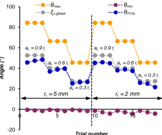
Firstly, the Figure 5 represents the evolution of the chip flow global direction with respect to the trials performed in this study. The first observation is that the identified global chip flow direction values are always contained in the [θ ; min θmax] angular interval. This observation means
that the identified chip flow global direction is always included in the chip area angular range, regardless of the cutting parameters and the tool nose radius associated to each trial. Physically, these chip flow conditions seem to be coherent with the conditions observed experimentally during trials. Furthermore, to keep analyzing the physical meaning of such values, the identified chip flow global direction is compared to the angular position of the {Ff; Fp} resulting global force seen in the tool reference plan,
which might be a relevant indicator of the real chip flow global direction. It appears that both directions are nearly the same for every trial of the experimental design. Nonetheless, contrary to the formulation proposed in Eq. (3), it seems that the feed rate has a slight influence on the angular position of the {Ff; Fp} resulting global
force. Therefore, this effect may have to be analysed more precisely and included in further modelling. Finally, these observations confirm the physical meaning of the identified chip flow global direction.
Figure 5: Identified chip flow global direction evolution and comparison to the angle of the resulting global force
projected in the (Ff, Fp) plane.
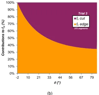
The physical meaning of the identified third local force component can also be analysed for each trial. Figure 6 represents the fh and fo force ratios contributions to the
global cutting forces Ff et Fp with respect to the
orientation of the considered segment for the third trial, which proposes little errors of modelling with both models. It proves that the identified coefficients confirm the
hypothesis made during the description of chip flow effect on cutting forces made in section 3.3. Indeed, Figure 6 highlights the appearance of the third local force only when the local orientation of the considered segment does not match with the global chip flow direction. The contribution of the fo local force component is up to 51 %,
this means that at some points the contribution of the chip stress state to cutting forces can be larger than the ploughing effect contribution.
Figure 6: fh and fo contributions force ratios to Ff and Fp
global cutting forces for Trial #3.
Finally, the local contributions of the “cut” and “edge” effects to fv and fh local force components are also
analysed for this trial in order to determinate which part of the cutting force modelling has to be improved in further research work.
First observation is devoted to the fact that the “cut” effect is the main contributor to the fv component. This is in
accordance with the hypothesis that, for a small rake angle like the one used in this study, this component is mainly representative of the primary and secondary shear zones contributions to cutting forces. However, it is interesting to observe that the main contribution to the fh
local force component is related to the “edge” effect, even for a trial for a large depth of cut, like in the case of the trial illustrated here. Therefore, as the fh local force
component is directly linked to Ff and Fp global cutting
force components, future research works have to focus on the “edge” effect in order to keep reducing modelling errors. (a) -20 0 20 40 60 80 100 0 5 10 15 An g le ( ) Trial number qmax qmin
Ec,global DEGc,global Ff,Fp DEG
ξmax θ Ff,Fp θmin θ ε r = 5 mm r = 2 mmε p ε a = 0.9 r p ε a = 0.6 r p ε a = 0.3 r p ε a = 0.9 r p ε a = 0.6 r p ε a = 0.3 r 0% 10% 20% 30% 40% 50% 60% 70% 80% 90% 100% -2 10 21 33 44 56 67 79 fv and fh fo rce r atio s (% ) ( ) Trial 3 fo ratio fh ratio c,global ξ 52° o f ratio h f ratio 375 segments 0% 10% 20% 30% 40% 50% 60% 70% 80% 90% 100% -2 10 21 33 44 56 67 79 Co n tr ibu tion s to fv (% ) ( ) Trial 3 fv cut fv edge v f cut v f edge 375 segments
(b)
Figure 7: “Cut” and “edge” effects contribution ratios to (a) fv local force component; (b) fh local force component
for Trial #3.
5 CONCLUSIONS
This study is focused on cutting force modelling for turning on Ti6Al4V alloy and based on a mechanistic approach. The main goal was to improve the prediction of the feed and penetration forces, which is a major challenge in order to anticipate the part deflection during machining.
The advanced model proposed is considering the dependence between edge segments and related to the contribution of the chip flow global direction to cutting forces. This contribution modelling is performed considering the appearing of a third local force component in the edge direction. Furthermore, this research work is declined using two different tool nose radii which can lead to different chip flow directions for a same depth of cut, and then act upon cutting forces. The results proposed by this advanced mechanistic cutting force model present relative errors of modelling reduced. Moreover, an analysis is conducted to evaluate: - the physical interpretation of the identified coefficients of the chip flow global direction provided by the advanced mechanistic model;
- the contribution of the “cut” and “edge” effects to local cutting forces in order to determine where future improvements in modelling have to be conducted; - the contribution of local force components to global cutting forces to validate modelling hypothesis.
Future works would have to consider different cutting geometry (tool edge radii, etc.), in order to achieve a more generalised force model. Furthermore, it is a challenge to apply this modeling approach for complex turning tool path.
6 ACKNOWLEDGMENTS
The authors would like to greatly thank the colleagues who also contributed to this present work: Mathias SEVE, Vincent DESSOLY from SAFRAN Aircraft Engines company, and Quentin SUEL, MSc student at Arts et Metiers ParisTech.
7 REFERENCES
[1] E. O. Ezugwu, J. Bonney, Y. Yamane, 2003, An overview of the machinability of aeroengine alloys, J. Mater. Process. Technol., 134/2:233–253.
[2] P. J. Arrazola, T. Özel, D. Umbrello, M. Davies, I. S. Jawahir, 2013, Recent advances in modelling of metal machining processes, CIRP Ann. - Manuf. Technol., 62/2:695–718.
[3] M. E. Merchant, 1945, Mechanics of the Metal Cutting Process. I. Orthogonal Cutting and a Type 2 Chip, J. Appl. Phys., 16/5:267–275.
[4] E. J. A. Armarego, C. J. Epp, 1970, An investigation of zero helix peripheral up-milling, Int. J. Mach. Tool Des. Res., 10/2:273–291.
[5] R. G. Reddy, S. G. Kapoor, R. E. DeVor, 2000, A mechanistic force model for contour turning, Trans. Am. Soc. Mech. Eng., 122/1:398–405.
[6] P. Albrecht, 1960, New Developments in the Theory of the Metal-Cutting Process. Part I: The Ploughing Process in Metal Cutting, Trans. Am. Soc. Mech. Eng., 82/1:348–358.
[7] Y. Huang, S. Y. Liang, 2003, Force modelling in shallow cuts with large negative rake angle and large nose radius tools - application to hard turning, Int. J. Adv. Manuf. Technol., 22:626–632.
[8] C.-F. Wyen, K. Wegener, 2010, Influence of cutting edge radius on cutting forces in machining titanium, CIRP Ann. - Manuf. Technol., 59/1:93–96.
[9] T. Dorlin, G. Fromentin, J.-P. Costes, 2016, Generalised cutting force model including contact radius effect for turning operations on Ti6Al4V titanium alloy, Int. J. Adv. Manuf. Technol., :1–17. [10] S. Campocasso, G. Poulachon, J.-P. Costes, S.
Bissey-Breton, 2014, An innovative experimental study of corner radius effect on cutting forces, CIRP Ann. - Manuf. Technol., 63/1:121–124.
[11] S. G. Kapoor, R. E. DeVor, R. Zhu, R. Gajjela, G. Parakkal, D. Smithey, 1998, Development of Mechanistic Models for the Prediction of Machining Performance: Model Building Methodology, Mach. Sci. Technol., 2/2:213–238.
[12] A. Molinari, A. Moufki, 2005, A new thermomechanical model of cutting applied to turning operations. Part I. Theory, Int. J. Mach. Tools Manuf., 45/2:166–180.
[13] A. Moufki, A. Molinari, 2005, A new thermomechanical model of cutting applied to turning operations. Part II. Parametric study, Int. J. Mach. Tools Manuf., 45/2:181–193.
[14] S. Campocasso, G. Poulachon, J.-P. Costes, S. Bissey-Breton, An innovative experimental study of corner radius effect on cutting forces, CIRP Ann. - Manuf. Technol.
[15] S. Campocasso, J.-P. Costes, G. Fromentin, S. Bissey-Breton, G. Poulachon, 2015, A generalised geometrical model of turning operations for cutting force modelling using edge discretisation, Appl. Math. Model., 39/21:6612–6630. 0% 10% 20% 30% 40% 50% 60% 70% 80% 90% 100% -2 10 21 33 44 56 67 79 Co n tr ibu tion s to fh (% ) ( ) Trial 3 fh cut fh edge h f cut h f edge 375 segments
![Figure 1: Edge discretization principle in the case of cylindrical turning with a round insert [14]](https://thumb-eu.123doks.com/thumbv2/123doknet/7347071.212719/3.892.511.791.490.671/figure-edge-discretization-principle-cylindrical-turning-round-insert.webp)