Science Arts & Métiers (SAM)
is an open access repository that collects the work of Arts et Métiers Institute of
Technology researchers and makes it freely available over the web where possible.
This is an author-deposited version published in:
https://sam.ensam.eu
Handle ID: .
http://hdl.handle.net/10985/19676
To cite this version :
R. BAHI, Corinne NOUVEAU, N.E. BELIARDOUH, C.E. RAMOUL, S. MEDDAH, O. GHELLOUDJ
- Surface performances of Ti-6Al-4V substrates coated PVD multilayered films in biological
environments - Surface and Coatings Technology - Vol. 385, p.125412 - 2020
Any correspondence concerning this service should be sent to the repository
Administrator :
[email protected]
Surface performances of Ti-6Al-4V substrates coated PVD multilayered
films
in biological environments
R. Bahi
a, C. Nouveau
b, N.E. Beliardouh
a,⁎, C.E. Ramoul
a,c, S. Meddah
c, O. Ghelloudj
c aLaboratoire d'Ingénierie des Surfaces (LIS), Université BADJI Mokhtar (UBMA), BP 12, 23000 Annaba, AlgeriabArts et Métiers, Institute of Technology, LaBoMaP, HESAM Université, Rue Porte de Paris, F-71250 Cluny, France cResearch Center in Industrial Technologies CRTI, P.O. Box 64, Cheraga, 16014 Algiers, Algeria
A R T I C L E I N F O Keywords: PVD-coatings Oxides Nitrides Biomaterials Tribology Corrosion A B S T R A C T
Multilayered and nanostructured coatings of Ti based alloys (oxides and nitrides) are elaborated and tested for increasing protective properties such as corrosion and wear resistances. A pin-on-disc tribometer was used to evaluate the wear resistance in Hank's solution against bovine bone. Corrosion behavior in Hank's solution was determined by potentiodynamic and electrochemical impedance spectroscopy techniques. Besides, the specimen surfaces were characterized by Atomic Force Microscopy (AFM), Scanning Electron Microscopy (SEM) and Energy Dispersive Spectroscopy (EDS) microanalyses. The results showed that optimal tribological properties were obtained in the case of coatings having TiN as top layer. The main wear mechanism was abrasive third body wear. In vitro corrosion tests at 37 °C showed that the better corrosion resistance was obtained when TiN was the top layer. However all of them exhibited good tribological properties, good corrosion resistance and then may be promising options for biomedical applications.
1. Introduction
The challenge in biomedical implants is to improve mechanical properties and corrosion resistance as well as biocompatibility at low cost. Ti-6Al-4V alloy is one of the most common materials used as or-thopedic implants into the human body. It has good mechanical prop-erties and favorable biocompatibility in addition to an excellent re-sistance against wear and corrosion in aggressive environments [1,2]. However, it was indicated that Aluminum and Vanadium had a nega-tive biological responses because of their toxicity effects caused by the dissolution of Al and V ions in the human body [3,4]. On another hand, poor tribological behavior of Ti-6Al-4V alloy leads to afine wear debris causing allergy and inflammation. Another disadvantage is that caused by the high difference between elastic moduli of the antagonists in contact i.e. implant and bone; E (Ti-6Al-4V) is around 114 GPa [5], while E (bone) is nearly 30 GPa [6]. Consequently, inconveniences mentioned above lead to a decrease in the service life of the prosthesis [7,8].
To enhance mechanical properties, biocompatibility, osseointegra-tion, wear and corrosion resistance, protecting the Ti-6Al-4V substrates by PVD layers was proven to be a promising solution. TiN and TiO2are
among coatings used as protective because of their non-toxicity, good stability, ease of mass production and high controllability [9,10]. Since
the last two decades, many researchers have shown that multilayer coatings, especially metal/ceramic sequences, improve the mechanical properties of the coating and their resistance to higher corrosion com-pared to monolayer coatings [11–15]. Several interlayers should be deposited on the substrate and below external coating surface. It's found that ductile titanium in the intermediate layers in coatings can reduce internal stresses and improve toughness of hard coatings [16]. The surface of titanium alloy is naturally covered by a passive layer of ti-tanium dioxide (TiO2), when in contact with biological environments.
Thus, passive layer create an interface between the surrounding tissue and the implant promoting osseointegration [17–19].
In the present work, new design of multilayer coatings was elabo-rated by DC magnetron sputtering and evaluated for their suitability as protective coatings for biomedical implants. The tribological behavior (against bone) and corrosion behavior in Hank's solution of the (Ti/ TiN)9and (Ti/TiN)9/TiO2systems have been analyzed and compared.
Multilayer coatings, used in this study, alternating successively hard phase/ductile phase are a biomimetic design inspired from nature (nacre-inspired materials and coatings [20,21]). Hank's solution is the most widely used simulated human bodyfluid, in corrosion tests as an aggressive medium and in wear tests as a bio-lubricant. Wang et al. [22] reported that bio-lubricants should be considered to be an important factor on the tribological behavior of bone and titanium alloys. The
⁎Corresponding author.
E-mail addresses:[email protected],[email protected](N.E. Beliardouh).
extreme conditions of tests, used in this study, are far from being the case in vivo, however accidents may result and they could be an ef-fective tool when choosing the appropriate material for the specific implant.
2. Materials and methods 2.1. Coatings deposition
Coatings were elaborated by reactive DC magnetron sputtering (KENOSISTEC KV40 system), using a high-purity Ti target (99.95%). Ti-6Al-4V substrates were intended for tribological and corrosion tests (Ø = 20 mm × 5 mm, Ra= 165 ± 5 nm) and Silicon (100) wafer
substrates (10 mm × 10 mm × 0.38 mm, Ra= 1 nm) were used for
nondestructive analysis. Coating specimens deposited on Si substrates were cut longitudinally with a diamond tip before SEM observation of the cross section. The Ti-6Al-4V and Si (100) substrates were ex-situ ultrasonically cleaned for 10 min in acetone and deionized water suc-cessively.Fig. 1shows a scheme of the multilayer coatings elaborated in the present work. The design consists of a pure Ti metal under layer (~100 nm) for all the samples. Afterwards, alternating (Ti/TiN) layers were performed by controlling the reactive nitrogen flow (purity: 99.999%). Specimens“type C1” are composed of substrate + nine re-peating Ti/TiN layers (~180 nm thick); which means a total of eighteen (18) layers. Specimens“type C2” and “type C3” were elaborated firstly as well as C1. Then, the nitrogenflow was stopped and oxygen (purity: 99.995%) was introduced into the chamber. The process was conducted with a continuous gasflow (mixing Ar + O2) ensured by an MKS
mass-flow controller during 720 s. The pressure was kept constant at the level of 0.5 Pa. The focus is to form a TiO2film as a top layer (~200 nm).
Two O2partial pressures are employed i.e. O2/Ar ratio = 0.12 and O2/
Ar ratio = 0.26 during the elaboration of C2 and C3 specimens re-spectively. The deposition parameters are summarized inTable 1.
2.2. Characterizations 2.2.1. Coating adhesion
Coating adhesion was evaluated by scratch test. The lower critical load LC1(cohesive failure) and the critical load LC2(adhesive failure)
were measured with a CSM Instruments scratch tester equipped with a diamond stylus (Rockwell C, 200 μm radius tip) under progressive loading conditions of 1–50 N, with a 5 mm scratch length. All speci-mens are tested in the same conditions (Table 2).
2.2.2. Corrosion
Electrochemical investigations were carried out with Autolab po-tentiostat/galvanostat in 100 ml of the Hanks' solution at 37 °C (pH = 7, and composition in (g/l): 8.0 NaCl, 0.4 KCl, 0.2 MgSO4·7H2O,
0.16 CaCl2·H2O, 0.04 Na2HPO4, 0.06 KH2PO4, 0.35 NaHCO3, and 1.0
Glucose). The temperature of the electrolyte was controlled by ther-mostat with water recirculation at 37 ± 1 °C. Global measurements were performed using a classical three-electrode cell; Pt and Ag/AgCl (3M KCl solution) are employed as counter and reference electrodes, respectively. The electrochemical impedance spectroscopy (EIS), was performed at open circuit potential (OCP) after a time period of 1 h. The frequency range was from 105kHz to 10−2Hz at a rate of 5 points/
decade in Eocpvs Ag/AgCl and the amplitude was set at 10 mV. The
potentiodynamic polarization test was raised from−1 V to +1 V, at a scan rate of 1 mV/s. Before the test, specimens were immersed in the electrolyte for 2 h to attain stable open circuit potential (OCP). The polarization resistance (Rp) was estimated from Tafel curves using
Stern–Geary equation as follows:
= × + × R β β a βc I 2.3039(β ) 1 p a c corr (1)
whereβa,βcare the slopes of anodic and cathodic Tafel plots.
2.2.3. Tribology
Bovine cortical bone was designed to be the upper friction coun-terpart against rotating Ti-6Al-4V, C1, C2, and C3 disc specimens to further simulate their (bone) in vivo tribological behavior. As this is not possible to have spherical ball from organic matter of animal origin (cartilage, bone, etc.), the pin-on-disc configuration provided by ©CSM Instruments (Switzerland) tribometer is perfectly adapted for this case and is described in details in a previous work [23]. The bone pins were prepared (cylinder Ø = 6 mm × 20 mm, Ra = 0.73μm) from a bovine femur. Wear tests were conducted in accordance to the ASTMG99-95a to determine the coefficient of friction (COF). The geometry of the pin-on-disc tests is shown inFig. 2. During the tests, discs were completely immerged in Hank's solution. Theflowing parameters were kept con-stant: applied load (N = 3 N), sliding speed (v = 5 cm/s) and track radius (r = 4 mm). The sliding distance of 100 m was long enough to produce a breakdown of the coating. The specific wear rate was ob-tained by the classical formula as follows:
=
W V
NL(mm /Nm)
s 3
(2) where Wsis the specific wear rate, V is the wear volume [mm3], N is the
normal load [N] and L is the sliding distance [m]. The Wsestimation
was automatically obtained by short software [23] using 3D
Fig. 1. Scheme of the studied multilayered coatings on Ti-6Al-4V substrates.
Table 1
Deposition parameters.
Gas mixture Coatings
Ti TiN TiO2
Arflow (sccm) 95 68.8 90
N2flow (sccm) – 33.3 –
O2flow (sccm) – – (C2 = 11), (C2 = 24) Target-substrate distance 120 mm
Substrate bias voltage −350 V Residual pressure (Pa) 2.10−5 Working pressure (Pa) 0.5
Table 2
Thickness, adhesion and chemical composition of the layers.
Samples Thickness (μm) Adhesion test Contents (at.%) LC1(N) LC2(N) N O Ti
C1 1.6 9.02 ± 1.5 30.16 ± 0.6 4.2 6.3 89.5 C2 2.6 9.27 ± 0.7 32.24 ± 0.5 0 13.5 86.5 C3 2.0 9.5 ± 0.5 32.5 ± 0.5 0 27.9 72.2
profilometry image (Optical profilometer VEECO, Wyko NT-1100). The surface morphologies of discs and pins were examined by SEM/EDS (JEOL JSM-5900-LV microscope).
2.2.4. Surface roughness and structure
The roughness of coatings on Ti-6Al-4V substrates was determined using a 3D profilometer while roughness of the coatings on Si (100) substrates was obtained by using an atomic force microscope (AFM, Explorer, VEECO Topometrix). The scanning area of each image was set at 5μm × 5 μm with a scanning rate of 1.0 Hz to obtain a detailed surface image. The structure of the coatings was analyzed by X-ray Diffraction (Bruker diffractometer; radiation source (λ) Co(Kα)= 0.1789 Å). The diffraction scanning angle ranges from 20 to
80° at a scanning rate of 1°/min. 3. Results and discussion 3.1. Microstructural characterization
Prior to any microstructural analysis, the microstructural phases must be identified. XRD analyses were carried out by using the con-ventional symmetrical Bragg-Brentano configuration on C1, C2 and C3 samples to determine the structure of the top layer on the specimen.
Fig. 3shows the XRD patterns that highlight the crystallinity of the deposited films on Si (100) substrates. It shows, for C1 C2 and C3 specimens, typical diffraction peaks of TiN phase ((111) at 2ϴ = 41.313° and (200) at 2ϴ = 47.16°), Ti (200) at 2ϴ = 44.96° and
TiO2anatase phase ((112) at 2ϴ = 54.65°, (211) at 2ϴ = 56.45°, (220)
at 2ϴ = 62.68°, (221) at 2ϴ = 65.95°, and (113) at 2ϴ = 72.94°) according to the standard ICDD cards N° 01-074-1214, 00-044-1294 and 01-071-1169 respectively and compared with available literature [10,16]. Peaks at 2ϴ = 38.63° and 73.413° are related to the substrate
i.e. Si (200) and Si (400) respectively (ICDD card N° 00-027-1402). Our findings provide a unique anatase phase for the two oxygen flow. It was suggested that the selective crystal phase of TiO2 thin films (rutile,
anatase) is based on the oxygen concentration during reactive magne-tron sputtering [24].
Remark: the strongest picks related to Si substrate (2θ > 80°) were voluntary removed from XRD patterns.
Fig. 4 shows the cross sections and surface morphology of the multilayerfilms. One can observe that the coatings fully cover the Ti-6Al-4V substrates.Fig. 4(a–c) depicts the cross-section SEM images of
C1, C2 and C3, respectively. It is shown the typical columnar structure of PVD coatings i.e. vertically aligned nanocolumns; the largest hor-izontal section, are between 70 and 120 nm. The sequence (horhor-izontal) of the alternating layers appears clearly; the sharp boundaries are seen at the different interfaces; it is then possible to count directly the al-ternated layers of TiN and to estimate approximately the size of the nanocrystallites. The SEM images inFig. 4(d–f) show that TiN (Fig. 4d) presents a different surface morphology in comparison to the TiO2one
(Fig. 4(e–f)). Moreover, “protuberances” and micropores are observed
at both TiN and TiO2surfaces. A fine microstructure constituted by
small grains with narrow size distribution was shown in the case of TiN films. Surfaces of TiO2 films show almost spherical agglomerates of
columns. They also present a compact and homogeneous surface mor-phology but some irregularities such as pores are clearly seen. The composition of the surface layers was analyzed by EDS microanalyses. The total thickness of the coatings and thefinal chemical compositions are listed inTable 2.
Fig. 5shows the three dimensional AFM images of TiN (C1) and TiO2(C2 and C3) coatings surface. It is obvious that all thefilms have a
compact structure with several “keen peaks” i.e. column tops. The roughness of these thin films was characterized according to Ra
(Roughness average) and Rq(Rq= Root Mean Square). As presented in
Fig. 5, the depositedfilms have very low surface roughness. There are no significant differences in roughness between films except C1 that has a slightly superior Rqin comparison to C2 and C3. It is also shown in
Fig. 5that the size of the columnar surface related to the TiO2upper
layer (C2 or C3) are higher when compared to TiN upper layer (C1). Besides, C2 and C3 present similar surface topography (Ra, Rq). So, in
the case of the TiO2film, the oxygen content seems to have no influence
upon“nanofeatures of surface”. More details are presented inTable 3. The AFM quantitative results are within the range obtained by similar works [25].
3.2. Electrochemical analysis
One of the basic criteria to choose the material to be implanted into human (animal) body is the corrosion resistance in Hank's solution. Body fluids are aggressive and corrosive media for biomaterials. In terms of corrosion, a large number of ions (Na+, Cl−, Ca2+, SO42−…)
in addition to organic acids in Hank's solution would reduce the sta-bility of the passivefilm, resulting in the most negative potential owing to more exposed metal surfaces, andfinally damage and deterioration of the implant.
3.2.1. Potentiodynamic polarization curves
Fig. 6presents the polarization curves of uncoated (Ti-6Al-4V sub-strate) and coated (C1, C2 and C3) Ti-alloy samples in Hank's solution at 37 °C. The multilayer coatings improve the corrosion resistance of substrate. Lower corrosion current density (icorr) and higher corrosion
potential (Ecorr) indicate that the sample has relatively excellent
cor-rosion resistance. FromFig. 6, it was obvious that the C1 surface sample
Fig. 2. Schematic of the pin-on-disc test.
Fig. 3. XRD patterns of C1, C2 and C3 multilayerfilms. Symbols ●, ▲, ■ indicated the 2ϴ standard positions (S = substrate).
exhibited the highest corrosion resistance which can be observed by a shift in the noble direction of the whole polarization curves towards the region of lower current density and higher potential. However, when passivefilms are on their steady state (+0.2 V/(Ag/AgCl)), the passive current density tendency of C2 sample increases slightly relatively to Ti-6Al-4V sample. The electrochemical corrosion parameters, including the corrosion current density (icorr), corrosion potential (Ecorr) and Rp
are displayed inTable 4. Quantitative parameters fromTable 4indicate that icorrof C1 is almost 0.05μA/cm2and Ecorris practically equal to
zero V (Ag/AgCl). The current density of C1 specimen was lower by two (02) orders in magnitude at least, when compared to the others. The uncoated Ti-6Al-4V substrate exhibited the highest corrosion potential (Ecorr=−0.38 V/(Ag/AgCl)) and a slightly lower icorrthan C2. Based
on quantitative Rpvalues the obtained results show that: C1 > C3 >
Ti-6Al-4 V > C2 (Table 4).
From the potentiodynamic polarization curves, it can be concluded that C1 coating has the best chemical stability in the corrosive en-vironment, suggesting that nitride coating surface improved enough the corrosion resistance of Ti-6Al-4V substrate. This can be explained by the compact nitride layer acting as a barrier to corrosion [26]. The protective nature of the multilayer coating Ti/TiN surface (higher number of bilayers) in Hank's solution could be attributed to their lower porosity, among others surface characteristics as suggested by Shukla et al. [10]. This is confirmed by the obtained results for C1 when
compared to TiO2and Ti-6Al-4V surfaces. Thefinding corrosion
para-meters are in the same order of magnitude and in good agreement with literature [10], [27–30].
Fig. 4. SEM cross sections of the depositedfilms: (a) C1, (b) C2 and (c) C3. SEM surface morphologies of (d), C1, (e) C2 and (f) C3.
Fig. 5. AFM images of the C1, C2 and C3 multilayerfilms deposited on Si substrates. Table 3
AFM Roughness average values.
Sample Si substrate T-6Al-4V substrate
Ra (nm ± 2) Rq (nm ± 2) Ra (nm ± 3) Rq (nm ± 3) C1 5 8 65 95 C2 7 6 70 97 C3 5 6 58 75
Fig. 6. Polarization resistance of the tested specimens in Hank's solution at 37 °C.
3.2.2. Electrochemical impedance spectroscopy
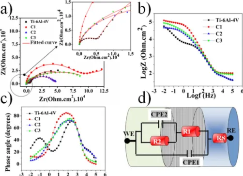
Fig. 7displays the electrochemical impedance spectroscopy results obtained for Ti-6Al-4V substrate and the coatings tested in Hank's so-lution at 37 °C. The Nyquist plot for each tested specimen appears to be arc of a semicircle (Fig. 7a). It can be easily confirmed that: (i) all the
coatings (C1, C2 and C3) show larger radius of curvature than Ti-6Al-4V substrate; (ii) two loops are clearly shown in the low and in the medium frequency range of the Nyquist plots (insert image inFig. 7a). The larger diameter of the curvature sample suggested that it offers higher resistance to charge transfer process. EIS data in Bode plots (Fig. 7(b–c)) confirm the highly electrochemical performances of C1
and the lowest performance of Ti-6Al-4V substrate. Two time constants are observed for all of the specimens. Then two capacitive behaviors occurred for the entire tested specimens. Such behaviors indicate im-proved passivefilm properties in such conditions, already observed in potentiodynamic technique (Fig. 6).
Fig. 7d indicates the selected electrical equivalent circuit model for all the specimens. This model was proposed in the literature for Ti-6Al-4V [31], Ti–6Al–4V coated Ti/TiN multilayer coatings [10] and Ti–6Al–4V coated TiO2[27].
3.2.3. Ti–6Al–4V substrate specimen
Reviewed literatures showed some controversy about the selected equivalent circuit (EC) modeling the electrochemical behavior of Ti–6Al–4V alloy in Hank's solution at 37 °C. However, all of them [27,28–35], agree that there was evidence of the formation of a two-layer oxidefilm (essentially TiO2[35]) composed of dense inner layer
and porous outer layer. In this case, the EC model consists with Hank's
solution resistance Rs. R1, CPE1 are resistance and capacitance of
porous layer (outer) with the electrolyte inside pore and R2, CPE2; resistance and capacitance of the barrier layer (inner). Detailedfitting data are listed inTable 5. The resistance of the outer layer (R1 ~ 6 kΩ)
is lower than that of the inner layer by a factor of eleven (R2 = 66 kΩ), supporting the hypothesis that the corrosion resistance is determined by the dense inner layer.
3.2.4. Ti–6Al–4V coated specimens
In the case of C1, C2 and C3 coatings, R1 is the charge transfer resistance produced by coating layer and R2 is the charge transfer re-sistance that occurs on surface of the substrate. CPE1 and CPE2 are constant phase elements used to replace the double layer capacitance of the barrier layer. In other words, R1 represents the resistance of the coating layer resulted from the coating defects (pores) and R2 is the charge transfer resistance of the coating/substrate interface. The CPE1 and CPE2 are the capacitances at the solution/coating and coating/ substrate interfaces, respectively. As can be clearly seen inFig. 7a, data adjusted well to the proposed equivalent circuit (curve in red). The chi-squared (χ2
) average values were of the order of 10−3and the error percentages corresponding to each component of the equivalent circuit was < 8%. A perfect concordance, between the experimental curve and thefitted curve was shown inFig. 7a.
The EIS results (Nyquist and Bode) show that: C1 > C3 > Ti-6Al-4V > C2. FromTable 5, the inner layer of C2 specimen (R2 = 24.65 kΩ) has a slightly higher value than the resistance related to the porous layer (R1 = 23.2 kΩ) and represents the lowest resistance when com-pared to the other specimens. At the interface coating C2/passivefilm formed in Hank's solution, the inner layer doesn't play its role as a “barrier layer”. The reason was maybe due to the low stability of this passivefilm. Indeed, Daviðsdóttir et al. [36] reported, in the case of magnetron-sputtered titanium dioxide (TiO2), that the transport of
charge between the coating and substrate depends on the activation depth of the anatase coating, and any interface oxide layer present on the substrate surface.
3.3. Tribological behavior
Quantitative results (wear volume/weight loss) of bone specimens
Table 4
Potentiodynamic polarization parameters of different coatings in Hank's solu-tion at 37 °C. Data are the average values of three tests.
Sample βa(V/dec) βc(V/dec) Ecorr(V) icorr
(A/cm2) · 10−6 Rp(Ω) Ti-6Al-4V 0.309 0.185 −0.345 0.117 490 841.17 C1 0.169 0.252 −0.071 0.049 896 077.23 C2 0.222 0.320 −0.156 0.152 364 074.30 C3 0.243 0.317 −0.142 0.105 568 623.21
Fig. 7. Electrochemical test results (EIS) in Hank's solution at 37 °C: (a) Nyquist plots, (b) Bode plots, (c) phase angle Bode plots and (d) equivalent circuit model (WE = working electrode and RE = reference electrode). (For interpretation of the references to color in thisfigure, the reader is referred to the web version of this article.)
are not so easy to obtain by simple sliding tests. In any cases they are not reproducible. The principal reason was the structural constitution of bone. As defined in literature, bone is built up of mineralized collagen fibrils [37]. The term of“structure” refers to its constitution based on the circular osteons as demonstrated in previous works [24].
3.3.1. Coefficient of friction (COF)
Fig. 8displays tribological results of tested samples against bone pins under Hank's solution lubrication condition at 37 °C.Fig. 8a shows the COF as a function of the sliding distance. At the beginning of the test, the initial COF's values are the lowest but then, they increase abruptly to a second stage. The friction coefficient of Ti-6Al-4V sub-strate was unstable and weaves around 0.6 during the total sliding distance of 100 m. It is a sign of a severe wear. C1 specimen showed the lowest values; 0.2 < COF < 0.3 before 50 m and becomes 0.3 < COF < 0.4 until the end of the test. Its average value was 0.38 (Fig. 8b). C2 and C3 reached the steady state at the beginning of the test (after a few meters of sliding) when compared to C1.
Fig. 8b displays the average value of COF at the steady-state and specific wear rates estimated based on the volume loss. It reveals that the best performance was shown by C1 specimen as expected while the worst was for the Ti-6Al-4V substrate. In thefirst stage, friction was controlled by the difference in hardness and surface roughness. Bone pin was thefirst damaged antagonist pair because it has the lowest mechanical properties. After more and more sliding cycles, an increase of temperature occurs and the surface asperities of bone are worn. Consequently the wear debris would form an adhesive oxidefilm on the
Table 5
Electrochemical impedance parameters of coatings and uncoated Ti-6Al-4V in Hank's solution at 37 °C. Data are the average values of three tests.
Sample Rs (Ω) CPE1 (μF/cm2) · E−6 α1 R1 (kΩ) CPE2 (μF/cm2) · E−6 α2 R2 (kΩ) Ti-6Al-4V 45.82 3.5 0.85 5.5 92.9 0.79 66.32 C1 99.87 1.1 0.98 75.1 43.8 0.52 107.32 C2 45.93 4.3 0.84 23.2 22.2 0.72 24.65 C3 88.67 1.6 0.94 10.4 13.6 0.51 94.590
Fig. 8. Tribological test results: (a) COF evolution and (b) estimated specific wear rates and COF values at the steady state.
Fig. 9. SEM images of the wear tracks after tribological test in Hank's solution at 37 °C of: (a) C1, (b) C2. Images (a′–b′) are the magnification of the corresponding areas in (a) and (b).
interface between the antagonist pair. Hence, the contact area increases leading to a higher friction force. Besides, hard and abrasive debris are generated from the entire tribological pair in contact (debris mixture between bone and disc) leading to the second stage characterized by a severe abrasive wear. This result (Fig. 8b) supports the COF evolution observed inFig. 8a. Nevertheless, the results ofFig. 8b should be taken with care due to the lack of data and because they are substantially lower than others obtained in the literature [23]. Besides, it is clear that Hank's solution doesn't play any role of lubrication in this contact pair.
3.3.2. Wear mechanisms analysis
The SEM images (Fig. 9) of wear tracks of two representative spe-cimens i.e. C1 and C2 show the wear mechanisms involved during the tribological tests. FromFig. 9a–b, grooves, scratches and furrows are
clearly shown, running parallel to the sliding direction (white arrows) indicating that samples have undergo a severe abrasive wear. That is the reason of a relatively high COF observed inFig. 8. Abrasion zones as well as areas outside the wear track were covered by significant quantities of wear debris (circled areas). Black arrows indicate traces of coating delamination at the edges of the wear track; that means dis-appearance of the coating after sliding tests.
The coating delamination was usually caused by the residual stresses in the substrate. However after wear tests, the detachment of the coating on either side of the wear track can occur [38]. Thefilm delamination in this case is probably due to: (i) the deterioration (abrasion) of the coating during the sliding test, layer by layer, be-coming very thin in the area of the wear track, after more and more cycles. As a consequence, the delamination of the “residual thin coating” occurred at the border of the wear track maybe when the fa-tigue strength limit of the sublayers located under the wear track was reached i.e. at the interface limit between sub-surface areas undergoing load/unload cycles and free sub-surface areas; (ii) the bonding strength (adhesion between substrate/coating) provided by the used PVD method was not sufficient enough to avoid such delamination in these specific areas.
Further,Fig. 9(a′–b′) shows on one hand, deeply imbedded debris, pores and voids (traces of removal particles) inside grooves. On another
hand, EDS analyses carried out in the wear tracks reveal the presence of bone elements (inside groove (part a′) and in dark zone (part b′)), coating elements (inside groove (part a′) and in gray zone (part b′)) and oxygen. It suggests a transfer from bone pin to coating surface.
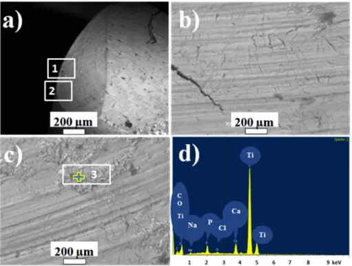
Fig. 10shows SEM images of wear scar of one bone pin taken as an example (counterpart against C1 specimen). FromFig. 10a, one can note a higher damage and deterioration of the pin in comparison to the disc. The magnified area of the worn surface shows large cracks (Fig. 10b), scratches and wear debris (Fig. 10c). EDS analyses of the wear debris (particle inside the area labeled 3 inFig. 10c) indicates the presence of oxygen, organic elements (Na, Ca, Cl, P…) and Ti (Fig. 10d). These results are signs of a third body abrasive wear me-chanism.
Finally, sliding wear of Ti-6Al-4V coated specimens according to C1 or C2 design, in Hank's solution at 37 °C undergo an oxidative wear in the initial stage followed by a third body abrasive wear. The damage process seems to be as follows: at the beginning of the test, debris products come from the bone pin. After that, the pin surface in contact against the coating specimen becomes harder and rougher as a con-sequence of friction and increase in temperature. Thus, an“adhesive film” could be created between the antagonist surfaces in contact containing hard and abrasive particles (third body). The “adhesive film” consists of a mixture between molecules (Hank's solution), frag-ments of biological tissues, collagen (bone) and Ti-nitrides, Ti-oxides particles (tested specimen) sticking together. As a result, when spe-cimen rub against bone, abrasion of the tribological pair in contact occurs.
4. Conclusion
Multilayered coatings were deposited on Ti-6Al-4V samples by DC reactive magnetron sputtering. Two types of coatings were studied: somefilms have TiN as upper layer (C1) while TiO2with 2 different
oxygen content was the top layer of the others (C2 and C3). Obtained microstructures reveal the crystallinity of TiN single phase for C1 and anatase titanium dioxide for C2 and C3 coatings. All the specimens tested in Hank's solution at 37 °C, exhibit similar electrochemical
Fig. 10. SEM images of bone pin after tribological test against specimen C1: (a) overview of the wear scar, (b) and (c) magnification of areas labeled 1 and 2, and (d) EDS Spectrum of particles analyzed in area labeled 3.
corrosion properties. The PVD layers could effectively enhance the corrosion resistance. The TiN upper layer presents the best tribological performances when against bovine cortical bone. The mean mechanism of wear involved during sliding tests was a severe third body abrasion wear. The TiO2upper layer doesn't play any role in the reduction of
friction as well as any inhibition of corrosion, regardless biocompat-ibility performances, in the conditions adopted in this study.
CRediT authorship contribution statement
R. Bahi: Formal analysis. C. Nouveau: Formal analysis. N.E. Beliardouh: Supervision, Writing - original draft, Formal analysis. C.E. Ramoul: Formal analysis. S. Meddah: Investigation. O. Ghelloudj: Investigation.
Declaration of competing interest
The authors declare that they have no known competingfinancial interests or personal relationships that could have appeared to in flu-ence the work reported in this paper.
Acknowledgements
The authors are grateful to colleagues from LaBoMaP (Arts & Métiers -Institute of Technology, Cluny, France) and LIS (Annaba, Algeria) laboratories for providing facilities to carry out this work. The authors want also to thank Dr. Aouadi Khalil for his help during the coating depositions.
References
[1] G. Mendonça, D.B.S. Mendonça, F.J.L. Aragão, L.F. Cooper, Advancing dental im-plant surface technology - from micron- to nanotopography, Biomaterials 29 (2008) 3822–3835,https://doi.org/10.1016/j.biomaterials.2008.05.012.
[2] C. Yao, T.J. Webster, Anodization: a promising nano-modification technique of ti-tanium implants for orthopedic applications, J. Nanosci. Nanotechnol. 6 (2006) 2682–2692,https://doi.org/10.1166/jnn.2006.447.
[3] W. Cui, G. Qin, J. Duan, H. Wang, A graded nano-TiN coating on biomedical Ti alloy: low friction coefficient, good bonding and biocompatibility, Mater. Sci. Eng. C 71 (2017) 520–528,https://doi.org/10.1016/j.msec.2016.10.033.
[4] M. Kaur, K. Singh, Review on titanium and titanium based alloys as biomaterials for orthopaedic applications, Mater. Sci. Eng. C (2019),https://doi.org/10.1016/j. msec.2019.04.064.
[5] H.A. Ching, D. Choudhury, M.J. Nine, N.A. Abu Osma, Effect of surface coating on reducing friction and wear of orthopedic implants, Sci. Technol. Adv. Mater. 15 (2014) 014402,https://doi.org/10.1088/1468-6996/15/1/014402.
[6] X.J. Wang, Y.C. Li, P.D. Hodgson, C.E. Wen, Nano- and macro-scale characterisation of the mechanical properties of bovine bone, Mater. Forum 31 (2007) 156–159. [7] S. Tamilselvi, H. Balaji Raghavendran, P. Srinivasan, N. Rajendran, In vitro and in
vivo studies of alkali- and heat-treated Ti-6Al-7Nb and Ti-5Al-2Nb-1Ta alloys for orthopedic implants, J. Biomed. Mater. Res. A 90 (2009) 380–386,https://doi.org/ 10.1002/jbm.a.32099.
[8] J. Guo, R.J. Padilla, W. Ambrose, I.J. De Kok, L.F. Cooper, The effect of hydrofluoric acid treatment of TiO2 grit blasted titanium implants on adherent osteoblast gene expression in vitro and in vivo, Biomaterials 28 (2007) 5418–5425,https://doi.org/ 10.1016/j.biomaterials.2007.08.032.
[9] V. Hernández-Montes, C.P. Betancur-Henao, J.F. Santa-Marín, Titanium dioxide coatings on magnesium alloys for biomaterials: a review, Dyna 84 (2017) 261–270,
https://doi.org/10.15446/dyna.v84n200.59664.
[10] K. Shukla, R. Rane, J. Alphonsa, P. Maity, S. Mukherjee, Structural, mechanical and corrosion resistance properties of Ti/TiN bilayers deposited by magnetron sput-tering on AISI 316L, Surf. Coat. Technol. 324 (2017) 167–174,https://doi.org/10. 1016/j.surfcoat.2017.05.075.
[11] L. Chenglong, Y. Dazhi, L. Guoqiang, Q. Min, Corrosion resistance and hemo-compatibility of multilayered Ti/TiN-coated surgical AISI 316L stainless steel, Mater. Lett. 59 (2005) 3813–3819,https://doi.org/10.1016/j.matlet.2005.06.058. [12] M. Herranen, U. Wiklund, J.-O. Carlsson, S. Hogmark, Corrosion behaviour of Ti/ TiN multilayer coated tool steel, Surf. Coat. Technol. 99 (1998) 191–196,https:// doi.org/10.1016/S0257-8972(97)00525-2.
[13] M. Nordin, M. Herranen, S. Hogmark, Influence of lamellae thickness on the cor-rosion behaviour of multilayered PVD TiN/CrN coatings, Thin Solid Films 348 (1999) 202–209,https://doi.org/10.1016/S0040-6090(99)00192-3.
[14] B. Tian, D.B. Xie, F.H. Wang, Corrosion behavior of TiN and TiN/Ti compositefilms
on Ti6Al4V alloy in Hank’s solution, J. Appl. Electrochem. 39 (2009) 447–453,
https://doi.org/10.1007/s10800-008-9690-4.
[15] W. Yanfeng, L. Zhengxian, W. Haonan, D. Jihong, Z. Changwei, Effect of multi-layered structure on properties of Ti/TiN coating, Rare Metal Mater. Eng. 46 (2017) 1219–1224,https://doi.org/10.1016/s1875-5372(17)30140-6.
[16] C.L. Jiang, H.L. Zhu, K.S. Shin, Y.B. Tang, Influence of titanium interlayer thickness distribution on mechanical properties of Ti/TiN multilayer coatings, Thin Solid Films 632 (2017) 97–105,https://doi.org/10.1016/j.tsf.2017.04.026. Jiang C.L. [17] E. Bogdanov, Y. Vavilina, N. Shusharina, A. Goykhman, M. Patrushev, The particles
precipitation and osseointegration of a TiO2 thin-film coating by ion beam de-position - an in vivo study, J. Nanomed. Nanotechnol. 5 (189) (2014) 1–6,https:// doi.org/10.4172/2157-7439.1000189.
[18] G. Longo, C.A. Ioannidu, A.S. D’Abusco, F. Superti, C. Misiano, R. Zanoni, et al., Improving osteoblast response in vitro by a nanostructured thinfilm with titanium carbide and titanium oxides clustered around graphitic carbon, PLoS One 11 (2016) 1–22,https://doi.org/10.1371/journal.pone.0152566.
[19] J. Heinrichs, T. Jarmar, U. Wiklund, H. Engqvist, Physical vapour deposition and bioactivity of crystalline titanium dioxide thinfilms, Trends Biomater. Artif. Organs 22 (2008) 100–106.
[20] A. Lin, M.A. Meyers, Growth and structure in abalone shell, Mater. Sci. Eng. A 390 (2005) 27–41,https://doi.org/10.1016/j.msea.2004.06.072.
[21] J.B. Park, J.D. Bronzino, Biomaterials: Principles and Applications, CRC press, Boca Raton, London, New York, Washington, D.C, 2003.
[22] C. Wang, G. Zhang, Z. Li, X. Zeng, Y. Xu, S. Zhao, et al., Tribological behavior of Ti-6Al-4V against cortical bone in different biolubricants, J. Mech. Behav. Biomed. Mater. 90 (2019) 460–471,https://doi.org/10.1016/j.jmbbm.2018.10.031. [23] C. Ramoul, N.E. Beliardouh, R. Bahi, C. Nouveau, A. Djahoudi, M.J. Walock, Surface
performances of PVD ZrN coatings in biological environments, Tribol. Mater. Surf. Interfaces 13 (2019) 12–19,https://doi.org/10.1080/17515831.2018.1553820. [24] D. Rafieian, W. Ogieglo, T. Savenije, R.G.H. Lammertink, Controlled formation of
anatase and rutile TiO2 thinfilms by reactive magnetron sputtering, AIP Adv. 5 (2015),https://doi.org/10.1063/1.4931925.
[25] A. Wiatrowski, M. Mazur, A. Obstarczyk, D. Wojcieszak, D. Kaczmarek, J. Morgiel, D. Gibson, Comparison of the physicochemical properties of TiO2 thinfilms ob-tained by magnetron sputtering with continuous and pulsed gasflow, Coatings 8 (2018) 412,https://doi.org/10.3390/coatings8110412.
[26] H. Wu, X. Zhang, X. He, M. Li, X. Huang, R. Hang, B. Tang, Wear and corrosion resistance of anti-bacterial Ti-Cu-N coatings on titanium implants, Appl. Surf. Sci. 317 (2014) 614–621,https://doi.org/10.1016/j.apsusc.2014.08.163.
[27] M. Chellappa, U. Vijayalakshmi, Improved corrosion resistant and mechanical be-havior of distinct composite coatings (silica/titania/zirconia) on Ti–6Al–4V de-posited by EPD, J. Asian Ceram. Soc. 5 (2017) 326–333,https://doi.org/10.1016/j. jascer.2017.06.005.
[28] Q. Wang, F. Zhou, C. Wang, M.F. Yuen, M. Wang, T. Qian, M. Matsumoto, J. Yan, Comparison of tribological and electrochemical properties of TiN, CrN, TiAlN and a-C:H coatings in simulated bodyfluid, Mater. Chem. Phys. 158 (2015) 74–81,
https://doi.org/10.1016/j.matchemphys.2015.03.039.
[29] N.R.N. Masdek, A.A. Rozali, M.C. Murad, Z. Salleh, Effect of protein concentration on corrosion of Ti-6Al-4V and 316L SS alloys, ISIJ Int. 58 (2018) 1519–1523,
https://doi.org/10.2355/isijinternational.isijint-2018-183.
[30] M.J. Runa, M.T. Mathew, L.A. Rocha, Tribocorrosion response of the Ti6Al4V alloys commonly used in femoral stems, Tribol. Int. 68 (2013) 85–93,https://doi.org/10. 1016/j.triboint.2013.09.022.
[31] I.C. Lavos-Valereto, S. Wolynec, I. Ramires, A.C. Guastaldi, I. Costa, Electrochemical impedance spectroscopy characterization of passivefilm formed on implant Ti-6AI-7Nb alloy in Hank’s solution, J. Mater. Sci. Mater. Med. 15 (2004) 55–59,https:// doi.org/10.1023/B:JMSM.0000010097.86245.74.
[32] F. Movassagh-Alanagh, A. Abdollah-zadeh, M. Aliofkhazraei, M. Abedi, Improving the wear and corrosion resistance of Ti–6Al–4V alloy by deposition of TiSiN na-nocomposite coating with pulsed-DC PACVD, Wear 390 (2017) 93–103,https://doi. org/10.1016/j.wear.2017.07.009.
[33] V.A. Alves, R.Q. Reis, I.C.B. Santos, D.G. Souza, T. de, M.A. Pereira-da-Silva, A. Rossi, L.A. da Silva, In situ impedance spectroscopy study of the electrochemical corrosion of Ti and Ti-6Al-4V in simulated bodyfluid at 25 °C and 37 °C, Corros. Sci. 51 (2009) 2473–2482,https://doi.org/10.1016/j.corsci.2009.06.035.
[34] I. Milošev, M. Metikoš-Huković, H.H. Strehblow, Passive film on orthopaedic TiAlV alloy formed in physiological solution investigated by X-ray photoelectron spec-troscopy, Biomaterials 21 (2000) 2103–2113, https://doi.org/10.1016/S0142-9612(00)00145-9.
[35] I.M. Pohrelyuk, V.M. Fedirko, O.V. Tkachuk, R.V. Proskurnyak, Corrosion re-sistance of Ti-6Al-4V alloy with nitride coatings in Ringer’s solution, Corros. Sci. 66 (2013) 392–398,https://doi.org/10.1016/j.corsci.2012.10.005.
[36] S. Daviðsdóttir, R. Shabadi, A.C. Galca, I.H. Andersen, K. Dirscherl, R. Ambat, Investigation of DC magnetron-sputtered TiO2 coatings: effect of coating thickness, structure, and morphology on photocatalytic activity, Appl. Surf. Sci. (2014),
https://doi.org/10.1016/j.apsusc.2014.06.047.
[37] S. Weiner, H.D. Wagner, THE MATERIAL BONE: structure-mechanical function relations, Annu. Rev. Mater. Sci. 28 (1998) 271–298,https://doi.org/10.1146/ annurev.matsci.28.1.271.
[38] A. Esguerra-Arce, N.A. Arteaga, C. Amaya, L. Ipaz, N. Alba de Sanchez, Y. Aguilar, An approximation of tribological behavior of Ti1−xAlxN coatings against animal bone in ringer’s solution, Rev. Mex. Fis. 60 (2014) 222–226.