Science Arts & Métiers (SAM)
is an open access repository that collects the work of Arts et Métiers Institute of Technology researchers and makes it freely available over the web where possible.
This is an author-deposited version published in: https://sam.ensam.eu
Handle ID: .http://hdl.handle.net/10985/17518
To cite this version :
Faissal CHEGDANI, Mohamed EL MANSORI - New Multiscale Approach for Machining Analysis of Natural Fiber Reinforced BioComposites Journal of Manufacturing Science and Engineering -Vol. 141, n°1, p.011004 - 2019
reinforced bio-composites
Faissal CHEGDANI*,a, Mohamed EL MANSORI a,b
a Arts et Métiers ParisTech, MSMP Laboratory (EA 7350), Rue Saint Dominique, BP 508, 51006, Châlons-en-Champagne, France
b Texas A&M Engineering Experiment Station, College Station, TX 77843, USA
ABSTRACT
Natural fibers are emerging in many industrial sectors to perform eco-friendly materials such as bio-composites. However, machining of natural fiber reinforced polymer (NFRP) composites remains a complex manufacturing process and the machinability of industrial components underlies a specific approach that involves the multiscale structure of natural fibers. This paper presents first a multiscale method used in machinability rating of NFRP. The fundamentals of the multiscale method are hence applied to experimentally assess the machinability of a complete industrial bio-composite part. Results show that machining NFRP composites requires specific analysis scales that are intimately linked to the natural fibrous structure. The multiscale method can be used to improve the experimental design of NFRP machining and, above all, to determine the optimum process parameters that reflect the multiscale machining characteristics of these bio-based materials.
KEYWORDS
Natural fibers; Bio-composites; Machining; Surface engineering; Multiscale analysis.
*Corresponding author: F. Chegdani
F. Chegdani & M. El Mansori
1. Introduction
Environmental constraints are becoming increasingly severe to preserve our planet. In this context, and following several economic and ecological factors, the use of natural fibers in the composite industry has proved an irreproachable success these last decades in non-structural applications [1–6]. Nowadays, several research works demonstrate the suitable use of natural fiber composites in structural applications, especially the polymer matrices that are reinforced by long plant fibers for structural applications [7–13]. Enhancing these bio-composite materials requires a scientific development of their manufacturing design for optimal properties, minimal weight, minimal cost, and minimal eco-impact [11,14].
Finishing operations (such as drilling and milling) on natural fiber reinforced polymer (NFRP) composites are hence becoming necessary to achieve the processing steps of industrial parts. Indeed, the usual manufacturing processes of composite materials cannot accomplish the near net shape of the final part (i.e. assembly holes, accurate dimensions, periphery surfaces quality, …), especially when manufacturing long fiber composites [15,16]. The existing literature has demonstrated that the machinability of composite materials is not the same as that of homogeneous materials [17–22]. The term machinability refers to the ease with which a material can be cut (machined) allowing the material removal with little cutting power, good surface finish and no wear of the cutting tool. Indeed, the machining issues in composites are due to the heterogeneity of these materials because the difference of the mechanical properties is very large between the fibers and the matrix. Then, the cutting mechanisms differ from the fibers to the matrix and, consequently, the machinability qualification of composite materials is complex and different from that of metallic materials.
In the case of NFRP composites, the machining process is more complex. Natural fibers are themselves a composite material made of cellulose microfibrils embedded in natural polymers of hemicellulose and lignin [23]. Thus, the heterogeneity is present inside each elementary fiber. Moreover, natural fibers are gathered in a bundle of dozen of elementary fibers which have random geometries and diameters [24,25]. Therefore, NFRP composites exhibit a multiscale heterogeneous structure from elementary fibers to the overall composite material through the fiber bundles (Fig. 1) [26]. Exploring the performances of NFRP materials requires a multiscale method either for manufacturing process investigation [27] or for material characterization [28].
For all these reasons, it is necessary to develop a multiscale approach to rate the machinability of natural fiber composites. Unfortunately, the edge finishing of NFRP materials are difficult and still based on empirical rules because the multiscale activated physical mechanisms are still not well understood. This is why the previous works of the authors [29–33] have focused on the multiscale analysis of the machinability for the main structures of NFRP materials.
The theory of the multiscale approach is first presented in this paper. Next, the published works on this multiscale method will be summarized. Then, a generalized multiscale approach for the machinability qualification of NFRP composites will be carried out. Finally, the validation of this new multiscale approach will be addressed by an industrial application on an automotive bio-composite part.
F. Chegdani & M. El Mansori Plant stem Ø = 2 – 3 mm Fibers bundle Ø = 100 – 500 µm Technical fiber Ø = 50 – 100 µm Elementary fiber Ø = 10 – 20 µm Cellulose microfibrils Ø = 1 – 4 nm Breaking Scutching Hackling
Fig. 1: Schematic depiction of the multiscale plant fiber structure [26].
2. Summary of the multiscale approach
The multiscale approach is based on a multiscale decomposition of topographic signals using wavelet transform. The idea is to find at which range, each material/process variable affects the morphology of the machined surface. The wavelet transform can be used by a discrete wavelet transform (DWT) [32] or a continuous wavelet transform (CWT) [31]. The aim of this wavelet transform is to decompose the global topographic signal through a series of high-pass and low-high-pass filters to analyze the high and low frequencies [34–39]. Since the high frequencies correspond to the micro-roughness and the low frequencies correspond to the waviness, the wavelet transform can quantify the surface morphology at different scale levels.
For the DWT approach, the basic functions to filter the initial topographic signal are obtained from a single prototype wavelet called the “Mother” wavelet “ψ(x)” by translation and dilation [40,41]. The mother wavelet is discretized using the Eq (1) where m and n are, respectively, the translation and dilation parameters. Then, the logarithmic scaling of both dilation and translation steps (a0 = 2 and b0 = 1) generates an orthogonal wavelet shown in
Eq (2). The DWT of the global topographic signal (called f(x)) is defined by the Eq (3) where )
(
,n x m
is the conjugate of the wavelet function. Finally, the reconstruction of the global topographic signal f(x) is given by the Eq (4).
) ( 1 ) ( 0 0 0 0 , m m m n m a a nb x a x (1) ) 2 ( 2 ) ( 2 , x x n m m n m (2) ) ( ), ( ) , (m n , x f x W mn (3)
n m n m x n m W x f , , ( ) ) , ( ) ( (4)For the CWT approach, the continuous wavelet transform of the initial topography signal f(x) is defined by the Eq (5) where a b, ,
x a b,
r
x
and r is the rotation operator defined by the Eq (6). For 2D continuous wavelet transform, x = (x,y).
In Eq (5), “a” is the contraction coefficient, b
b bx, y
the translation coefficient in the x and y directions. Therefore, each component altitude of the global topography signal “f” at the scale “a” in the “(x,y)” point coordinate fa
x, can be thus obtained in each analysis direction “θ” by inverse wavelets transform.
f x x dx a b a W f a*b , , 1 , , (5)
x,y xcos ysin xsin ycos
r (6)
After the wavelet transform, the arithmetic mean roughness can be quantified at each scale of the decomposition. This multiscale roughness is called “Ma” for 1D line topographic profiles (x) and “SMa” for 2D surface topographic profiles (x,y). This arithmetic mean value can be obtained using the Eq (7) and Eq (8) where fa(x) and fa(x,y) are respectively the component
F. Chegdani & M. El Mansori
altitude of the global topographic signal at the scale “a” in the point coordinate (x) and (x, y). “N” and “M” represent respectively the number of points in the x and the y directions.
M x a M x f a Ma 1 (7)
M x N y a MN y x f a SMa 1 1 , (8)Finally, the obtained values of Eq (7) or Eq (8) allow the determination of the multiscale process signature (MPS) which is equivalent to a transfer function that can be compared directly with the multiscale modifications of the surface topography. This MPS depicts the signatures of the finishing process in terms of essential changes of the surface state produced on the original surface [42]. The MPS is defined at each scale “a” by Eq (9) and Eq (10) for 1D line topographic profiles and 2D surface topographic profiles, respectively. In these two equations, “F” and “I” refer to final state and the initial state of the machined surfaces, respectively. 100 ) ( I a I a F a M M M a MPS (9) 100 ) ( I a I a F a SM SM SM a MPS (10)
After filtering the pertinent scales by the MPS, the mean process signature (ΔMPS) can be calculated to assess the morphology modifications due to the machining process without the parasitic effect of impertinent scales. ΔMPS is defined by Eq (11) where “P” is the number of the pertinent scales in the wavelet decomposition.
P a P a MPS MPS 1 ) ( (11)The multiscale approach proposed in this paper is based on the first-generation wavelet where the wavelet transform is obtained by dilation and translation of the mother wavelet. A
second-generation wavelet [43] exists also and uses a lifting scheme to replace the Fourier transform as its construction tool. This lifting wavelet transform gives up the dilation and translation, but it still preserves all properties of the first-generation algorithm [44]. This allows getting similar outputs between the two wavelet generations. However, the main feature of the lifting scheme is that all constructions are derived in the spatial domain. It does not require complex mathematical calculations which lead to speed-up when compared to the standard implementation [45]. Lifting wavelet transform has been applied to surface analysis of metallic and ceramic materials handled with several manufacturing processes [44]. In the case of NFRP machining and given the target scales related to natural fiber composites, first-generation wavelet is sufficient and suitable for the multiscale approach.
3. Multiscale machinability issues of NFRP composite materials
To investigate a generalized multiscale approach for the qualification of NFRP machinability, exploratory studies have been carried out by the authors on the machining of the main bio-composite structures used in industry. Thus, profile milling process has been applied to study the machinability of short fibers [29,32], unidirectional long fibers [30], and bidirectional long fibers [31] reinforced polypropylene (PP) matrices.
The exploration of short fiber composites machining shows that the standard machinability rating is not suitable for natural fiber composites [29,32]. Indeed, the fiber type effect on the machined surface quality is not revealed by considering the overall analysis scale defined by the ISO measuring length of surface roughness after machining. However, by applying the multiscale approach described in Section 2, the fiber type effect is revealed at specific scales that correspond to the meso-scale of natural fiber bundles size as shown in Fig. 2(a). The fiber bundles exhibit the fibrous structure of short fibers inside composite materials. By considering only the pertinent scales, the effect of each fiber type on the machined surfaces is
F. Chegdani & M. El Mansori Journal of Manufacturing Science and Technology
well discriminated as shown in Fig. 2(b). At this relevant scale, a mechanical criterion has been determined to rate the machinability of natural fiber composites as shown in Fig. 2(c). This mechanical criterion is the fiber stiffness (“E” in Fig. 2(b)) which is more efficient than the fiber type criterion. Indeed, the high variability of the mechanical properties of natural does not allow rating the machinability as a function of fiber type (bamboo, Miscanthus or sisal fibers). The objective mechanical criterion (i.e. fiber stiffness) will overcome the problem of the high variability of natural fibers properties that is due to the climatic conditions of growth [2]. 10 – 20 µm 200 – 500 µm 2 mm 0 100 200 300 400 500 600 0.01 0.1 1 M P Sa (% ) Scale (mm) Bamboo FRP Sisal FRP Miscanthus FRP Meso scales
Macro scales Micro scales
a 100 150 200 250 300 350 400 450 6 8 10 12 14 16 18 20 Δ M P S ( % )
Fibe r stiffness (GPa)
Feed = 0,04 mm/tooth Feed = 0,08 mm/tooth Feed = 0,12 mm/tooth 100 150 200 250 300 350 400 450 0.02 0.04 0.06 0.08 0.1 0.12 0.14 Δ M P S ( % ) Fe e d (mm/tooth) Sial: E = 7.84 GPa Miscanthus: E = 13.8 GPa Bamboo : E = 19 GPa b c
Fig. 2: a) Multiscale process signature of fiber type effect on machined surfaces of NFRP [29,32]. b) Mean process signature in function of the cutting feed for each fiber type. c) Mean process signature
in function of the fiber stiffness for each cutting feed [29,32].
The analysis of natural long fiber composites machining demonstrates, as for the natural short fiber composites, that the relevant scales to qualify the machinability are the scales that correspond to the fibrous structure size [30,31]. Indeed, both unidirectional fibers (UD) and bidirectional fibers (BD) reinforcements have the same fibrous structure of long flax fibers as continuous twisted flax yarns. Thus, regardless of the reinforcement structure (UD or BD), the relevant scales that show the effect of machining parameters are between the scale of the technical fiber size (50 µm) and the scale of fibers yarn size (1 mm) as shown in Fig. 3.
Moreover, machining of UD flax composites shows another qualification criterion which is the removed chip thickness (hm). This parameter must be higher than the edge radius of the cutting tool (rε) in order to reach the favorable cutting conditions (see Fig. 3(a)). On the other side, machining of BD flax composites shows, at the relevant scales, that the tool helix angle controls the machined surfaces quality and must be near to zero for leading to favorable cutting conditions (see Fig. 3(b)).
Pertinent scales hm = 1,6 µm hm = 3,2 µm hm = 6,4 µm hm = 12,8 µm hm = 25,6 µm hm = 51,2 µm Pertinent scales 0 0.5 1 1.5 2 2.5 3 3.5 0.01 0.1 1 M a (µ m ) Scale (mm) rε= 7.5 0.5 µm 0 0.1 0.2 0.3 0.4 0.5 0.001 0.01 0.1 1 10 M a (µ m ) Scale (mm) H=0° H=20° H=40° a b
Fig. 3: a) Multiscale machined surface roughness of UD flax/PP composites for different removed chip thickness values [30]. b) Multiscale machined surface roughness of BD flax/PP composites for
different tool helix angle values [31].
To conclude, machining of natural fiber composites requires the selection of the relevant scales for the cutting process analysis. These pertinent scales correspond to the size of the fibrous structure regardless of the reinforcement structure type. This founding has been also confirmed by an orthogonal cutting investigation on UD flax fibers reinforced PP matrix [33] which proves that the multiscale behavior of NFRP composites is independent of the process type. Indeed, the intimate relationship between the relevant scales and the fibrous structure size has been previously confirmed by nanoindentation and scratch test measurements where the authors show the scale effect on the tribo-mechanical performances of flax fibers [46,47]. Unlike glass fibers that have a homogeneous mechanical behavior, the tribo-mechanical
F. Chegdani & M. El Mansori Journal of Manufacturing Science and Technology
response of flax fibers induces a multiscale behavior that depends on the contact scale. This shows the specificity when cutting natural fibers and the importance of considering the analysis scale for robust machining of NFRP materials in structural applications.
To validate these fundamentals of the multiscale method, a complete structural NFRP composite is machined using the generalized new multiscale approach. The aim of the next section is to show the ability of the new multiscale approach to optimize the experimental design in the case of NFRP machining.
4. Multiscale machinability of industrial NFRP composite part.
4.1. Honeycomb NFRP sandwich part
The industrial part studied in this paper is an NFRP sandwich-structured composite. This kind of material structures plays a key role in the composite industry since they are typically present in many fields of structural applications. These structures result from joining, by gluing or welding, two thin composite skins on a lighter core that has lower mechanical properties. The core is generally a honeycomb structure that maintains the skins separation and transmits the mechanical actions from one skin to another as shown in Fig. 4.
Adhesive Adhesive Skin Skin Honeycomb structure Sandwich structure
Fig. 4: Schematization of a sandwich structure.
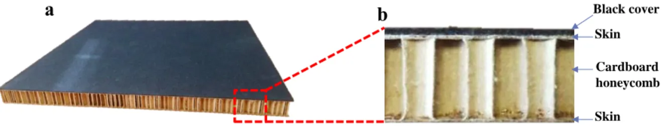
The bio-composite sandwich samples used in this study (Flaxpreg™) are provided by the automotive supplier “Faurecia – FR” and presented in Fig. 5. The skins are composite plates
molded of unidirectional flax fibers and Acrodur bio-resin. More information about the elaboration process of Flaxpreg™ can be found in [9]. The honeycomb structure is made of cardboard. Flaxpreg™ can be effectively used as a multi-position trunk loadfloor or structural floor in the passenger compartment of a vehicle. The use as reinforcement of long unidirectional non-woven flax fibers is the key innovation that allows a drastic weight reduction. Indeed, thanks to its low density using flax fibers as reinforcement in the skin and cardboard in the honeycomb structure, Flaxpreg™ offers exceptional mechanical properties allowing a weight reduction of 35% compared to traditional sandwich solutions using petro-sourced polyurethane and glass fibers reinforcement [48].
Black cover Skin Cardboard honeycomb Skin a b
Fig. 5: Flaxpreg™ sandwich-structured composite. a) 3D view. b) Profile view.
Each skin of the Flaxpreg™ sandwich consists of three layers of unidirectional long flax fibers bonded by an Acrodur resin. The density of the fibers in each layer is about 200 g/m². This gives the skin a thickness of 1 mm. The three layers of UD flax/Acrodur in each skin have 0°/90°/0° orientations of flax fibers. The thickness of the cardboard honeycomb structure is 20 mm. The black cover fabric on the composite is nonwoven needled polyethylene fibers.
4.2. Experimental design for bio-composite machining
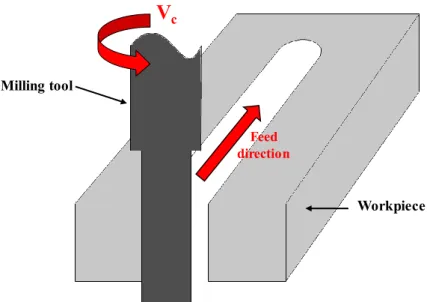
Milling experiments (Fig. 6) was realized using instrumented DMU60 monoBLOCK® five axes CNC machine. The previous works of the authors show that the favorable cutting conditions of NFRP composites are easily reached by the lowest cutting edge radius (i.e. without coating) and with zero tool helix angle [30,31]. Therefore, uncoated carbide end mill
F. Chegdani & M. El Mansori
with zero helix angle, 10 mm of diameter, 14° of rake angle and 15° of clearance angle has been used in this study. This milling tool has been supplied by “FFDM-PNEUMAT – FR” (Ref. 23N3919270). The cutting conditions related to the tool kinematics are summarized in
Table 1.
V
c Feed direction Milling tool WorkpieceFig. 6: Schematic depiction of the milling configuration used for the industrial application. Table 1: Cutting conditions used for the industrial application.
Cutting speed Vc (m/min) Feed fz (mm/tooth) 100 200 300 400 0.02 0.04 0.06 0.08 0.1
Clamping operation is among the major issues encountered when machining the sandwich-structured parts. A standard clamping between the two skin plates can damage significantly the sandwich structure. Indeed, the high concentrated compressive stresses due to the clamping can locally broke the honeycomb structure and then damage both the skin plates and the adhesive interfaces.
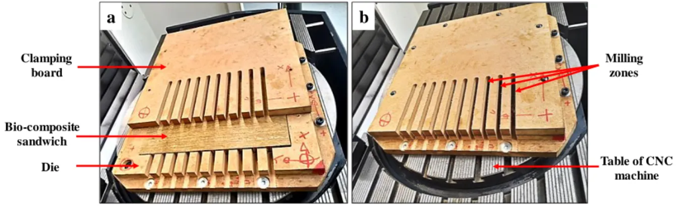
To perform an effective clamping of the sandwich part without damaging its structure, a clamping mold has been made of medium density fiberboard in order to homogeneously divide the clamping stress over the whole part and, thus, avoid its concentration on small surfaces which can damage the sandwich structure. The mold consists of two parts as shown in Fig. 7:
The bio-composite sandwich is inserted in the die part. It is composed of two levels. The lower level is larger than the outer level. The lower level is to fix the mold with the table of the 5-axis machine. The outer level has been precisely machined to contain the sandwich part.
The clamping board part is screwed onto the die part after the workpiece is inserted into the mold.
Since the depth of the die is slightly less than the thickness of the part, this system ensures effective clamping of the workpiece on the three main axes after screwing the clamp board onto the die. The milling zones on the part have been pre-machined on the mold in order to facilitate the passage of the milling tool during the machining operations.
a b Clamping board Die Bio-composite sandwich Milling zones Table of CNC machine
Fig. 7: Clamping mold of the sandwich-structured part fixed on the table of the CNC 5 axes machine. a) Before closing the clamping board. b) After closing the clamping board.
F. Chegdani & M. El Mansori
This study focuses on the profile surface state of NFRP skin (UD flax/Acrodur resin) of the bio-composite sandwich. The behaviors of the cardboard honeycomb structure and the covering fabric are not considered.
The microscopic state of the machined surfaces is evaluated by the scanning electron microscope (SEM) at low vacuum mode (Ref. JSM – 5510LV). Typical representative surface morphology as induced by milling of each experimental configuration was considered for the microscopic analysis.
The surface topography of the machined surfaces is measured by an optical interferometer (Ref. WYKO 3300NT) to show the 3D surface topography that includes the different orientations of the flax composite layers in the skin.
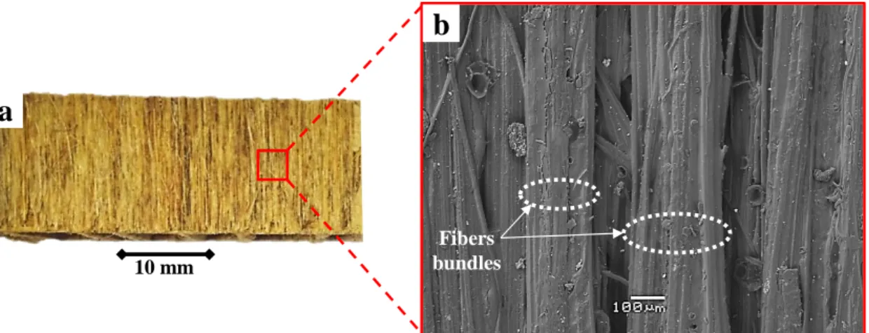
As discussed in Section 3, the relevant scales of machining analysis of NFRP composite materials are those of the fibrous structure size. In the case of the structural Flaxpreg™ sandwich part, the reinforcement is a non-woven and non-twisted unidirectional flax fibers. The relevant scales are then the scales of the technical fibers which constitute the fibrous reinforcement structure. Fig. 8(b) made by SEM shows that the size of the technical flax fibers used in this reinforcement is approximately between 150 µm and 200 μm. Consequently, the optical objective of the interferometer has been chosen and adjusted to produce topographic image dimensions that correspond to the scale of the technical fibers size.
Fibers bundles
a
b
10 mm
Fig. 8: a) Flaxpreg™ workpiece. b) SEM image of Flaxpreg™ composite skin showing the flax fibers bundles size.
4.4. Results and discussion
4.4.1. Cutting-induced surface finish
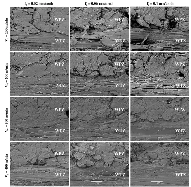
Fig. 9 illustrates SEM images of the typical microscopic surfaces state for different cutting configurations. Since the layers of the composites are oriented in the two principal directions (0° and 90°), two fiber zones are revealed: the warp fibers zone (WPZ) in which flax fibers are perpendicular to the feed direction, and the weft fiber zone (WTZ) in which flax fibers are oriented parallel to the feed direction.
F. Chegdani & M. El Mansori Vc = 100 m /m in Vc = 200 m /m in Vc = 300 m /m in
fz= 0.02 mm/tooth fz= 0.06 mm/tooth fz= 0.1 mm/tooth
Vc = 400 m /m in WPZ WTZ WPZ WTZ WPZ WTZ WPZ WTZ WPZ WTZ WPZ WTZ WPZ WTZ WPZ WTZ WPZ WTZ WPZ WTZ WPZ WTZ WPZ WTZ
Fig. 9: SEM images of machined surfaces of the flax composite skins in Flaxpreg™ for different cutting conditions.
The WTZ area is more affected by the tool feed at low cutting speed. Indeed, increasing the tool feed causes microcracks and fibers torn-off on the machined surface. By increasing the cutting speed, the tool feed effect becomes insignificant in WTZ area. At WPZ area, increasing the tool feed makes the fibers difficult to cut with exceeded fiber extremities that remain on the machined surface. Moreover, and as with the WTZ, increasing the tool feed causes also the fiber torn off. Increasing the cutting speed improves the shearing process of the fibers and reduces the tool feed effect. Nevertheless, beyond a cutting speed of 300 m/min, shearing component begins to decrease and the uncut fiber extremities are clearly shown on the machined surfaces.
Increasing the feed increases the material removal rate that leads to rising the cutting forces. Natural fibers have a high transversal flexibility that makes them very sensitive to the cutting forces. Thus, increasing the cutting forces increases the fibers deformation when the cutting contact. The flax fibers are then transversely deformed before being sheared. Therefore, flax fibers can be detached or torn off when the cutting contact because they are partially tensile stressed rather than only shearing stressed. However, when increasing the cutting speed, the material removal rate decreases and then the opposite effect occurs.
As noticed in Section 3, the previous multiscale machining studies have been performed on thermoplastic NFRP composites elaborated with PP matrix. In this paper, the considered NFRP sandwich part is elaborated with a thermoset matrix (Acrodur resin). However, This cutting behavior of flax fibers is similar to that demonstrated in the previous author’s works [30,31,33] where the same tribo-physical phenomena that occur on flax fibers during cutting process are founded via the current industrial application (fibers deformation, interfaces cracking, uncut fiber extremities, …) regardless of the matrix nature (Acrodur or polypropylene). Thus, it can be concluded that the behavior of the plant fibers during the cutting is independent of the matrix choice (thermoset or thermoplastic) used for manufacturing the NFRP composites.
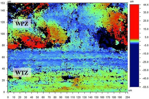
4.4.2. Multiscale surface topography of machined surfaces
Fig. 10 shows a typical topographic image by interferometer of machined surfaces on the skin profile in Flaxpreg™ sandwich structure. The WPZ zone and the WTZ zone are obvious in the image. Moreover, the fibers torn off areas can also be observed and are marked by black color. As discussed in Section 3, the developed multiscale approach postulates that the analysis scale must correspond to the size of the fibrous structure that is the technical fiber in the case of Flaxpreg™ as shown in Fig. 8. The technical fiber size is approximately between
F. Chegdani & M. El Mansori
150 µm and 200 μm, and the dimensions of the topographic image size in Fig. 10 are 153×204 µm. Therefore, the analysis scale is adapted to the fibrous structure size and thus the multiscale approach condition is satisfied. Then, the multiscale pertinent arithmetical mean height of the surface (PSMa) can be calculated from the topographic images with the image
size of Fig. 10 to quantify the surface roughness of the machined NFRP surfaces.
WPZ
WTZ
Fig. 10: Typical 3D topographic image of machined surfaces of the flax composite skins in Flaxpreg™.
Fig. 11 shows the results of the machined surfaces roughness regarding the cutting speed and
tool feed rate at the appropriate analysis scale that allows a good discrimination of process parameters effect on the surface roughness results. The surface roughness increases by increasing the feed rate and decreases by increasing the cutting speed. This corresponds to the microscopic observations. Indeed, increasing the tool feed increases the rate of the uncut fiber extremities in addition to the torn off fibers area. This increases the irregularities in the surface topography and increases the roughness. This phenomenon is more observed at low cutting velocities as shown in Fig. 9 and this is exactly what is found in terms of surface roughness since it is in these low velocities that it was the most drastic increase of the roughness as a function of the advance (Fig. 11).
Moreover, it can be found an optimum of cutting speed and feed rate for machining the Flaxpreg™ sandwich structure. The roughness is at its lowest value for an advance of 0.04 mm/tooth and for a cutting speed of 300 m/min. Consequently, these cutting conditions are the best-suited parameters for this material to guarantee the smoothest surfaces after machining with fewer surface damages.
0 1 2 3 4 5 6 7 0 100 200 300 400 500 P S M a ( µ m )
Cutting speed (m/min)
0.02 mm/tooth 0.04 mm/tooth 0.06 mm/tooth 0.08 mm/tooth 0.1 mm/tooth b 0 1 2 3 4 5 6 7 0 0.02 0.04 0.06 0.08 0.1 0.12 P S M a ( µ m ) Feed (mm/tooth) 100 m/min 200 m/min 300 m/min 400 m/min a
Fig. 11: 3D multiscale surface roughness at the pertinent scale for the machined surfaces of the flax composite skins in Flaxpreg™. a) for different cutting speed values. b) for different feed values.
F. Chegdani & M. El Mansori
5. Conclusions
This work aims to develop a multiscale approach for a suitable machinability qualification of natural fiber reinforced bio-composites. A generalized multi-scale approach for the main NFRP composite structures has been carried out. Then, an industrial application has been realized to validate the new multiscale approach on bio-composite sandwich structure. The following conclusions can be drawn:
Regardless of the natural reinforcement structure types, the pertinent scales for analyzing the machined surfaces of NFRP composites are the scales that correspond to the fibrous structure size.
The cutting behavior of plant fibers inside the composite structure is independent of the polymer matrix choice (thermoplastic or thermoset).
The industrial application on the bio-composite sandwich structure shows the strength of the developed multiscale approach for an appropriate machinability qualification of natural fiber reinforced bio-composites. The new multiscale method allows to optimize the experimental design of NFRP machining and, then, to improve the process parameters for an efficient machinability of NFRP composites.
6. Acknowledgements
The authors acknowledge the urban community of Châlons-en-Champagne (Cités en Champagne) for their financial support. The authors wish also to thank “Faurecia – Mouzon – FR” for providing the structural Flaxpreg™ sandwich composite workpieces used in this research.
7. References
[1] Shalwan, A., and Yousif, B. F., 2013, “In State of Art: Mechanical and Tribological Behaviour of Polymeric Composites Based on Natural Fibres,” Mater. Des., 48, pp. 14–24.
[2] Dittenber, D. B., and GangaRao, H. V. S., 2012, “Critical Review of Recent Publications on Use of Natural Composites in Infrastructure,” Compos. Part A Appl. Sci. Manuf., 43, pp. 1419–1429.
[3] John, M., and Thomas, S., 2008, “Biofibres and Biocomposites,” Carbohydr. Polym., 71(3), pp. 343–364.
[4] Faruk, O., Bledzki, A. K., Fink, H.-P., and Sain, M., 2012, “Biocomposites Reinforced with Natural Fibers: 2000–2010,” Prog. Polym. Sci., 37(11), pp. 1552–1596.
[5] Sobczak, L., Lang, R. W., and Haider, A., 2012, “Polypropylene Composites with Natural Fibers and Wood – General Mechanical Property Profiles,” Compos. Sci. Technol., 72(5), pp. 550–557.
[6] Wambua, P., Ivens, J., and Verpoest, I., 2003, “Natural Fibres: Can They Replace Glass in Fibre Reinforced Plastics?,” Compos. Sci. Technol., 63(9), pp. 1259–1264. [7] Shah, D. U., 2013, “Developing Plant Fibre Composites for Structural Applications by
Optimising Composite Parameters: A Critical Review,” J. Mater. Sci., 48(18), pp. 6083–6107.
[8] Koronis, G., Silva, A., and Fontul, M., 2013, “Green Composites: A Review of Adequate Materials for Automotive Applications,” Compos. Part B Eng., 44(1), pp. 120–127.
[9] Khalfallah, M., Abbès, B., Abbès, F., Guo, Y. Q., Marcel, V., Duval, A., Vanfleteren, F., and Rousseau, F., 2014, “Innovative Flax Tapes Reinforced Acrodur Biocomposites: A New Alternative for Automotive Applications,” Mater. Des., 64, pp. 116–126.
[10] Moussa, K., Valérie, M., Arnaud, D., Boussad, A., Fazilay, A., Ying Qiao, G., François, V., and Frédéric, R., 2014, “Flax/Acrodur® Sandwich Panel : An Innovative Eco-Material for Automotive Applications.,” JEC Compos. Mag., 51(89), pp. 54–59. [11] Meredith, J., Ebsworth, R., Coles, S. R., Wood, B. M., and Kirwan, K., 2012, “Natural
Fibre Composite Energy Absorption Structures,” Compos. Sci. Technol., 72(2), pp. 211–217.
[12] Jiang, L., Walczyk, D. F., and Li, B., 2018, “Modeling of Glue Penetration Into Natural Fiber Reinforcements by Roller Infusion,” J. Manuf. Sci. Eng., 140(4), p. 041006. [13] Jiang, L., Walczyk, D., and McIntyre, G., 2016, “A New Approach to Manufacturing
Biocomposite Sandwich Structures: Investigation of Preform Shell Behavior,” J. Manuf. Sci. Eng., 139(2), p. 021014.
[14] Shah, D. U., 2014, “Natural Fibre Composites: Comprehensive Ashby-Type Materials Selection Charts,” Mater. Des., 62, pp. 21–31.
[15] Davim, J. P., and Reis, P., 2005, “Damage and Dimensional Precision on Milling Carbon Fiber-Reinforced Plastics Using Design Experiments,” J. Mater. Process. Technol., 160(2), pp. 160–167.
[16] Abrate, S., and Walton, D., 1992, “Machining of Composite Materials. Part II: Non-Traditional Methods,” Compos. Manuf., 3, pp. 85–94.
F. Chegdani & M. El Mansori
Cutting of FRP – Interface Consumption Concept: A Review,” Int. J. Mech. Sci., 83, pp. 1–29.
[18] Koplev, A., Lystrup, A., and Vorm, T., 1983, “The Cutting Process, Chips, and Cutting Forces in Machining CFRP,” Composites, 14(4), pp. 371–376.
[19] Iliescu, D., Gehin, D., Iordanoff, I., Girot, F., and Gutiérrez, M. E., 2010, “A Discrete Element Method for the Simulation of CFRP Cutting,” Compos. Sci. Technol., 70(1), pp. 73–80.
[20] Bhatnagar, N., Ramakrishnan, N., Naik, N. K., and Komanduri, R., 1995, “On the Machining of Fiber Reinforced Plastic (FRP) Composite Laminates,” Int. J. Mach. Tools Manuf., 35(5), pp. 701–716.
[21] Venu Gopala Rao, G., Mahajan, P., and Bhatnagar, N., 2007, “Machining of UD-GFRP Composites Chip Formation Mechanism,” Compos. Sci. Technol., 67(11–12), pp. 2271–2281.
[22] Kim, D., Beal, A., and Kwon, P., 2015, “Effect of Tool Wear on Hole Quality in Drilling of Carbon Fiber Reinforced Plastic–Titanium Alloy Stacks Using Tungsten Carbide and Polycrystalline Diamond Tools,” J. Manuf. Sci. Eng., 138(3), p. 031006. [23] Baley, C., 2002, “Analysis of the Flax Fibres Tensile Behaviour and Analysis of the
Tensile Stiffness Increase,” Compos. - Part A Appl. Sci. Manuf., 33(7), pp. 939–948. [24] Morvan, C., Andème-Onzighi, C., Girault, R., Himmelsbach, D. S., Driouich, A., and
Akin, D. E., 2003, “Building Flax Fibres: More than One Brick in the Walls,” Plant Physiol. Biochem., 41(11–12), pp. 935–944.
[25] Hossain, R., Islam, A., Vuure, A. Van, and Verpoest, I., 2013, “Processing Dependent Flexural Strength Variation of Jute Fiber Reinforced Epoxy Composites,” J. Eng. Appl. Sci., 8(7), pp. 513–518.
[26] Bos, H. L., Molenveld, K., Teunissen, W., van Wingerde, A. M., and van Delft, D. R. V., 2004, “Compressive Behaviour of Unidirectional Flax Fibre Reinforced Composites,” J. Mater. Sci., 39(6), pp. 2159–2168.
[27] Doumbia, A. S., Castro, M., Jouannet, D., Kervoëlen, A., Falher, T., Cauret, L., and Bourmaud, A., 2015, “Flax/Polypropylene Composites for Lightened Structures: Multiscale Analysis of Process and Fibre Parameters,” Mater. Des., 87, pp. 331–341. [28] Marrot, L., Bourmaud, A., Bono, P., and Baley, C., 2014, “Multi-Scale Study of the
Adhesion between Flax Fibers and Biobased Thermoset Matrices,” Mater. Des., 62, pp. 47–56.
[29] Chegdani, F., Mezghani, S., El Mansori, M., and Mkaddem, A., 2015, “Fiber Type Effect on Tribological Behavior When Cutting Natural Fiber Reinforced Plastics,” Wear, 332–333, pp. 772–779.
[30] Chegdani, F., Mezghani, S., and El Mansori, M., 2015, “Experimental Study of Coated Tools Effects in Dry Cutting of Natural Fiber Reinforced Plastics,” Surf. Coatings Technol., 284, pp. 264–272.
[31] Chegdani, F., Mezghani, S., and El Mansori, M., 2016, “On the Multiscale Tribological Signatures of the Tool Helix Angle in Profile Milling of Woven Flax Fiber Composites,” Tribol. Int., 100, pp. 132–140.
[32] Chegdani, F., Mezghani, S., and El Mansori, M., 2017, “Correlation between Mechanical Scales and Analysis Scales of Topographic Signals under Milling Process of Natural Fibre Composites,” J. Compos. Mater., 51(19), pp. 2743–2756.
[33] Chegdani, F., and El Mansori, M., 2018, “Mechanics of Material Removal When Cutting Natural Fiber Reinforced Thermoplastic Composites,” Polym. Test., 67, pp.
275–283.
[34] Chowdhury, S. K., Nimbarte, A. D., Jaridi, M., and Creese, R. C., 2013, “Discrete Wavelet Transform Analysis of Surface Electromyography for the Fatigue Assessment of Neck and Shoulder Muscles.,” J. Electromyogr. Kinesiol., 23(5), pp. 995–1003. [35] Qiu, Z., Lee, C.-M., Xu, Z. H., and Sui, L. N., 2016, “A Multi-Resolution Filtered-x
LMS Algorithm Based on Discrete Wavelet Transform for Active Noise Control,” Mech. Syst. Signal Process., 66–67, pp. 458–469.
[36] Peng, Z. K., Jackson, M. R., Rongong, J. A., Chu, F. L., and Parkin, R. M., 2009, “On the Energy Leakage of Discrete Wavelet Transform,” Mech. Syst. Signal Process., 23(2), pp. 330–343.
[37] Chen, B., Zhang, Z., Sun, C., Li, B., Zi, Y., and He, Z., 2012, “Fault Feature Extraction of Gearbox by Using Overcomplete Rational Dilation Discrete Wavelet Transform on Signals Measured from Vibration Sensors,” Mech. Syst. Signal Process., 33, pp. 275– 298.
[38] Katunin, A., 2011, “Damage Identification in Composite Plates Using Two-Dimensional B-Spline Wavelets,” Mech. Syst. Signal Process., 25(8), pp. 3153–3167. [39] Dick, A. J., Phan, Q. M., Foley, J. R., and Spanos, P. D., 2012, “Calculating Scaling
Function Coefficients from System Response Data for New Discrete Wavelet Families,” Mech. Syst. Signal Process., 27, pp. 362–369.
[40] Chen, X., Raja, J., and Simanapalli, S., 1995, “Multi-Scale Analysis of Engineering Surfaces,” Int. J. Mach. Tools Manuf., 35(2), pp. 231–238.
[41] Daubechies, I., 1992, Ten Lectures on Wavelets, Philadelphia.
[42] El Mansori, M., Mezghani, S., Sabri, L., and Zahouani, H., 2010, “On Concept of Process Signature in Analysis of Multistage Surface Formation,” Surf. Eng., 26(3), pp. 216–223.
[43] Sweldens, W., 1996, “The Lifting Scheme: A Custom-Design Construction of Biorthogonal Wavelets,” Appl. Comput. Harmon. Anal., 3(2), pp. 186–200.
[44] Jiang, X. Q., Blunt, L., and Stout, K. J., 2000, “Development of a Lifting Wavelet Representation for Surface Characterization,” Proc. R. Soc. A Math. Phys. Eng. Sci., 456(2001), pp. 2283–2313.
[45] Daubechies, I., and Sweldens, W., 1998, “Factoring Wavelet Transforms into Lifting Steps,” J. Fourier Anal. Appl., 4(3), pp. 247–269.
[46] Chegdani, F., Wang, Z., El Mansori, M., and Bukkapatnam, S. T. S., 2018, “Multiscale Tribo-Mechanical Analysis of Natural Fiber Composites for Manufacturing Applications,” Tribol. Int., 122, pp. 143–150.
[47] Chegdani, F., El Mansori, M., Mezghani, S., and Montagne, A., 2017, “Scale Effect on Tribo-Mechanical Behavior of Vegetal Fibers in Reinforced Bio-Composite Materials,” Compos. Sci. Technol., 150, pp. 87–94.
[48] 2015, “Flaxpreg: A Composite Reinforced with Very Long Flax Fibres,” JEC Website
[Online]. Available:
http://www.jeccomposites.com/knowledge/international-composites-news/flaxpreg-composite-reinforced-very-long-flax-fibres. [Accessed: 30-Aug-2017].
![Fig. 1: Schematic depiction of the multiscale plant fiber structure [26].](https://thumb-eu.123doks.com/thumbv2/123doknet/7417966.218814/5.892.112.795.107.479/fig-schematic-depiction-multiscale-plant-fiber-structure.webp)
![Fig. 2: a) Multiscale process signature of fiber type effect on machined surfaces of NFRP [29,32]](https://thumb-eu.123doks.com/thumbv2/123doknet/7417966.218814/9.892.112.783.453.758/multiscale-process-signature-fiber-effect-machined-surfaces-nfrp.webp)
![Fig. 3: a) Multiscale machined surface roughness of UD flax/PP composites for different removed chip thickness values [30]](https://thumb-eu.123doks.com/thumbv2/123doknet/7417966.218814/10.892.118.783.381.691/multiscale-machined-surface-roughness-composites-different-removed-thickness.webp)