Science Arts & Métiers (SAM)
is an open access repository that collects the work of Arts et Métiers Institute of
Technology researchers and makes it freely available over the web where possible.
This is an author-deposited version published in:
https://sam.ensam.eu
Handle ID: .
http://hdl.handle.net/10985/16741
To cite this version :
Benjamin VAISSIER, JeanPhilippe PERNOT, Laurent CHOUGRANI, Philippe VERON
-Parametric design of graded truss lattice structures for enhanced thermal dissipation -
Computer-Aided Design - Vol. 115, p.1-12 - 2019
Any correspondence concerning this service should be sent to the repository
Administrator :
archiveouverte@ensam.eu
Parametric design of graded truss lattice structures for enhanced
thermal dissipation
✩,
✩✩Benjamin Vaissier
a,b,∗, Jean-Philippe Pernot
a, Laurent Chougrani
b, Philippe Véron
a aArts et Métiers, LISPEN EA 7515, HeSam, Aix-en-Provence, FrancebPoly-Shape, 235 rue des Canesteu, Salon-de-Provence, France
a r t i c l e i n f o
Keywords:
Truss lattice structures Additive manufacturing Parametric design Graded lattices Thermal dissipation Heat sink a b s t r a c t
Truss lattice structures are intricate geometries, whose fabrication has recently been simplified by the development of Additive Manufacturing (AM) technologies. These lightweight geometries present great volume densities and surface-to-occupancy ratios, which makes them ideal for thermal dissipation applications. This paper introduces a new framework for the parametric design of graded truss lattice structures that maximize passive cooling. It exploits the results of a semi-analytic formulation and analysis of the volume density and surface-to-occupancy ratio of state-of-the-art unit cells. In particular, it comes out that any truss lattice structure presents an optimal beam diameter over unit cell size ratio that maximizes its surface-to-occupancy value. This value and the ratio for which it is reached are identified and compared for the most common unit cells. The unit cell with the maximal surface-to-occupancy ratio is then identified, along with its set of optimal parameters, taking into account additive manufacturing constraints. The validation of this optimal geometry is performed by populating pre-defined design spaces of both academic and industrial case studies. An orientation strategy and a parametric gradation approach are also proposed to further optimize the generated heat sinks and maximize passive cooling. These results are very helpful to support decision making during the parametric design of a heat sink and to identify, a priori, the optimal unit cell, its control parameters, its orientation and its gradation strategy. The generated geometries are compared with traditional heat sink structures through static heat dissipation simulations, in order to demonstrate their interest.
1. Introduction
Recently developed Additive Manufacturing (AM) technologies are experiencing a great popularity rise among manufacturing companies, enabling the fabrication of intricate parts so far incon-ceivable [1]. Indeed, these breakthrough technologies catch the attention of many industrial fields (e.g. aerospace, automotive, defense or medical sectors) very much interested in exploring the design capabilities of AM to create high-value metallic or plastic components [2]. As opposed to subtractive manufacturing technologies, AM consists in joining materials to create objects
✩ This paper has been recommended for acceptance by Pierre Alliez, Yong-Jin Liu & Xin Li.
✩✩ No author associated with this paper has disclosed any potential or
pertinent conflicts which may be perceived to have impending conflict with this work. For full disclosure statements refer tohttps://doi.org/10.1016/j.cad. 2019.05.022.
∗
Corresponding author at: Arts et Métiers, LISPEN EA 7515, HeSam, Aix-en-Provence, France.
E-mail addresses: benjamin.vaissier@ensam.eu(B. Vaissier),
jean-philippe.pernot@ensam.eu(J.-P. Pernot).
from 3D models, usually layer upon layer [3]. Thanks to this approach, lattice [4] and porous structures, organic structures resulting from topological optimization [5], or parts with tor-tuous flow channels [6] are becoming possible and easier to manufacture. However, there still exists a gap between those newly offered manufacturing capabilities and the available design methodologies and tools, which prevents their full adoption and exploitation [7]. Thus, a paradigm shift is clearly needed by devel-oping ad-hoc models, methods and tools to support the definition and treatment of those complex shapes all along the Product Development Process (PDP).
This new way of thinking and designing the products shapes and functionalities widens the range of possibilities, allowing much more freedom for the direct embedment of advanced features, as well as for the optimization of their mechanical properties. Among them, incorporating lattice structures within the objects seems very promising to improve the performances (e.g. mass reduction, strengthening, thermal dissipation) of 3D printed products. This article focuses on the parametric design and optimization of graded truss lattice structures to enhance the heat dissipation of complex parts. It introduces a new
https://doi.org/10.1016/j.cad.2019.05.022
Fig. 1. Heat sinks designed by means of traditional fins (a), or incorporating a
graded truss lattice structure (146 629 beams) for enhanced heat dissipation (b).
framework to support the design and generation of such intricate geometries. These lightweight geometries present great volume densities and surface-to-occupancy ratios, and are therefore very well suited for the design and optimization of heat sinks.Fig. 1
shows heat sinks designed by means of traditional fins or in-corporating a graded lattice structure following the framework proposed in this paper. However, these ratios may vary depend-ing on the adopted type of unit cell, its intrinsic parameters, its orientation and gradation within the lattice structure, all of which are being studied in this paper. More precisely, this article demonstrates that any truss lattice structure presents an optimal beam diameter over unit cell size ratio that maximizes its surface-to-occupancy value. This value and the ratio for which it is reached are identified and compared for the most common state-of-the-art truss lattices. The unit cell with the maximal surface-to-occupancy ratio is then identified, along with its set of optimal parameters, taking into account additive manufacturing constraints. The validation of this optimal geometry is performed by populating pre-defined design spaces of both academic and industrial case studies. An orientation strategy and a parametric gradation approach are also proposed to further optimize the generated heat sinks and maximize passive cooling. These results are very helpful to support decision making during the parametric design of a heat sink and to identify, a priori, an optimal unit cell, its control parameters, its orientation and gradation strategy. The generated geometries are compared with traditional heat sink structures through static heat dissipation simulations.
The contribution is threefold: (i) a new framework for the parametric design of graded truss lattice structures that maximize passive cooling, (ii) a semi-analytic formulation and a theoretical analysis of the volume densities and surface-to-occupancy ratios for state-of-the-art unit cells, in order to support decision making and identify a priori the optimal unit cell and its control param-eters, (iii) an approach to generate printable well-oriented and graded truss lattice structures, in order to further enhance the dissipation performances.
The paper is organized as follows. After an overview of the cur-rent developments on thermal dissipation geometries (Section2), Section3 describes the overall framework composed of several steps. The semi-analytic formulation and the theoretical analysis of the volume densities and surface-to-occupancy ratios of the most common unit cells are detailed in Section 4. In Section5, the approach is then discussed and validated on both academic and industrial case studies, and the performances are compared with the ones obtained by other heat sinks designs. Section6ends this paper with conclusions and perspectives.
2. Related works
To cool down a system generating thermal energy, one of the classical ways is to surround the hot temperature source by a heat sink, in order to maximize the thermal exchange area between the source and its environment [8]. This simple refrigeration
mechanism is called static heat conduction or passive cooling, and this is the type of thermal dissipation considered in this article. Actually, due to their robustness and low maintenance requirements, those self-contained passive cooling technologies are much used in many industrial systems. To increase the cooling performances, an additional solution consists in creating a heat conducting fluid flow (e.g. air, water or cooling liquid) around the heat sink in order to avoid thermal accumulation at its sur-face. This approach is called forced heat convection or active cooling. It is not directly considered here, even though some of the results of this article could be exploited to extend the proposed approach for this type of dissipation. This is further discussed in the conclusion.
Because thermal energy dissipation problems are governed by partial differential equations derived from the first law of thermodynamics, the optimal heat sink geometry is generally extremely hard to find analytically when considering real-life configurations [9]. This is why, over the years, various generic ge-ometries, from the simplest to the most intricate one, have been explored and tuned to resolve this kind of problems [10]. The pros and cons of the available solutions are discussed in the next paragraphs.
Fins and pins: these simple geometries are often generated by extruding a constant cross-section in a rectilinear direction. Fins consist of thin walls regularly spaced out, whereas pins are verti-cal pillars distributed over the heating surface. The classiverti-cal rect-angular cross-section of fins can be morphed into spine shapes, in order to increase thermal dissipation efficiency [9,11]. Like-wise, the heat transfer rate of pins with a circular cross-section can be increased by shaping them like airfoils, reducing the turbulence in the convective air flow [12]. Fractal-like pins micro-structures have also been explored for the design of optimized heat sink geometries [13]. However, fins and pins, which are among the simplest heat sinks geometries, do not present optimal surface-to-occupancy ratios which limits their performance.
Open-cell foams: these lightweight metamaterials can be de-fined as porous materials with interconnected cavities. Open-cell foams present good surface-to-occupancy ratios, which make them good candidates for thermal dissipation [14,15]. Experimen-tal studies have been carried out on meExperimen-tal foams in order to have a better understanding of their geometrical [16], mechanical [17] and thermal [18] characteristics. However, because of their ran-dom nature, these properties are hard to model or simulate. This makes them unsuited for a priori parametric design, especially in the case of heat sink design [19].
Surface-based lattices: defined by the thickening of Triply-Periodic Minimal Surfaces (TPMS), which are mathematical 3D functions with zero mean curvature everywhere (locally minimiz-ing their area), surface-based lattice structures are used in partic-ular by the medical industry to generate implants with enhanced osseointegration properties [20]. Indeed, like open-cell foams, they demonstrate good surface-to-occupancy ratios, and the ex-act formulas for these ratios have long been known [21]. Para-metric optimization has even been considered to minimize the surface area of various TPMS [22]. However, despite many inves-tigations on their mechanical properties [23], very few works are focusing on TPMS thermal applications [24].
Truss lattices: defined as the aggregation of interconnected beams, truss (or beam-based) lattices can be classified into 2 sub-groups: triply periodic lattices (TPL), and stochastic lattices (SL). Both present good surface-to-occupancy ratios, which makes them good candidates for thermal dissipation. The first one con-sists of a space-filling repetition of a specific unit cell. This repetition pattern is usually made rectilinearly in 3 orthogo-nal directions, with a cubic unit cell design envelope, and 3 identical constant spacing distances. The properties of TPL with
Fig. 2. Overall framework for the parametric design and the generation of high-performance heat sinks incorporating graded lattice structures.
non-rectilinear repetitions [25], non-cubic unit cell design en-velopes and variable spacing distances have been studied. Con-trariwise, stochastic lattices correspond to beam-based structures that do not present any repetition pattern at all. The study of these structures is similar to the one of open-cell foams. There-fore, only triply periodic lattices with parallelepipedic unit cell design envelopes and non-identical constant spacing distances will be considered in this article. It is also established that the use of truss-based lattices is wide spread within the industry sector, due to their earlier emergence and the greater range of available software solutions for their design. This is why the scope of this article has been restricted in this manner. However, the dissipation performances comparison of the proposed truss-based lattices parametrization framework to equivalent work focusing on surface-based structures would be of great interest for a future paper. Like for TPMS, a lot of content can be found on mechanical responses of truss lattices [26,27], whereas fewer results are related to thermal dissipation [28,29]. In particular, in case of active cooling, the pressure loss contrasting the use of beam-based lattice structures has been experimentally high-lighted [30]. Moreover, still in case of active cooling, experimental and numerical studies allowed to evaluate the thermal properties of octet-truss [28]. Finally, a coupling between topology optimiza-tion and lattice structures generaoptimiza-tion has also been investigated to create complex structures [29].
Topology optimized geometries: also called organic structures, these geometries are generated after complex structural compu-tations. Based on Finite Element simulation, topology optimiza-tion (TO) consists in numerically removing as much material as possible from an initial design volume, while ensuring that the so-generated part geometry withstands the initially defined load case. Because they are not bound to a geometric family, the way truss or surface-based lattices can be, TO geometries are less constrained: assuming an infinitely small mesh size, the globally optimal geometry for a given problem will be one of the considered solutions. Even if mechanical optimization comes quicker to mind when talking about TO, many thermal TO in-vestigations have been carried out to identify optimal designs of 2D extruded [31,32] and 3D [33,34] heat sinks. However, TO still suffers from slow industrialization, because of its significant com-putation times, its complexity of use requiring a rare expertise, and its expensive software and hardware requirements [35].
From this literature review, several conclusions can be drawn on the design of heat sinks. First, even if few articles are looking into the use of surface-based lattices to enhance thermal ex-changes, exact formulas and parametric optimization have been detailed to optimize the surface area of TPMS. However, no equiv-alent analysis has been suggested regarding truss lattices. Ac-tually, a lot of effort has been made to study the mechanical characteristics of truss lattices, but few works consider their thermal dissipation potential. Beam-based lattices are perfectly adapted for parametric optimization. They present repetition pat-terns (unlike open-cell foams or TO geometries), they can be
defined by few simple parameters (unlike TPMS) while demon-strating enhanced surface-to-occupancy ratios (compared with pins and fins). All this makes them unquestionably well suited to thermal dissipation.
3. Overall parametric design framework
The overall framework proposed in this article allows the parametric design and the generation of heat sinks incorporat-ing graded lattice structures for high-performance passive cool-ing (Fig. 2). It is composed of several steps briefly introduced in the following paragraphs and further detailed in the next sections. Following this process, engineers can modify the values of several control parameters in order to adapt the so-generated lattice structures to their own passive cooling problem. More de-tails are given throughout the paper concerning the influence of each parameter on the resulting lattice-based heat sink geometry.
•
Design space definition: from an initial part design (that may or may not already contain a dissipative structure), the de-sign space is delimited, encompassing the maximal volume in which a heat sink structure can be generated. Together with the delimitation of the design space is thus specified a non-design space (or base design) which represents the functional surface and volume of the initial design that must be part of the final geometry to manufacture. Later on, a load case will be defined in order to specify the thermal conditions to be applied to the part.•
Lattice selection and orientation: according to the heat dissi-pation problem specificities, a unit cellκ
is selected, its size a and the beam diameter d must be identified in order to maximize the cooling efficiency, and its orientation parame-ters oκhave to be tuned in regard to the base design frame in order to further enhance the thermal dissipation. To support decision making in this particular step, engineers can exploit the results and conclusions of the semi-analytic formulation and analysis presented in Section4.•
Wireframe generation: within the design space, the overall lattice wireframe is first generated, by regularly repeating the corresponding unit cell of size a.•
Lattice volume grading and meshing: once the lattice wire-frame has been generated, the diameter of the volume sur-rounding each skeleton beam must be defined. A vertical gradation can be optionally realized, by defining a diameter value at the interface between the base design and the bottom of the heat sink (dbottom), and a diameter value atthe top of the dissipative structure (dtop). The impact of
such a gradation strategy on the overall cooling efficiency is discussed in more detail in Section 5. The meshing of the resulting volume is realized thanks to the marching cubes algorithm, but smarter approaches generating lighter numerical files can be adopted [36].
Fig. 3. Considered state-of-the-art unit cells and their acronyms.
•
Unification: the meshed heat sink geometry is finally trimmed to the design space delimitation, and merged with the part base design, forming the final part.Finally, once the final geometric model has been generated, a few preparation steps are still required before its 3D print-ing: specification of the build orientation, generation of the po-tential support structures, slice of all the parts to build and selection of the manufacturing parameters.
4. Unit cells volume density and surface-to-occupancy ratio computation and analysis
This section details the way the volume density and the surface-to-occupancy ratio are computed. The formulas are then analyzed to define design rules helpful to support decision mak-ing durmak-ing the parametric design of high-performance lattice-based heat sinks. The considered unit cells are listed in Fig. 3
together with their acronyms. Throughout this article, placed above a particular quantity, the superscript
κ
is used to highlight that the value is specific to the considered unit cell.An infinity of other unit cells could be envisioned. However, due to space limitation, only the most common academic and in-dustrial ones are considered in this article [10]. The overall frame-work and semi-analytic decomposition strategy remain anyhow valid and replicable for any unit cells.
4.1. Semi-analytic unit cell decomposition strategy
To compute the volume density and the surface-to-occupancy ratio of a unit cell, three main approaches can be distinguished. The first one is an analytic approach which consists of computing integrals over intersecting trimmed cylinders, in order to obtain exact formulas. Even though this technique leads to parametric equations which can then be differentiated to identify optimum values, in practice, the equations are complicated to define and to integrate for each unit cell [37].
Another approach is to use a 3D modeling software to generate a series of lattices with various parameter values, and to measure the volume and surface of the generated geometries. Then, a mathematical regression can be performed to identify the equa-tions that drive the evoluequa-tions of these two quantities with respect to the lattice parameters. Compared to the analytic ap-proach, this technique is flexible and easily implementable, since the parametric generation of multiple geometries is automated in most existing 3D modelers. However, as demonstrated later on in this article, the volume and surface evolutions of a unit cell are not regular across the whole parametric space. Therefore, the mathematical regression would perform badly in identifying the
Fig. 4. Decomposition strategy for the computation of the volume density and
surface-to-occupancy semi-analytic formulas (κ =GBCC ).
underlying equations, and would most likely return inaccurate formulas.
As a consequence, the decomposition strategy proposed in this article is a semi-analytic hybrid version of the two previously mentioned techniques. The main idea is to first decompose the unit cell into nodes and beams, as presented inFig. 4. Indeed, a unit cell can be decomposed into nodes of various topologies and beams of various lengths. The parametrization of the unit cells is realized through two parameters: the side size a and the beams diameter d. For a given lattice structure
κ
, let us note Nnκ the number of node topologies (or types) and Nbκthe number of beam types (with different lengths). For instance, when considering the decomposition of the GBCC unit cell ofFig. 4, it comes that NGBCCn
=
NbGBCC=
2.Once the considered unit cell has been decomposed, the vol-ume and surface of each element can be computed indepen-dently (Fig. 4). For a beam type j
∈
J1
;
Nκ
bK, the analytic formulas
SκBjand VBjκ can be easily determined. Differently, for a node type i
∈
J1
;
Nκ
nK, the evolutions of S
κ
Ni and VNiκ are identified by
mathematical regressions. The way this is performed is further detailed in Section4.3.
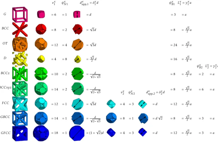
Fig. 5. The considered unit cells and cross-section views, together with the corresponding occurrence countsψNiκ, valenciesvκi and apparent diameters dapp,ifor each
node type, and the occurrence countsψNjκ and beam lengths Lκj for each beam type.
Moreover, the contribution of each element type to the overall surface and volume depends on its occurrence count. Inspired by the crystallography theory, with each node type (resp. beam type) is associated a specific occurrence count per unit cell
ψ
κNi(resp.
ψ
Bjκ) corresponding to the number of complete nodes(resp. beams) that can be created by assembling all the fraction of nodes (resp. beams) accounted for in the unit cell volume. For example, the top image ofFig. 4shows a GBCC unit cell composed of 4 vertical beams quarters and 8 horizontal beams quarters having the same length, which gives an occurrence count
ψ
GBCCB2
=
3 for this particular beam type.
Moreover, with each node type is also associated a valency
v
κi (or coordination number or ligancy in crystallography)
corre-sponding to the number of beams connected to this node. For the GBCC unit cell, the valencies of the first and second node types are respectively
v
GBCC1
=
14 andv
GBCC2=
8.Once the contribution of each element type is determined, the overall surface Sκ and volume Vκ of a unit cell can be obtained and used to compute the volume density
ρ
Vκ and surface-to-occupancy ratioρ
Sκ as described in Sections 4.4 and 4.5. From those equations, it is then possible to define the diameter-size ratio maximizing the surface-to-occupancy ratioρ
Sκ as described in Section4.7.Finally, only two parameters (side size a and beams diameter d) are required for a full parametrization of any unit cell
κ
. This is possible since the lattice structures considered in this article are only presenting Cartesian repetition patterns (so the unit cell remains cubical throughout the repetition). In the case of non-Cartesian lattice structures, more parameters would be needed to define the unit-cell geometry. However, depending on the configurations, the formulas and values obtained for Cartesianrepetitions may also remain valid and still very efficient to en-hance the thermal dissipation performances in case of non-Cartesian repetition patterns. This is illustrated in Section 5
wherein both categories of repetition patterns have been consid-ered for testing and validation.
4.2. Beams length and nodes apparent diameter
The length of the beam type j is defined by the distance between the center of its two extremity nodes. It is proportional to the unit cell side size a. Noting
γ
jκ this proportionality factor, it comes that:Lκj
=
γ
iκa,
∀j
∈
J1;
NbκK (1) Let us also define the apparent diameter dapp,i of the nodetype i, as the minimal distance from which all the connected beams are independent (i.e. are not overlapping). By geometrical considerations, it can be understood that the apparent diameter dapp,i is independent of the side size a. Actually, the apparent
diameter is only proportional to the beam diameter d, and the proportionality coefficient
δ
iκis specific to the node type i of the unit cellκ
. The following relation can therefore be written: dκapp,i=
δ
κid,
∀i
∈
J1;
NnκK (2)Fig. 5illustrates the node and beam types of each considered unit cell, with their respective occurrence counts, valencies, ap-parent diameters for the node types, and occurrence counts and lengths for the beam types. One can clearly understand that for the considered unit cells maxκ(Nnκ)
=
maxκ(Nbκ)=
2. The beam length and node apparent diameter are both used to compute the beams surface and volume analytic contributions in Section4.5.Table 1
Proportionality coefficientsαiκandβiκfor the lateral surface and volume of the considered unit cells.
Acronym (κ) ακ1 β1κ α2κ β2κ G 0.939514 0.94198377 N/A N/A BCC 3.074558 1.99338745 N/A N/A OT 3.677716 3.33365169 N/A N/A D 0.768658 0.49835000 N/A N/A BCCz 8.155219 3.88799115 N/A N/A BCCxyz 5.306663 4.42474702 N/A N/A FCC 3.677737 3.33365520 2.283168 0.90412690 GBCC 5.306663 4.42474702 3.074558 1.99338745 GFCC 11.774450 7.65076508 2.283168 0.90412690
4.3. Computation of regressions at nodes
In the proposed approach, for a node type, a series of 3D CAD models with various diameters are generated, and their respective volumes and lateral surfaces (without the circular caps resulting from the connected beams trim) are measured. Because the geometry of a node only depends of the beam diameter d, one can understand that modifying this diameter only results in a homothetic transformation (or scaling) of the node. Therefore, because of the linear properties of homothetic transformations, the volume (resp. lateral surface) of a lattice node is proportional to d3 (resp. d2). Figs. 6 and 7 present the volume and lateral
surface regressions validating this assumption for the GBCC lat-tice node of type 1. The points to be fitted have been obtained while measuring the volume (resp. lateral surface) of parametric CAD models. These proportionalities have also been observed for all the other considered unit cells, with Pearson correlation coefficients R2 above 1
−
10−8=
0.
99999999. Thus, the volumeand the lateral surface of a lattice node can be written as: SκNi
=
α
κid2,
∀i
∈
J1;
NnκK (3a)VNiκ
=
β
iκd3,
∀i
∈
J1;
NnκK (3b)Table 1lists the values of
α
iκ andβ
iκ for the two considered node types, and with respective measurement errors of±
10−6and
±
10−8.4.4. Non-overlapping parametric space
Thanks to the proposed decomposition framework, several lattice parametric design spaces can be identified. Indeed, when increasing the d
/
a ratio, there exists a certain valueσ
κfor which the node geometries of the unit cellκ
become tangent and start overlapping. This value divides the parametric space into a non-overlapping parametric space (when d/
a <σ
κ) and an overlapping one. The delimitation of these two spaces can be visualized inFig. 8for the GBCC unit cell.For the couples of parameters (d
,
a) in the overlapping para-metric space, because the lattice unit cells are only composed of node geometries, Eqs.(3a)and(3b)are not valid anymore. There-fore, the best approach to compute their surface remains the mathematical regression as explained in Section 4.3. However, the overlapping parametric space is mostly composed of closed porosity lattice designs (because of the nodes overlaps) and is thus of less interest for heat sink design. Therefore, in the rest of the paper, only couples of parameters (d,
a) in the non-overlapping space are considered, i.e. for which d/
a <σ
κ. 4.5. Volume density and surface-to-occupancy computationUsing the previously defined notations, in case of a 1 node type and 1 beam type lattice unit cell (Nnκ
=
1 and Nbκ=
1),Fig. 6. Surface regression of the GBCC lattice first node geometry.
Fig. 7. Volume regression of the GBCC lattice first node geometry.
the surface-to-occupancy ratio
ρ
Sκand the volume densityρ
Vκare computed as follows:ρ
κ S=
Sκ Vcube=
ψ
κ N1α
1κd 2+
ψ
κ B1(γ
1κa−
δ
κ1d)π
d a3 (4a)ρ
κ V=
Vκ Vcube=
ψ
κ N1β
1κd3+
ψ
B1κ(γ
1κa−
δ
1κd)π d2 4 a3 (4b)More generally, in case of a unit cell with multiple node types and multiple beam types, the surface-to-occupancy ratio and volume density are computed as follows:
ρ
κ S=
[
∑
Nκn i=1ψ
Niκα
iκ]
d2+
[
∑
Nκb j=1ψ
Bjκγ
jκa−
∑
Nκn i=1ψ
Niκv
iκδ
iκd] π
d a3 (5a)ρ
κ V=
[
∑
Nκn i=1ψ
Niκβ
iκ]
d3+
[
∑
Nκb j=1ψ
Bjκγ
jκa−
∑
Nκn i=1ψ
Niκv
κiδ
κid]
πd2 4 a3 (5b)Fig. 9illustrates how these equations are obtained, in the case of a simple 1 node type and 2 beam types lattice structure. The formulas can be simplified as follows:
ρ
κ S=
[Aκ−
Cκ] d2 a3+
D κ d a2 (6a)ρ
κ V=
[
Bκ−
C κ 4]
(
d a)
3+
D κ 4(
d a)
2 (6b)Fig. 8. Separation of parametric spaces for the GBCC unit cell.
Fig. 9. Visual details of the surface Sκ and volume Vκcomputation around a node in case of a simple 1 node type and 2 beam types lattice structure.
where Aκ, Bκ, Cκ and Dκare constants specific to each unit cell, and defined by the following equations:
Aκ
=
Nκn∑
i=1ψ
κ Niα
iκ,
and Bκ=
Nκn∑
i=1ψ
κ Niβ
iκ (7a) Cκ=
π
Nκn∑
i=1ψ
κ Niv
iκδ
iκ,
and Dκ=
π
Nκb∑
j=1ψ
κ Bjγ
jκ (7b)Finally, one can notice that the edge effects arising from the trim of the structure to its design space envelope are not taken into account. Indeed, the contribution of the lateral trimmed areas to the overall lattice surface is negligible when considering thousands of repeated unit cells.
4.6. Manufacturing requirements
Even if the design freedom provided by AM technologies al-lows the fabrication of intricate lattice structures, there still exist geometric constraints that need to be met and which are specific to each AM technology. In this paper, the considered manufactur-ing technology for the fabrication of the heat sinks is Laser Beam Melting (LBM).
An important constraint in LBM is the minimum feature size, and specifically for lattice structures, the minimum manufac-turable beam diameter. Even if it varies according to the adopted printing material, machine and manufacturing parameters, it is usual to take dmin
=
0.5 mm. Another consideration whende-signing a part for LBM production is the overhang angle. This con-straint states that any feature longer than the maximal overhang length
ℓ
ov, and forming an angle with respect to the buildplat-form lower than an overhang angle
θ
ov, must be supported [38].As for the minimum beam diameter, it varies according to the
adopted material-machine-parameters tryptic, but common val-ues are
θ
ov=
45◦
and
ℓ
ov=
1 mm.As a conclusion, the considered unit cells are not manufac-turable for any couple (d
,
a) in the parametric space. The couples (d,
a) for which the lattice structure is printable depend on the printing orientation (or balancing) of the whole part. However, as explained in Section 4.7, it is advantageous for passive heat sink design to manufacture lattices with small beam diameters d and small unit cell sizes a. For small values of these two parameters, lattice structures are manufacturable for almost any orientation.4.7. Surface-to-occupancy ratio
ρ
Sκ maximizationEqs.(6a)and(6b)show that the volume density
ρ
Vκis a third-degree polynomial of the ratio d/
a, whereas it is not the case for the surface-to-occupancyρ
Sκ. However, for a constant unit cell size a, the surface of a truss lattice is a quadratic function of d, where the second-order coefficient is Aκ−
Cκ. Actually, this coefficient is always negative. This can easily be visualized with the 3 last miniatures of Fig. 9. The surface of a lattice node is smaller than the sum of all the surfaces of the cylinders whose union are forming the lattice node. The same consideration can be made for the volume of the lattice node, which implies the two following inequalities:Cκ
>
Aκ and C κ 4>
Bκ (8)
Thus, for a constant value of a, the surface-to-occupancy func-tion presents a maximum. The value of d for which this maximum is reached can be identified by partially differentiating equa-tion (6a) with respect to d, and by finding the value of d for which it vanishes. The diameter-size relation maximizing the
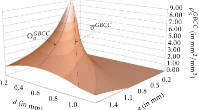
Fig. 10. Evolution of the surface-to-occupancy ratio of the GBCC unit cell
highlighting the value Ωaκ of d/a for which ρSκ is maximum (scenario a
is constant), and the value σκ of d/a which characterizes the limit of the non-overlapping parametric space.
Fig. 11. Optimal surface-to-occupancy ratios (ρκS)maxof the considered unit cells
(when d/a=Ωaκ), with respect to the beam diameter d.
surface-to-occupancy ratio
ρ
Sκis therefore defined by:∂ρ
κ S∂
d=
0⇔
d a⏐
⏐
⏐
⏐
(ρSκ)max=
Ωaκ=
D κ 2(Cκ−
Aκ) (9) If this condition is satisfied, by injecting it in Eq. (6a), the surface-to-occupancy ratio maximal value, noted (ρ
Sκ)max, can be expressed in two different ways:(
ρ
Sκ)max=
Φaκ,a×
1 a with Φ κ a,a=
Dκ2 4(Cκ−
Aκ) (10a)=
Φaκ,d×
1 d with Φ κ a,d=
Dκ3 8(Cκ−
Aκ)2 (10b) Fig. 10shows the evolution ofρ
Sκaccording to the GBCC unit cell parameters. One can clearly see both the curve characterizing the maximum ofρ
Sκdefined for the specific valueΩaκof the ratio d/
a, and the curve bounding the non-overlapping parametric space defined for the specific valueσ
κ of the ratio d/
a.A similar analysis could be performed for a constant value of d. Indeed, there exists a value of a maximizing the surface-to-occupancy ratio
ρ
Sκ. Likewise, this value can be identified by partially differentiating equation(6a)with respect to a. This leads to a different d/
a ratio, notedΩdκ, and different values of the coefficientsΦdκ,aandΦdκ,dused to compute (ρ
Sκ)max. Due to spacelimitations, these equations are not provided here.
Depending on the encountered scenario, i.e. whether the en-gineer chooses to fix the value of a or the value of d, either the coefficient Ωaκ or Ωdκ must be used to determine the optimal
Table 2
Values ofΩaκ andΩdκmaximizing the surface-to-occupancy ratio.
Acronym (κ) Ωaκ Ωκd G 0.55536151 0.74048200 BCC 0.37023936 0.49365247 OT 0.230036924 0.306715899 D 0.3702412 0.4936549 BCCz 0.31600360 0.42133813 BCCxyz 0.273120323 0.364160430 FCC 0.32532145 0.43376193 GBCC 0.30063617 0.40084823 GFCC 0.26342710 0.35123614 Table 3
Volume densities which maximize surface-to-occupancy ratios.
Acronym (κ) ρVκwhen d/a=Ωκa ρVκwhen d/a=Ωdκ
G 48.4% 71.4% BCC 49.7% 73.7% OT 47.0% 69.7% D 49.7% 73.7% BCCz 46.7% 69.2% BCCxyz 50.5% 74.8% FCC 47.0% 69.7% GBCC 47.0% 69.6% GFCC 41.7% 61.8%
value of the other parameter, thus maximizing the surface-to-occupancy ratio
ρ
Sκ.Table 2 gathers all the values ofΩaκ and Ωdκ for the consid-ered lattice structures. The errors lie in between 10−6 and 10−8,
which is very low, and this proves that the adopted semi-analytic decomposition strategy is valid. Of course, during the parametric design, when tuning their parameters, designers do not need that much accuracy and some values will be rounded.Fig. 11displays the evolutions of Eq.(10b)for the considered unit cells, i.e. the surface-to-occupancy evolutions according to the beam diameter d, in the case where d
/
a follows Eq. (9). On this figure is also displayed in red the values of d unsuited for LBM production (d<
dmin=
0.5 mm).Finally, maximizing the surface-to-occupancy ratio is useful for a heat dissipation problem with a fixed design space. How-ever, for applications such as aerospace or automotive, one other crucial constraint is the weight of the heat sink, which can directly be correlated to the volume densities
ρ
Vκ of the unit cells. Thus, to further characterize the performance with respect to weight issues, the values ofρ
Vκmust be computed when the re-spective surface-to-occupancyρ
Sκratios are maximized. It means that the ratio d/
a is constant and follows Eq.(9). Because the volume density of a particular lattice is a third-order polynomial of ratio d/
a, when Eq. (9)is met, the volume densityρ
Vκ of the unit cellκ
is constant. When considering the design scenario for which a is constant, the value ofρ
Vκ can be obtained by injecting the value ofΩaκinto Eq.(6b). Reversely, for the scenario with d constant,Ωdκ has to be used.Table 3 lists the constant values ofρ
κV, when the respective surface-to-occupancy ratios are maximized for the two design scenarios (i.e. a or d specified by the designer). This table helps the designer in identifying the most suited unit cell when considering the weight constraint.4.8. Synthesis
The equations of the surface-to-occupancy ratio and volume density of any unit cell have been formulated, and numerical val-ues have been computed for the most common ones. Using these results, and depending on their design requirements, engineers can select an appropriate unit cell and tune its control parameters (a
,
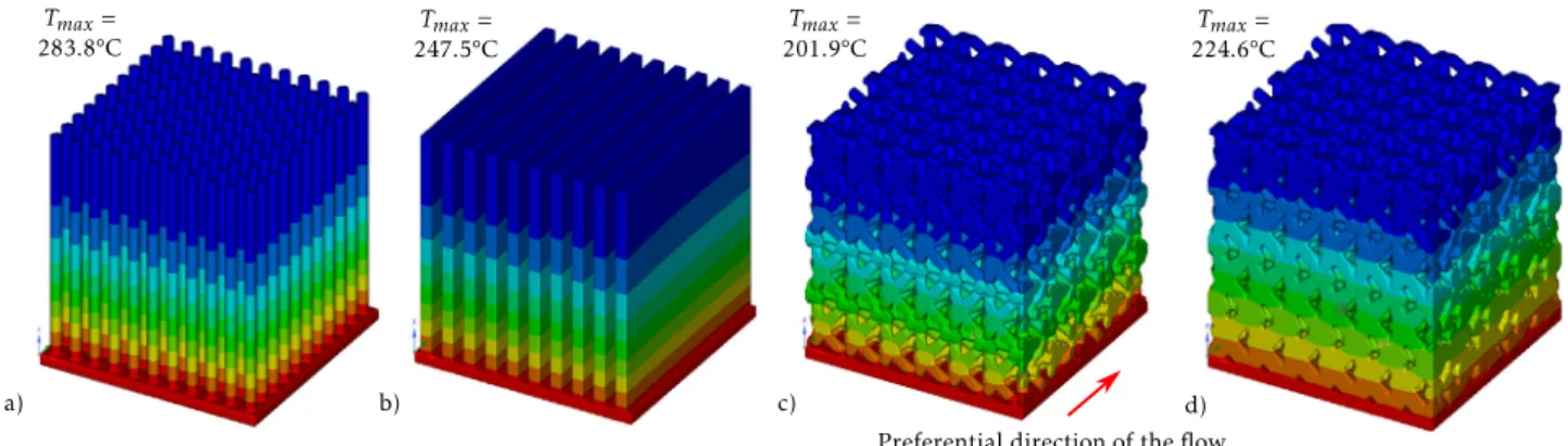
d) to maximize the surface-to-occupancy ratio, and remainFig. 12. Simulation results for the academic test case with pin-based (a), fin-based (b), regular oriented lattice (c), and graded oriented lattice (d) dissipative structures.
in the manufacturable area as well as in the non-overlapping parametric space. Moreover, this parametric analysis leads to the following findings:
•
Two design scenarios can be followed and lead to the use of different coefficients: when the designer decides to fix the value of the cell size a, then he/she has to find the value of d usingΩaκ, reversely if d is fixed, then a is obtained with equation a=
d/
Ωdκ.•
If the couple (a,
d) is chosen such that d/
a=
Ωaκ or d/
a=
Ωκ
d, then necessarily d
/
a< σ
κand the node geometries arenot overlapping. This is straightforward when analyzing the relative position of the two curves ofFig. 10.
•
The BCCxyz unit cell reveals a slightly higher surface-to-occupancy ratio than the others. This is thus the one se-lected for the experimentations and for the validation in Section5.Finally, the formulas and findings presented in this section are valid for Cartesian lattice structures, and this covers most of the industrial situations. However, the overall framework and the semi-analytic decomposition scheme remain adapted for non-Cartesian repetition patterns. In this case, new parameters would notably appear and the formulas would significantly change.
5. Experimentations and results
The parametric analysis performed on various unit cells has demonstrated the existence of an optimal ratio d
/
a that maxi-mizes the surface-to-occupancy ratio of the structure. However, even though it is straightforward that the thermal exchange surface has an important impact on the performances of a pas-sive dissipative structure, it is not the only parameter that can influence them. This section considers a design scenario for which a is fixed by the designer. It demonstrates through numerical experiments that a lattice structure generated with the previously identified d/
a=
Ωaκ value is indeed the optimal structure con-sidering the thermal dissipation performances. It also shows that the findings obtained for Cartesian repetition patterns may still be of interest to enhance the thermal dissipation performances of non-Cartesian lattice structures.5.1. Numerical validation on an academic test case
The experiments and the numerical validation have been re-alized on an academic test case, represented by a 0.5 mm thick plate, shaped like a square of 10 mm side. The thermal load case consists of a 5 W heat flux applied at the bottom face of the plate. All the dissipative structures compared in the following paragraphs are encompassed in a 10 mm side cube located above the top face of the plate, which corresponds to the heat sink
Table 4
Parameters used for the simulation of the academic test case. Simulation parameters
Thermal conductivity of solid materialλ 148.62 W m−1◦
C−1
Convective heat transfer coefficient 10 W m−2◦
C−1
Ambient temperature 20◦
C
design space. The material chosen for the simulations is Alu-minum. Indeed, it is a common AM printing material, presenting great thermal properties. This article focuses on passive cooling applications, and the simulations are thus realized accordingly: the conduction of the heat through the solid material (namely the lattice structure) is modelized along with the heat convection between the solid material and the surrounding air. Specifically, the thermal conductivity within the solid material is proportional to the temperature gradient within the lattice structure, and the convection between the lattice structure and the surrounding air (modelized through the convective heat transfer coefficient) is proportional to the temperature difference between the solid material and the fluid. The performance of a particular dissipative structure is measured through the maximal temperature Tmax of
the whole part when the steady state is reached. These simu-lations have been realized with Ansys Discovery Live, using the parameters listed inTable 4.
Following the proposed parametric design framework, once the design space is defined, the next step consists in selecting the unit cell (Fig. 2). Here, the BCCxyz unit cell has been selected since, as visible in Fig. 11, it presents the highest surface-to-occupancy maximal value (
ρ
Sκ)max for the considered scenario(i.e. a constant value of a).
As a reminder, the scope of this article is to consider a static heat dissipation problem. However, even for a non moving part without any fluid stream generating device, one cannot com-pletely ignore the existence of a fluid flow circulating through the heat sink structure. Keeping in mind this element, the best orientation for the adopted lattice structure is selected. For the BCCxyz unit cell,Fig. 13illustrates three possible orientations in the case of a fluid flow perpendicular to the figure plane. It clearly shows that the isometric orientation (c) is the one with the largest pores, letting more easily the surrounding fluid go through the dissipative lattice structure. This is therefore the oκ orientation adopted for the generation of the BCCxyz lattice structure. As it will be shown in the next subsection, this ideal orientation can be used to drive the generation of the entire wireframe while following both linear and curved repetition paths.
The first set of simulations are realized on non-graded lattice structures, with constant unit cell size a
=
1.
83 mm, such as the one of Fig. 12.c. Indeed, this is the value of the unit cell size for which the optimal beam diameter d is equal toFig. 13. Front (a), side (b) and isometric (c) views of BCCxyz unit cell.
Fig. 14. Maximal temperature in the regular lattice of the academic test case
when steady state is reached according to the beam diameter d.
Ωκ
a
×a
=
0.5 mm. To demonstrate the optimality of this beamdi-ameter value, the simulations are realized on structures present-ing various beam diameters d, rangpresent-ing from 0.4 mm to 0.6 mm. In
Fig. 14representing the output results of these simulations, one can see that the minimal value for Tmaxis indeed obtained when
the beam diameter d
=
0.
5 mm. These results demonstrate that choosing the right set of values for the parameters couple (a,
d) leads to the best thermal dissipation performances, in the case of a non-graded lattice design. The resulting temperature Tmaxis also compared to the ones obtained in the case of fin-basedand pin-based dissipative structures (Fig. 12.a to c). The feature sizes of these structures have been defined equal to the beam diameter of the compared lattice structure, specifically 0.5 mm, for the comparison to be fair. The differences between the Tmax
values of the three first simulations ofFig. 12, clearly illustrate the interest of using a well parametrized lattice-based structure for static heat dissipation applications.
However, in a passive thermal dissipative problem, heat con-duction through the solid material plays an important part in the obtention of the best performances. By homogenizing the distribution of the heat throughout the whole geometry of the heat sink, one can increase the overall thermal exchanges with the surrounding fluid and enhance the general performance of the dissipative structure. This is characteristic of thermal Topology Optimization results, generally demonstrating massive trunks at their base, with thinner ramifications as the structure grows away from the heat source. In the case of a lattice structure, this variation of volume density enhancing the thermal conductiv-ity can be realized through a gradation of the beam diameter, from the bottom to the top of the dissipative structure. In case of a linear gradation strategy, two diameter values are needed, namely dbottom and dtop, with dbottom
≥
dtop. While keeping dtopto its minimum manufacturable value of 0.5 mm, several test geometries have been simulated by varying the value of dbottom
from 0.5 mm to 0.8 mm. However, because the adopted starting beam diameter value (dtop
=
0.
5 mm) maximizes thesurface-to-Fig. 15. Variation of the maximal temperature Tmaxaccording to the dbottomvalue
of graded lattice structures (dtop=0.5 mm).
occupancy ratio, this gradation is realized at the expense of the exchange surface of the structure. This is why, analyzing the mea-sured values of Tmaxfor each of the simulations plotted inFig. 15,
one can see that only a slight gradation of the beam diameter over the height of the lattice structure uniformizes indeed the temperature distribution throughout the structure, enhancing its thermal dissipative properties. Formulated differently, the trade-off made on the surface exchange to ensure a better temperature distribution quickly becomes unfavorable with respect to the thermal dissipation performance of the whole structure. From
Fig. 15, a dbottom
=
0.
53 mm appears to be the best compromise,and this value will therefore be adopted for the gradation of the industrial test case. Such a low-amplitude gradation (d
∈
[
0.
5..
0.
53]
) can hardly be visually detected. Thus, to see the gradation, the simulation ofFig. 12.d has been performed using a higher gradation amplitude (dbottom=
0.
8 mm) and it correspondsto the one on the right of Fig. 15, thus resulting in a higher Tmaxvalue.
5.2. Industrial case studies
Two different industrial case studies are considered for testing and validation: the redesign of an oil tank carter and of a bent pipe. The first case study requires Cartesian repetition patterns, whereas the second makes use of non-Cartesian lattice struc-tures. Hot oil is circulating under the carter and inside the pipe, and needs to be cooled down. In both cases, the constant heat flux that needs to be dissipated is equal to 15 W, and the parameters used for the simulations are the ones used for the academic test case (Table 4).
Fig. 16.a presents the initial design of the carter. On this design version, the heat dissipation is thus realized through thin fins located above the carter. Following the proposed design frame-work, a maximal design space is first delimited from the initial design (Fig. 16.a), with the carter base blank of any heat dissipa-tion structure. According to the parametric analysis of Secdissipa-tion4.5, a wisely parametrized lattice-based heat sink is generated above the carter base (Fig. 16.b), and its dissipation performances are compared to the ones of the initial design. The lattice unit cell adopted for this industrial case study is still the BCCxyz, oriented identically as for the academic test case. The generation of the lattice wireframe is realized within the pre-defined design space, along the main Cartesian directions, with a unit cell size equal to 1.83 mm. Overall, 146 629 beams are generated. A graded volume is then generated around the wireframe, with an optimal dbottom
value equal to 0.53 mm and dtopstill selected at the limit of the
Fig. 16. Initial design and deduced design space of an industrial oil tank carter
(a), and graded oriented lattice-based heat sink (b).
Fig. 17. Simulations of the initial (a) and final (b) designs of the industrial carter
case study.
Fig. 18. Simulations of the initial (a) and final (b) designs of the industrial bent
pipe case study.
adopted based on the previously analyzed simulations ofFig. 15, demonstrating that a low gradation is preferential with small beam diameter values. The simulation result of the redesigned version of the carter is compared to the one of the initial version that uses vertical dissipative fins (Fig. 17). One can clearly see that Tmax has significantly been reduced from 81.3◦C to 54.6◦C. This
comparison validates the proposed approach for the design of high-performance heat sinks.
The proposed parametric design approach has also been fol-lowed to improve the design of a bent pipe. The initial design is made of 32 fins surrounding the pipe and bent to follow the evolution of its shape. The simulation result of this initial design highlights a Tmax
=
76.
1◦C (Fig. 18.a). Starting from thisversion, a pre-defined design space is identified and filled in with a lattice structure whose repetitions follow the shape of the bent pipe. Overall, 64 320 beams are generated with a unit cell size equal to 1.83 mm and a constant beam diameter of 0.5 mm. To follow this curved non-Cartesian repetition pattern, each unit cell is slightly stretched and rotated along the path. Here again, when compared to classical fins, the simulation results clearly demonstrate the interest of using truss lattice structures for the design of high-performance heat sinks (Fig. 18.b). This example also shows that, even though the adopted parameters a and
d cannot be anymore considered as optimal (because the formulas used to obtain them are valid for Cartesian repetition schemes), their use still helps to improve the overall performance of the heat sink. Actually, in the present case, the unit cells are not stretched that much as the angular variation between two neigh-bor cells does not exceed 4.1◦. Thus, using the formulas obtained for Cartesian repetitions can still be considered as a good approx-imation. Of course, while defining a proper parametrization of this particular example, and while identifying the corresponding new formulas, one could find out new optimal values for the unit cells parameters so as to further improve the thermal dissipation performances.
6. Conclusions and future works
This article has introduced a new framework for the para-metric design of graded truss lattices that maximize passive cooling. The geometry of these intricate structures is controlled by several parameters related to the type of unit cell
κ
used to populate a design space, the unit cell size a and beam diameter d, its orientation parameters oκ in regard to the base design frame, the gradation parameters dtopand dbottom. A semi-analyticdecomposition strategy has been proposed to study the volume density and the surface-to-occupancy ratio of state-of-the-art unit cells. In particular, a parametric analysis (whose parame-ters were the beam diameter d and the unit cell size a of the lattice structure) allowed to identify the underlying equations followed by these two quantities. The values Ωaκ (resp. Ωdκ) of the ratio d
/
a that maximize the surface-to-occupancy ra-tio of each unit cell have been identified and should be used when the designer fixes the cell size a (resp. the beam di-ameter d). The experimentations and results have shown that the proposed approach helps designing lattice-based heat sinks with enhanced thermal dissipation performances, compared to traditional fins-based geometries. Even though the perimeter of this paper has been restricted to Cartesian lattices, the proposed approach can easily be extended to structures presenting non-Cartesian repetition patterns. An example of such a possibility has been presented where the unit cells are stretched and rotated along free-form curves. Actually, when considering slight shape deviations from a perfectly cubic unit cell, the formulas obtained for Cartesian repetition schemes can still be considered as a good approximation.The scope of this article was restricted to the case of passive cooling. Because of their low manufacturing costs and mainte-nance requirements, static heat sinks are widely used. However, for specific applications involving high heat generation sources, the performances can be greatly enhanced by the presence of a naturally or artificially induced fluid stream through the heat sink.
In the case of such an active heat dissipation problem, the present study is a great starting point and, through the proposed framework, designers still have access to all the control param-eters. Indeed, maximizing the exchange area between the heat sink and the surrounding fluid is still a crucial aspect in such configuration. The beam diameter over the unit cell size ratio maximizing the surface-to-occupancy ratio, namely Ωaκ or Ωdκ, gives therefore a first part of the solution. However, selecting d as low as possible with respect to the manufacturing capabilities is not the best approach anymore. The two parameters d and a being coupled through the value of Ωaκ or Ωdκ, the smaller d is, the smaller the pores of the lattice structure are, preventing the fluid stream from correctly circulating through the heat sink (a phenomenon known as pressure loss). Another parametric analysis of the pressure loss of a specific lattice according to the same parameters a and d would enable the identification
of another optimal couple (d
,
a). Furthermore, according to their orientation oκ, some lattice unit cells are demonstrating bigger pores with respect to a and d. Thus, prioritizing the selection of a lattice unit cellκ
with a higher pore size with respect to a and d, but with a slightly lower surface-to-occupancy ratio might be preferential for an active heat dissipation problem.Finally, this paper has been focusing on optimizing the surface-to-occupancy ratio of truss-based lattice structures. How-ever, multi-objective problems can arise when trying to resolve heat dissipation problems, in particular when the volume or the structural response of the resulting dissipation structure must be controlled. Since analytic formulas of truss-based lattices sur-faces have been provided in this paper, the extension of this work to multi-objective optimization will be facilitated for future works.
References
[1] Gao W, Zhang Y, Ramanujan D, Ramani K, Chen Y, Williams CB, Wang CC, Shin YC, Zhang S, Zavattieri PD. The status, challenges, and future of additive manufacturing in engineering. Comput Aided Des 2015;69:65–89.
[2] Tofail SA, Koumoulos EP, Bandyopadhyay A, Bose S, ODonoghue L, Char-itidis C. Additive manufacturing: scientific and technological challenges, market uptake and opportunities. Materials Today 2018;21(1):22–37.
[3] ASTM F2792-12a, Standard Terminology for Additive Manufacturing Technologies, (Withdrawn 2015) 2012.
[4] Tang Y, Kurtz A, Zhao YF. Bidirectional evolutionary structural optimization (BESO) based design method for lattice structure to be fabricated by additive manufacturing. Comput Aided Des 2015;69:91–101.
[5] Panesar A, Abdi M, Hickman D, Ashcroft I. Strategies for functionally graded lattice structures derived using topology optimisation for additive manufacturing. Additive Manuf 2018;19:81–94.
[6] Brooks H, Brigden K. Design of conformal cooling layers with self-supporting lattices for additively manufactured tooling. Additive Manuf 2016;11:16–22.
[7] Schmelzle J, Kline EV, Dickman CJ, Reutzel EW, Jones G, Simpson TW. (Re)designing for part consolidation: Understanding the challenges of metal additive manufacturing. J Mech Des 2015;137(11):111404.
[8] Ahmed HE, Salman B, Kherbeet A, Ahmed M. Optimization of thermal design of heat sinks: A review. Int J Heat Mass Transfer 2018;118:129–53.
[9] Kraus AD, Aziz A, Welty JR. Extended surface heat transfer. New York: John Wiley; 2001.
[10] Jafari D, Wits WW. The utilization of selective laser melting technology on heat transfer devices for thermal energy conversion applications: A review. Renew Sustain Energy Rev 2018;91:420–42.
[11] Pirompugd W, Wongwises S. Efficiencies for partially wetted spine fins: Uniform cross section, conical, concave parabolic, and convex parabolic spines. J Heat Transfer 2013;135(8).
[12] Ho J, Wong K, Leong K, Wong T. Convective heat transfer performance of airfoil heat sinks fabricated by selective laser melting. Int J Therm Sci 2017;114:213–28.
[13] Massarwi F, Machchhar J, Antolin P, Elber G. Hierarchical, random and bifurcation tiling with heterogeneity in micro-structures construction via functional composition. Comput Aided Des 2018;102:148–59.
[14] Ashby MF, Evans AG, Fleck NA, Gibson LJ, Hutchinson JW, Wadley HNG. Metal Foams: A Design Guide 263.
[15] Mahjoob S, Vafai K. A synthesis of fluid and thermal transport models for metal foam heat exchangers. Int J Heat Mass Transfer 2008;51(15–16):3701–11.
[16] Nie Z, Lin Y, Tong Q. Modeling structures of open cell foams. Comput Mater Sci 2017;131:160–9.
[17] Murr L, Gaytan S, Medina F, Martinez E, Martinez J, Hernandez D, Machado B, Ramirez D, Wicker R. Characterization of ti-6al-4v open cellular foams fabricated by additive manufacturing using electron beam melting. Mater Sci Eng A 2010;527(7–8):1861–8.
[18] Wu D, Huang C. Thermal conductivity model of open-cell foam suitable for wide span of porosities. Int J Heat Mass Transfer 2019;130:1075–86.
[19] Feng S, Kuang J, Wen T, Lu T, Ichimiya K. An experimental and numerical study of finned metal foam heat sinks under impinging air jet cooling. Int J Heat Mass Transfer 2014;77:1063–74.
[20] Mahmoud D, Elbestawi M. Lattice structures and functionally graded materials applications in additive manufacturing of orthopedic implants: A review. J Manuf Mater Process 2017;1(2):13.
[21] Gandy PJF, Cvijovic D, Mackay AL, Klinowski J. Exact computation of the triply periodic d ’diamond’/ minimal surface. Chem Phys Lett 1999;9.
[22] Yang S-D, Lee HG, Kim J. A phase-field approach for minimizing the area of triply periodic surfaces with volume constraint. Comput Phys Comm 2010;181(6):1037–46.
[23] Li D, Liao W, Dai N, Dong G, Tang Y, Xie YM. Optimal design and mod-eling of gyroid-based functionally graded cellular structures for additive manufacturing. Comput Aided Des 2018;104:87–99.
[24] Abueidda DW, Abu Al-Rub RK, Dalaq AS, Lee D-W, Khan KA, Jasiuk I. Effective conductivities and elastic moduli of novel foams with triply periodic minimal surfaces. Mech Mater 2016;95:102–15.
[25] Rumpf RC, Pazos J. Synthesis of spatially variant lattices. Opt Express 2012;20(14):15263.
[26] Dong G, Tang Y, Zhao YF. A survey of modeling of lattice structures fabricated by additive manufacturing. J Mech Des 2017;139(10):100906.
[27] Rashed M, Ashraf M, Mines R, Hazell PJ. Metallic microlattice materials: A current state of the art on manufacturing, mechanical properties and applications. Mater Des 2016;95:518–33.
[28] Ekade P, Krishnan S. Fluid flow and heat transfer characteristics of octet truss lattice geometry. Int J Therm Sci 2019;137:253–61.
[29] Cheng L, Liu J, Liang X, To AC. Coupling lattice structure topology optimization with design-dependent feature evolution for additive man-ufactured heat conduction design. Comput Methods Appl Mech Engrg 2018;332:408–39.
[30] Wong M, Owen I, Sutcliffe C, Puri A. Convective heat transfer and pressure losses across novel heat sinks fabricated by selective laser melting. Int J Heat and Mass Transfer 2009;52(1–2):281–8.
[31] Joo Y, Lee I, Kim SJ. Topology optimization of heat sinks in natural con-vection considering the effect of shape-dependent heat transfer coefficient. Int J Heat Mass Transfer 2017;109:123–33.
[32] Bornoff R, Parry J. An additive design heatsink geometry topology identi-fication and optimisation algorithm. In: 2015 31st Thermal Measurement, Modeling & Management Symposium (SEMI-THERM). San Jose, CA, USA: IEEE; 2015, p. 303–8.
[33] Lazarov BS, Sigmund O, Meyer KE, Alexandersen J. Experimental validation of additively manufactured optimized shapes for passive cooling. Appl Energy 2018;226:330–9.
[34] Alexandersen J, Sigmund O, Aage N. Large scale three-dimensional topology optimisation of heat sinks cooled by natural convection. Int J Heat Mass Transfer 2016;100:876–91.
[35] Dbouk T. A review about the engineering design of optimal heat transfer systems using topology optimization. Appl Therm Eng 2017;112:841–54.
[36] Chougrani L, Pernot J-P, Véron P, Abed S. Lattice structure lightweight triangulation for additive manufacturing. Comput Aided Des 2017;90: 95–104.
[37] ElMaraghy W, Valluri S, Skubnik B, Surry P. Intersection volumes and surface areas of cylinders for geometrical modelling and tolerancing. Comput Aided Des 1994;26(1):29–45.
[38] Vaissier B, Pernot J-P, Chougrani L, Véron P. Genetic-algorithm based framework for lattice support structure optimization in additive manufacturing. Comput Aided Des 2019;110:11–23.