Technology researchers and makes it freely available over the web where possible.
This is an author-deposited version published in: https://sam.ensam.eu
Handle ID: .http://hdl.handle.net/10985/10071
To cite this version :
Hocine CHALAL, Abdellah SALAHOUELHADJ, Farid ABED-MERAIM - Evaluation of a new solid-shell finite element on the simulation of sheet metal forming processes - In: 14th International Conference on Metal Forming, September 16-19, 2012, AGH University of Science and Technology, Pologne, 2012-09 - Metal Forming 2012 proceedings of the 14th International Conference on Metal Forming - 2012
Evaluation of a New Solid–Shell Finite Element on the Simulation of Sheet Metal
Forming Processes
Hocine Chalal, Abdellah Salahouelhadj, Farid Abed-Meraim
Laboratoire d’Étude des Microstructures et de Mécanique des Matériaux, LEM3, UMR CNRS 7239, Arts et Métiers ParisTech, 4 rue Augustin Fresnel, 57078 Metz Cedex 03, France, [email protected]
Abstract. In this paper, the performance of the solid–shell finite element SHB8PS is assessed in the context of sheet metal forming simu-lation using anisotropic elastic–plastic behavior models. This finite element technology has been implemented into the commercial implicit finite element code Abaqus/Standard via the UEL subroutine. It consists of an eight-node three-dimensional hexahedron with reduced integration, provided with an arbitrary number of integration points along the thickness direction. The use of an in-plane reduced integration scheme prevents some locking phenomena, resulting in a computationally efficient formulation when compared to conventional 3D solid elements. Another interesting feature lies in the possibility of increasing the number of through-thickness integration points within a single element layer, which enables an accurate description of various phenomena in sheet forming simulations. A general elastic–plastic model has been adopted in the constitutive modeling for sheet forming applications with plastic anisotropy. As an illustrative example, the perfor-mance of the element is shown in the earing prediction of a cylindrical cup drawing process.
Keywords: Solid–shell element, Anisotropic elastic–plastic behavior, Large deformations, Sheet metal forming
1.
INTRODUCTION
In recent years, eight-node solid–shell elements have been increasingly used in the simulation of thin structures. This is due to their enhanced formulations that aim at providing them with better capabilities as compared to conventional solid or shell descriptions. Examples of their combined advantages over existing standard shell or solid elements are: the use of full 3D constitutive laws without plane-stress assumptions; the procedure of updating con-figurations being simpler with no rotational degrees of freedom involved; the direct calculation of thickness varia-tions, as based on physical nodes; the automatic considera-tion of double-sided contact; the ability to model thin structures using only a single layer of elements, while accurately describing the through-thickness phenomena.
The SHB8PS is one such element that has been recently developed [1, 2], based on an in-plane one-point quadra-ture scheme, eight physical nodes, and an arbitrary number of integration points through the thickness direction. These choices allow avoiding the use of several layers of ele-ments for increasing the number of through-thickness inte-gration points in metal forming simulations. Moreover, for the elimination of the well-known locking phenomena, this formulation adopts the approach that combines the as-sumed strain method and reduced integration. The spurious hourglass modes caused by this in-plane reduced integra-tion are controlled by means of a physical stabilizaintegra-tion technique, which closely follows the approach proposed by Belytschko and Bindeman [3].
The SHB8PS element was first used for structural ap-plications and elastic–plastic stability analyses, after hav-ing been implemented into the associated finite element codes INCA and ASTER. More recently, it was imple-mented into Abaqus/Standard, using the User Element subroutine UEL, and coupled with a general, anisotropic elastic–plastic model [4]. In the present work, this latter implementation is evaluated within the framework of sheet metal forming applications. The next Section summarizes the formulation of the SHB8PS element, while Section 3 is
devoted to a numerical simulation of a cup drawing test, which involves geometric, material and contact non-linearities. Finally, some concluding remarks are drawn in Section 4.
2.
SHB8PS SOLID
–SHELL FORMULATION
The SHB8PS element formulation is documented in de-tail in the works of Abed-Meraim and Combescure [1, 2]. A short description is given in what follows.2.1. Variational formulation
The solid–shell element SHB8PS is based on the Hu– Washizu variational principle given by [5]
,
0 T T s T ext d d
v,ε σ ε σ σ v ε d f (1) where denotes a variation, v the velocity field,ε
the assumed strain rate,σ
the interpolated stress,σ
the stress evaluated by the constitutive relationship,d
the nodal velocities,f
ext the external nodal forces, and
s v the symmetric part of the velocity gradient.
The assumed strain formulation used here is based on a simplified form of the Hu–Washizu variational principle as described by Simo and Hughes [6], in which the interpo-lated stress is taken orthogonal to the difference between the symmetric part of the velocity gradient and the as-sumed strain rate. The above principle then reduces to
T d T ext 0
ε
ε σ
d f (2) In this last equation, the variational principle is inde-pendent of the interpolated stress, which no longer needs to be defined.2.2. Kinematic interpolation
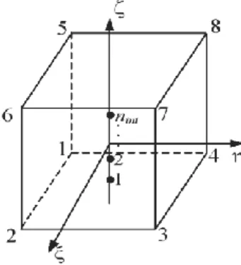
SHB8PS is an eight-node, isoparametric hexahedral el-ement with linear interpolation. It has a set of nint
integra-tion points chosen along the thickness direcintegra-tion
in the local coordinate frame (see figure 1).Figure 1.SHB8PS reference geometry.
The spatial coordinates xi of any point in the element
are related to the nodal coordinates xiI using the classic
linear isoparametric shape functions NI, which reads
8 1 ( , , )
( , , )
i iI I iI I I x x N x N
(3)In the same way, the interpolation of the displacement field ui inside the element is given in terms of the nodal
displacements uiI by 8 1 ( , , )
( , , )
i iI I iI I I u u N u N
(4)where subscript i represents the direction of the spatial coordinates and varies from 1 to 3, while subscript I is associated with the element nodes and varies from 1 to 8.
The strain vector can be related to the nodal displace-ments by the equation
, , , , , , , , ,
ˆ
( )
x x y y z z s x y y x y z z y x z z xu
u
u
u
u
u
u
u
u
u
B d
(5)where
ˆB
is the modified discretized gradient operator (see reference [2] for further details).2.3. Stabilization and assumed strain method
The particular location of the integration points along a line generates six so-called hourglass modes. The control of the hourglass modes of the SHB8PS element is achieved by adding a stabilization component KSTAB to the element
stiffness matrix Ke. This part is drawn from the work of
Belytschko and Bindeman [3], who applied an efficient stabilization technique together with an assumed strain method. The stabilization forces are consistently derived in the same way. Moreover, the discretized gradient operator is projected onto an appropriate sub-space in order to eliminate shear and membrane locking.
The stiffness matrix
K
e can then be written using thefollowing additive decomposition:
12
ˆ
ˆ
e T e Geom STAB Geom epd
K
B C
B
K
K
K
K
(6) whereˆB
is the projection of the modified discretized gradient operatorˆB
onto an appropriate sub-space in order to eliminate locking [2]. The first term K12 is evalu-ated at the integration points asint 12 12 12 12 12 1
ˆ
ˆ
ˆ
ˆ
( ) ( )
( )
( )
( )
e T ep n T ep I I I I I Id
J
K
B C B
B
C
B
(7)In this equation,
J
( )
I is the Jacobian of the transfor-mation between the reference and the current configura-tions,
( )
I is the corresponding weight, whileep
σ C
ε is the elastic–plastic tangent modulus. The geometric stiffness matrix KGeom is due to the non-linear
(quadratic) part of the strain tensor and KSTAB represents
the stabilization stiffness given by
12 34 34 12 34 34
ˆ
ˆ
ˆ
ˆ
ˆ
ˆ
e e e T ep T ep STAB T epd
d
d
K
B C B
B C B
B C B
(8)In a similar way, the internal forces of the element can be written as int 12 1 12
ˆ
( ) ( )
ˆ
( ) ( )
e T STAB n STAB I I I I I int int Td
J
f
B
σ
f
f
σ
f
B
(9) wheref
STABrepresents the stabilization forces.
The stabilization terms are calculated in a co-rotational coordinate system. This leads to simplified expressions and a more effective treatment of shear locking in this frame (for more details see [2]).
3.
SIMULATION OF THE CYLINDRICAL CUP
DRAWING PROCESS WITH ANISOTROPY
The performance of the SHB8PS, implemented into Abaqus/Standard, is evaluated in this section through the cylindrical cup drawing process. This process is commonly used to study the earing evolution when anisotropic behav-ior for sheet metals is considered. All the details regarding the simulation process are taken from Yoon et al. [7]. The schematic view of the setup is shown in figure 2, while the values of the corresponding geometric parameters are given in table 1.Dd Dp rd Db t0 Blank holder Die Punch rp
Figure 2. Schematic view of cylindrical cup drawing setup. Table 1. Geometric parameters of the cup drawing process.
Punch diameter 97.46 mm Punch profile radius 12.70 mm Die opening diameter 101.48 mm
Die profile radius 12.70 mm Blank radius 158.76 mm Initial sheet thickness 1.6 mm
The material used for the simulations is the Aluminum AA2090-T3 sheet. The associated elastic–plastic material parameters are given in table 2 according to Swift’s iso-tropic hardening law [7].
Table 2. Material parameters for AA2090-T3.
E
(MPa) (MPa) K n 0 AA2090-T3 70500 0.34 646 0.227 0.025
The anisotropic plastic behavior is taken into account in this problem by considering the Hill’48 quadratic aniso-tropic yield criterion [8]. To this end, the three values of Lankford’s coefficients r0, r45 and r90, required to identify
Hill’s coefficients, are given in table 3 [7].
Table 3. r-values for AA2090-T3 Aluminum sheet.
r0 r45 r90
AA2090-T3 0.2115 1.5769 0.6923
Due to the problem symmetry, only a quarter of the sheet is analyzed. For the SHB8PS, a mesh of 800 solid– shell elements is considered, in which only a single ele-ment is used along the sheet thickness, but with a varying number of through-thickness integration points (figure 3).
Figure 3. Initial in-plane mesh of the blank.
The tools are modeled as discrete rigid bodies. The Coulomb coefficient of friction between the tools and the blank is assumed to be equal to 0.1.A blank holder force of 22.2 kN is applied during the forming process. These process parameters correspond to the experimental condi-tions given by [7].
In order to evaluate the performance of the SHB8PS solid–shell element, the simulated earing profiles and the thickness strain distributions along the rolling and trans-verse directions of the cup drawing are analyzed and com-pared to the experimental results reported in [7]. In addi-tion, the results are compared to those obtained by the Abaqus (C3D8) element using several layers across the thickness. The C3D8 is an eight-node hexahedral element with full integration. Figure 4 shows the final drawn cup of the aluminum sheet. It can be seen that the SHB8PS ele-ment, combined with the Hill’48 quadratic anisotropic yield criterion, is able to predict the typical four ears in the cylindrical cup drawing process.
(a) (b)
Figure 4. Equivalent plastic strain distribution at the final punch displacement using the SHB8PS element: a) Full model of the final cup, b) a quarter model of the final cup.
Figure 5 depicts the predicted cup height profiles, for the quarter model, obtained with the SHB8PS using a single element layer with several integration points along the thickness together with the experimental measurements given in [7]. At first, one can observe that in the whole the results are in good agreement with experiments, with the predicted cup heights slightly underestimated at 0° and 90° from rolling direction. In particular, the predicted cup heights are closer to the experiments in the range around the experimental peak value at 50° from rolling direction. Further, the sensitivity to the number of integration points through the thickness is investigated in figure 5. It can be seen that the simulations of the cup height profiles con-verge starting from two integration points through the thickness for the SHB8PS element. This interesting result demonstrates the capability of the SHB8PS element to accurately describe various through-thickness phenomena using a single layer with a few integration points.
In figure 6, the predicted cup height profiles given by the SHB8PS element with two integration points are com-pared to those obtained using the C3D8 element with sev-eral layers of elements through the thickness. These results show that convergence for the C3D8 element is reached starting from two layers, which increases twice the total number of elements, as compared to the SHB8PS element mesh, since the in-plane mesh is exactly the same for both elements. In addition, the cup height profiles yielded by the SHB8PS element are the closest to experiments for almost the entire range of angles from rolling direction.
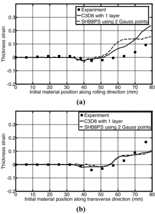
The thickness strain distribution along the rolling and transverse directions at the end of the forming process is also analyzed in this problem. Figure 7 compares the pre-dicted and measured thickness strain in both directions. For the SHB8PS element, only the results using two inte-gration points are plotted here because of the fast
conver-gence of this element. In order to have the same number of through-thickness integration points as SHB8PS element, a single layer of C3D8 element is used. In the rolling direc-tion (see figure 7(a)), the results are in good agreement with experiments from the centre of sheet to the initial position of 50 mm. Beyond this position, the simulated results differ from the experiments for both elements. In the transverse direction, the thickness strain distributions for both elements are very close to each other and in good agreement with experiments from the centre of sheet to the initial position of 70 mm (see figure 7(b)).
0 10 20 30 40 50 60 70 80 90 35 40 45 50 55
Angle from rolling (deg.)
Cu p hei ght (m m ) Experiment
SHB8PS using 2 Gauss points SHB8PS using 3 Gauss points SHB8PS using 5 Gauss points SHB8PS using 7 Gauss points
Figure 5. Cup height profiles: influence of the number of through-thickness integration points for the SHB8PS.
0 10 20 30 40 50 60 70 80 90 35 40 45 50 55
Angle from rolling (deg.)
Cu p hei ght (mm) Experiment C3D8 with 1 layer C3D8 with 2 layers C3D8 with 3 layers C3D8 with 4 layers SHB8PS using 2 Gauss points
Figure 6. Comparison of the predicted results, using SHB8PS and C3D8 FE, and measured cup height profiles.
4.
CONCLUSIONS
In this work, the performance of the SHB8PS solid– shell element has been successfully evaluated in the con-text of sheet metal forming applications involving various sources of non-linearities (geometric, material, contact …) as well as anisotropic plastic behavior at large strain. To this end, this element technology has been implemented into the implicit finite element code Abaqus via the UEL subroutine. Its formulation has been only briefly summa-rized in this paper; its main features consist of the physical stabilization of the hourglass patterns caused by the re-duced integration, and the assumed strain method aiming at alleviating locking phenomena. Cylindrical cup drawing simulations have been performed for AA2090-T3 Alumi-num alloy sheet. At equivalent mesh density, yet with much fewer integration points than the Abaqus C3D8 solid element, the earing profiles obtained with the SHB8PS element are in better agreement with experiments. For the thickness strain distributions, the results are in good
agreement with experiments in the whole, however some improvement can be expected by adopting finer descrip-tions for the plastic anisotropy of the considered material. Indeed, advanced non-quadratic anisotropic yield functions that are more suitable to aluminum alloys can contribute to better outcomes [7, 9]. 0 10 20 30 40 50 60 70 80 -0.2 -0.1 0 0.1 0.2 0.3
Initial material position along rolling direction (mm)
Thi ck nes s s trai n Experiment C3D8 with 1 layer
SHB8PS using 2 Gauss points
(a) 0 10 20 30 40 50 60 70 80 -0.2 -0.1 0 0.1 0.2 0.3
Initial material position along transverse direction (mm)
Thi ck nes s s trai n Experiment C3D8 with 1 layer
SHB8PS using 2 Gauss points
(b)
Figure 7. Comparison of predicted and measured thick-ness strain: (a) rolling direction, (b) transverse direction.
5.
REFERENCES
[1] F. Abed-Meraim, A. Combescure: SHB8PS – a new adaptive, assumed-strain continuum mechanics shell element for impact analysis, Computers and Structures, 80 (2002), 791-803.
[2] F. Abed-Meraim, A. Combescure: An improved assumed strain solid–shell element formulation with physical stabilization for ge-ometric non-linear applications and elastic–plastic stability analy-sis, International Journal for Numerical Methods in Engineering, 80 (2009), 1640-1686.
[3] T. Belytschko, L. Bindeman: Assumed strain stabilization of the eight node hexahedral element, Computer Methods in Applied Me-chanics and Engineering, 105 (1993), 225-260.
[4] A. Salahouelhadj, F. Abed-Meraim, H. Chalal, T. Balan: Applica-tion of the continuum shell finite element SHB8PS to sheet forming simulation using an extended large strain anisotropic elastic–plastic formulation, Archive of Applied Mechanics, (2012), in press. [5] J. Fish, T. Belytschko: Elements with embedded localization zones
for large deformation problems, Computers and Structures, 30 (1988), 247-256.
[6] J.C. Simo, T.J.R. Hughes: On the variational foundations of as-sumed strain methods, Journal of Applied Mechanics, 53 (1986), 51-54.
[7] J.W. Yoon, F. Barlat, K. Chung, F. Pourboghrat, D.Y. Yang: Earing predictions based on asymmetric nonquadratic yield function, In-ternational Journal of Plasticity, 16 (2000), 1075-1104.
[8] R. Hill: A theory of the yielding and plastic flow of anisotropic metals, Proceedings of the Royal Society of London A, 193 (1948), 281-297.
[9] F. Barlat, H. Aretz, J.W. Yoon, M.E. Karabin, J.C. Brem, R.E. Dick: Linear transformation-based anisotropic yield functions, In-ternational Journal of Plasticity, 21 (2005), 1009-1039.