HAL Id: hal-02465659
https://hal.archives-ouvertes.fr/hal-02465659
Submitted on 4 Feb 2020
HAL is a multi-disciplinary open access
archive for the deposit and dissemination of
sci-entific research documents, whether they are
pub-lished or not. The documents may come from
teaching and research institutions in France or
abroad, or from public or private research centers.
L’archive ouverte pluridisciplinaire HAL, est
destinée au dépôt et à la diffusion de documents
scientifiques de niveau recherche, publiés ou non,
émanant des établissements d’enseignement et de
recherche français ou étrangers, des laboratoires
publics ou privés.
New architecture for high data rate turbo decoding of
product codes
Javier Cuevas Ordaz, Patrick Adde, Sylvie Kerouedan, Ramesh Pyndiah
To cite this version:
Javier Cuevas Ordaz, Patrick Adde, Sylvie Kerouedan, Ramesh Pyndiah. New architecture for high
data rate turbo decoding of product codes. GLOBECOM 2002 : IEEE global telecommunications
con-ference, Nov 2002, Taipei, Taiwan. pp.1363 - 1367, �10.1109/GLOCOM.2002.1188421�. �hal-02465659�
NEW ARCHITECTURE for HIGH DATA RATE
TURBO DECODING of PRODUCT CODES
Javier CUEVAS, Patrick ADDE, Sylvie KEROUEDAN a nd Ramesh PYNDIAH ENST Bretagne, Technopôle Brest Iroise, BP 832, 29285 BREST Ced ex, France.
E-mail: Javier .Cuevas(a).enst-bretagne. fr, Pa [email protected], Sylvie. [email protected] and B-amesh.Pyndiah@Enst-B retagne. fr
Tel:+332 29001091
Abstract - This paper presents a new circuit architecture for turbo decoding, which achieves very high data rates when using product codes as error correcting codes. Although this architecture is independent of the elementary code (convolutional or block) used and of the corresponding decoding algorithms, we focus here on the case of product codes. This innovative circuit architecture stores several data at the same address and performs parallel decoding to increase the data rate. It is able to process several data simultaneously with one memory (classkal designs require m memories); its latency decreases when the amount of data processed simultaneously is large. We present results on block turbo decoder designs of 2-data, 4-data and 8-data decoders (where 2, 4 and 8 are the number of data symbols processed simultaneously). For each decoder circuit, the latency is decreased, the area of the processing uni! is increased by a factor m and the critical path and memory si�e are constant (the data rate is increased by m2 if
we have m parallel decoders).
1. INTRODUCrJON
The concept of turbo codes was introduced by C. Berrou [1 J in 1993. The coding scheme is based on the parallel concatenation of two recursive systematic convolutional codes separated by a non-uniform interleaver. Decoding uses an iterative process with soft input-soft output (SISO) decoders. This principle, known as convolutional turbo codes (CTC), has exceptional perfonnance close to the Shannon limit.
An alternative solution to CTCs are block turbo codes (BTC) proposed in 1994 by R. Pyndiah [2][3](4]. This coding scheme uses the series concatenation of block codes (product codes, introduced in 1954 by P. Elias [5]) and the iterative process is also obtained using SISO elementary decoders. Series concatenation guarantees a large minimum Harnming distance (9, 16, 24, 36 and higher) even for relatively small data blocks. The extrinsic information which has a significant role in turbo decoding is used not only for data bits but also for redundancy bits at each iteration.
The object of this paper is to recall the basic principles of decoding for product codes: their construction and the principles of turbo decoding. Then we present hîgh data rate
Fax :+3329800 !l 84
turbo decoding architectures, the classical and an innovative approach. Finally, we present the latest results on black turbo decoder design for high data rates based on massive parallel decoding.
Il. BASIC PRINCIPLES FOR BTC DECO DING
In this section we present the concept of product codes, their construction and the principle of the dccoding algorithm. 1. Construction of Product codes
We consider two systematic linear block codes C1 with parameters (n1,k1,Ô1) and C2 with parameters (n2,k2,Ô:1), where
n;, k; and Ôi (i=l,2) stand for codeword length, number of infonnation bits, and minimum Hamming distance, respectively. The product code is presented in the form of a matrix C with n1 rows and n2 columns where:
1.- the binary information is rcprcscnted by a sub-matrix M of k1 rows and k2 columns
2.- the k1 rows of the matrix Mare coded by the code C2•
3.- the n2 columns of the matrix C are coded by the code Ci.
",
l
k,k, Information symbo-ls
•,
1
Checks on çQ-lt).IJ)Jls +-Figure J : Construction of product code P == C1 @ C,. The pararneters of the resulting product code Pare n= n,x n2,
1.- k1x k2,
�o
1x8i and code rate R is given by R=R1xR2,where R; is the code rate of code C; illustrated in Figure l. If the code C1 is linear and systematic, then (n1-kJ rows built by C1 are words of the code C2 and can thus be decoded like the
k1 füst rowi;. In this case, the product code is characterized by
n1 words of code of C;i along rows, and by rr1 words of code
of CI along the columns. The codes C1 and C2 can be obtained
from elementary convolutional codes or linear block codes (extended BCH code).
2. Principles of turbo decoding
The turbo decoding of product codes uses an iterative decoding structure consisting of cascaded soft input•soft output decoders for the rows and columns of matrix C [6][2]. Between each decoding, a reconstruction of the matrix is essential to recover the codewords when decoding is completed, as illustrated in Figure 2.
Reccplion of data Re,;onstruc:tion of the matrix Dccoding of oolumns ( half-iteration) Dccoding of rows ( half-i�ion) Dccoding of columns ( half-iteration) Reconscruction of the matrix
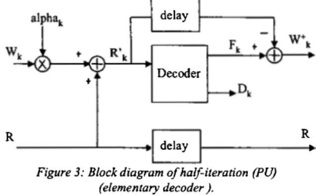
Fii;ure 2: lterative process of turbo decoding. In general, the data processing between two half-iterations (a row and column decoding) is illustrated in Figure 3. Consider R,. the information received ftom the channel, R'k the
information that cornes from the previous half-iteration and R\+ is the information sent to the following half-iteration.
The output of each half-iteration is equal to � plus the extrinsic infonnation, Wk, multiplied by alpha. This extrinsic
information corresponds to the contribution of the previous decoder to the data bits. It is obtained by the difference between the soft output Fk and the soft input ofthis decoder. alpha and fJ are constants varying with the current half iteration.
Theo we consider the SISO decoder as a block with � and Wk as inputs, delivering �· et
wt
with a latency L (delay to perform the decoding algorithm). In the following we call the SISO elementary decoder the Processing Unit (PU).In the PU, the different steps of the algorithm are given below [7][8];
1- Search for the p least reliable binary symbols of [R.k]; their positions are called 11,12, ... ,Ip and the reliabilities of these
symbols are MF1= lr11I, MF2=
lr12
l, ... ,MF p= lr1pj2- Generate î test vectors [T� QE {1, ... ;î} which are a combination of elementary test vectors [Tj] having "1" in position Ij and "O" elsewhere.
3- For each test vector [T�, compute:
[ZQ]= (T� Ef) sign ([R'iJ+l)/2).
4- Decode (ZQ] using the Berlekamp algorithm (result [yQ]). 5- For each vector [yQ], compute the square Euclidean
distance MvQ between [Rk] and [yQ].
6- Select codeword ·[Y°] having the minimal distance with [R'k]. Theo [D] = [Y'1] is the result ofbinary decoding.
7- Select the closest test vectors of[Dl, called competitors. 8- Compute the reliability for each element di of [D]. 9- Compute the extrinsic information.
R
delay
+ Decoder
delay
Figure 3: Black diagram of half-ileration (PU) (elementary decoder ).
R Il
The hardware of the PU is split into five parts as illustrated in Figure 4:
1- the input sequential part concems ail the functions where calculations are perfonned at the rhythm of the input symbols (a counter used for the timing of the elementary decoder, the parity, the syndrome and the five Jeast reliable binary symbols of the input sequence).
2- the algebraic decoding part determines · the optimum codeword for a given input binary vector.
3- the selection part selects the maximum likelihood codeword (that is, the word at minimum distance of IR'kl)
and the concurrent codewords when there is at least one (we choose to store a maximum ofthree concurrent code words). 4- the output sequential part computes the extrinsic information where calculations are performed at the same rate as the output symbols.
5- two storage elements are divided into three RAMs in order
perform some operations in parallel (writing, computing, reading).
Binary
Input Dccoding �lection
$equcnlial patl Ou:tput Sequcntial RAM patl R· R R' • k R'k Rie Delay
�·
Figure 4: Black diagram of a ha/f-iteration decoder
lll. ARCHITECTURES FOR HIGH RATES
In this section we present both the classical and the new architectures for the turbo decoding of product codes at very high data rates.
1. Classical approach
The cri tical path in turbo decoders is located in the Processing Units PU. For a given technology, we will consider that the PU works at a maximum frequency Frumait,
which is given by the maximum operating frequency of the elementary decoders. If the frequency Fra1e is higher, it will be
necessary to duplicate the turbo decoders to process a greater number of data at the same time, as illustrated in Figure 5.
Turbo decoder 1 Turbo decoder 2
Turbo decoder m
Figure 5: One architecture for high rates (F "'" = m. F rummJ
Product codes possess the property that codewords along the rows (or the columns) in the initial matrix C can be decoded independently. Thus, we can decode the rows (or columns) by duplicating the number of elementary decoders of the C1 code (or C2) as shown in Figure 6.
Whole memory of n1 x n2 Symbols on q bits Elementary decoder 1 Elementary decoder 2 Elementary decoder n1
Figure 6: Architecture of high rate decoding severai rows at the same time.
We can process a maximum number of n1 (or ni) words provided the access to the memory, in reading or in writing, takes place at different instants .(several memory points of a matrix cannot be read or written at the same time, unless using "multi-ports" RAM). It is possible to gain a factor n1
(or n2) in the ratio F,.1.lfrumax by processing n1 (or n2) binary
elements simultaneously. The disadvantage of this
architecture is that the memory must operate at a frequency equal to m.FT=, where· m is the number of decoders in
parallel.
2. Innovative approach
To increase the data rate, we store several data at the same address. However, it is necessary to process these data by row and by column. At this address the data are adjacent for reading (or writing), by row and column. Let us consider two adjacent rows and two adjacent columns of the initial matrix, as illustrated in Figure 7.
j j+l 1
i+I 1--����-1-�l---1
Figure 7: Representation of data in the new matrix
The 4 data (i, j), (i, j+ 1 ), (i+ 1, j) and (i+ 1, j+ 1) constitute a word of the new rnatrix that has 4 limes fewer addresses (I, J).
Ifn1 and n2 are even,
then if
if l::Sl:S111/2, ISJSn/2,
i=2*1-I. j=2*J-I. To decode the rows, the data (i, j), (i, j+ 1) are processed by PUI, (i+I, j) and (i+I, j+I) by PU2. To decode the columns, the data (i, j), (i+ 1, j) are processed by PUI and (i, j+ !), (i+ 1, j+ 1 ) by PU2. The reading ( or writing) data rate is 4 times faster than previously, as illustrated in Figure 8.
Addresses 1 3 5 7
...
1 3 5 Addresse 1 3 5 s J l 3 5 7 ... ) PUI column (1,1) (2,1) 2 4 6 8 " ' " l 5 .. 2 4 6 8 ... l 3 5 .. PU2oolunm (2,1)(2,2) PUI row -PU2 row (1,1) (1,2) (2,1) (2,2)Figure 8: Example of memory splitting into 4 parts.
In short, if a word of the new matrix contains m data by row and m data by column, the reading (or writing) data rate is m2
times faster than the reading (or writing) data rate of m PU using the classical approach. This organization of data does not require either particular memory architectures, or higher speed.
IV. TOWARDS THE IMPLEMENTATION OF A HIGH RATE TURBO DECODER.
By using the method described in section III, we can increase the data rate of BTC by a factor m if we use m parallel decoders for the rows or columns. One of the other advantages of this solution is that m data bits are read simultaneously from the memory for each of the rows (or columns). We shall now use this property to increase the data rate of the PU by processing m data bits per clock period. 1. Previous implementation: one-data-decoder
In our study, the reference circuit is the one-data-decoder implemented in 2000 [9]. This prototype consists of a one chip turbo decoder of BCH(32,26,4) ® BCH(32,26,4). The algorithm was implemented with 5 quantization levels, 16 test vectors and 3 competitors. With 7.5 iterations, the decoder achieves results close to theoretical limit as described in [9] [ 1 O]. The decoding of a word is split into 3 phases: reception, processing and emission. Each phase requires 32 clock periods and the latency of the decoder is 64 clock periods. 2. New implementation
For the new architecture, we shall use the same product code BCH(32,26,4) ® BCH(32,26,4) and the same algorithm, but now we process m (2, 4 or 8) data simultaneously using 32/m dock periods (16, 8 and 4 respectively) for the decoding. The design ofthese 3 elementary decoders (PU) is an extension of the one-data-decoder. So we were able to compare the ditferent solutions. The validation started with software simulations (C program), then VHDL functional simulations whîch were compared to the one-data-decoder simulations. The synthesis of the design was performed on a Synopsys Design Compiler for each decoder.
...,
Binary -Input Dccoding Sdc:clion1
Sequentîal part Output1
Sequenüal RAM RAM RI-8'J f-t, part R' Rt
î
Rl-8'k + -1 RI-8 Delay Rl-8 +Figure 9: Block diagram of a half-iteration decoder
processing 8 data simultaneous/y.
The design of each decoder is based on the concept of parallel decoding architecture. In figure 9 the 8-data-decoder architecture is illustrated.
The results summarized in Table 1 show the complexity of each PU. The area evaluation for each decoder is derived from the synthesis of the diagram in figure 9 with 2, 4 and 8 data, in the ST Microelectronics CMOS 0.18 µm target library. Table 1 shows the complexity in gate unit and their critical path for the different decoders.
Number of gates Critical path excluding RAM
!-data PU 5400 11.5 ns
2-data PU 6750 10.5 ns
4-data PU 11000 12.5 ns
8-data PU 18800 11.5 ns
Table 1: The area and its critical path for the different decoders.
The results obtained show that the critical path is similar for the four Processing Units. From then on, we synthesized the PU with FTumax
=
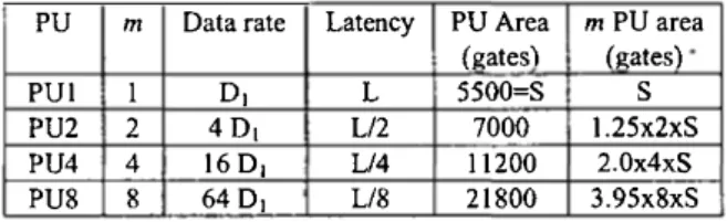
IOOMhz (clock period = lOns). The mainresults are shown in table 2. The 1-data PU called PUI is the reference, PU2 , PU4 and PU8 are respectively 2-data PU, 4-data PU and 8-4-data PU.
PU m Data rate Latency PU Area m PU area {gates) faates)
PUI 1 D1 L 5500=S
s
PU2 2 4D1 L/2 7000 l.25x2xS
PU4 4 16 D1 L/4 11200 2.0x4xS
PU8 8 64D, L/8 21800 3.95x8xS Table 2: Main characteristics of different decoders. The latency of the PUm is divided by m. The data rate of PUm is increased by m and the necessary area of m PUm is approximately increased by m.m/2. The size of the memory (RAM), used to store (RJ and [WJ, is the same in the ail cases.
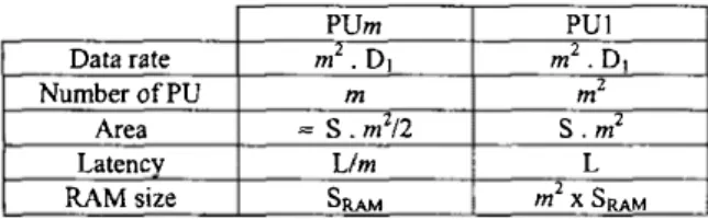
Thus, with PU8, the data rate is 6.4 Gbits/s and the area is multiplied by 32. To obtain the same data rate with PUI, we must use 64 PUI and 64 RAMs. In table 3, we compare the characteristics of the decoder using PUm with the decoder using PUI and operating at m2 D1.
PUm PUI
Data rate m2• D1 m2 .D,
NumberofPU m mz
Area =S. m2/2 S. m2
Latencv
Llm
LRAMsize SRAM m2x SRAM
Table 3: Comparison of characteristics of the decoder usiilg PUmwith the decoderusing PUI, and operating at m2 D1.
V. CONCLUSION
In this paper, we have proposed a new architecture for implementing very high data rate turbo decoders. This solution can be applied to convolutiona! codes and linear black codes. We have used the concept ofpara!lel processing architectures as well as that of parallel data storage {at the same address) in order to increase the decoding speed. To illustrate the concept we have considered the example of a
turbo decoder for product code
BCH(32,26,4)®BCH(32,26,4). The basic processing unit (row or colurnn decoding) has the following characteristics: 5 quantization bits, 16 test vectors and 3 competitors and previous results have already shown that it is very efficient and can achieve near asymptotic perfonnance [6][ 11 ). It requires 32 clock periods for decoding a code word (data rate equa!s clock rate) and the latency is of 64 clock periods. By using m decoders (or Processing Units: PU) processing m bits simultaneously with the new solution proposed in this paper, we have shown that the overall data rate of the turbo decoder can be increased by a factor m2 and that the latency is divided by a factor m. The overall area of the m processing units is increased by a factor m2/2 while that of the memory is constant. Note that the critical path in the processing llllits is nearly constant for the values of m considered here (2,4 and 8). To increase the data rate of a turbo decoder by duplicatinj decoders (classical solution) by a factor m2 we must use m
turbo decoders in parallel combined with a demultiplexer. The latency is not modified, the total area of the processing units is multiplied by m2 and furthermore, the total area of the memory is also multiplied by
m
2• Thus the new solutionproposed here saves 50% in tenns of the total area of the processing units. But what is even more important is that the new solution divides the required memory area by a factor m1. For large turbo codes (usually high code rate product codes) the memory area can be rnuch bigger than that of the processing unit and thus brin,& a tremendous saving on memory area.
By considering a clock rate of l 00 MHz with m=8, the turbo
decoder can achieve a data rate of 6.4 Gbit/s with cascaded decoders. By performing 4 iterations with the same turbo
decoder ( 4 row and 4 column decoding) the decoder can achieve a data rate of 800 Mbit/s, which is to our knowledge the highest data rate achieved with turbo codes today. These results open the way to numerous applications in optical transmission, data storage and many others.
REFERENCES
[!] C. Berrou, A. Glavieux and P. Thitimajshima, "Near Shannon limit error-correcting coding and decoding : Turbo codes (1), "IEEE I11t. Conf 011 Comm. !CC' 91, vol 2/3, May 1993, pp. 1064-1071.
[2] R. Pyndiah, A.Glavieux, A. Picart and S.Jacq, "Near optimum decoding of product codes, "in proc. of IEEE
GLOBECOM '94 Co11/ere11ce, vol. 1/3, Nov.- Dec. 1994, San
Francisco, pp. 339-343 .
[3) R. Pyndiah, "Near optimum decoding of product codes
Block Turbo Codes" IEEE Trans. 011 Comm., vol 46, n° 8, August 1998, pp. 1003-1010.
[4] R. Pyndiah, "Iterative decoding of product codes : black turbo code," I11ternatio11al Symposium 011 turbo codes and
related topics, Brest, Sept. 1997, pp. 71-79.
[S] P. Elias, "Error-free coding,"
IRE
Trans. 011 Inf Theory,vol. IT-4, pp. 29-37, Sept. 1954.
[6] D. Chase, " A class of algorithms for decoding block codes with channel measurement information," IEEE Trans.
lnform. Theory, vol IT-18, Jan. 1972, pp 170-182.
[7] P. Adde, R. Pyndiah, O. Raoul, " Performance and complexity of block turbo decoder circuits ", Thircl
International Conference 011 Electronics, Circuits and System
ICECS'96, 13-16 October 1996, Rodos, Greece, pp. 172-175. [8J P. Adde, R. Pyndiah, O. Raoul and J.R. Inisan, "Block turbo decoder design," Imemational Symposium 011 turbo
codes and related topics, Brest, Sept. 1997, pp.166-169.
[9] S. Kerouédan and P. Adde, "lmplementation of a Block Turbo Coder on a single chip" 2nd lntemational Symposium
on Turbo Codes and Relared Topics, Brest, France, 2000.
[l OJ S. Kerouédan, P. Adde, and R. Pyndiah "How we implemented Block Turbo Codes?", A1111a/s of
te/ecommu11icatio11s, 56, n° 7-8, 2001, pp 447-454.
[11) P. Adde, R. Pyndiah and F. Buda "Design and performance of a product code turbo encoding-decoding prototype" A1111a/s of telecommunications, 54, n° 3-4, 1999,
pp 214-219.
[12] S. Kerouédan, P. Adde and P. Feny "Comparaison per fonnance/complexité de décodeurs de codes BCH utilisés en turbo-décodage", Gretsi' 99, 13/17 Sept. 1999, pp. 172-175.