HAL Id: hal-02157073
https://hal.archives-ouvertes.fr/hal-02157073
Submitted on 15 Jun 2019
HAL is a multi-disciplinary open access
archive for the deposit and dissemination of
sci-entific research documents, whether they are
pub-lished or not. The documents may come from
teaching and research institutions in France or
abroad, or from public or private research centers.
L’archive ouverte pluridisciplinaire HAL, est
destinée au dépôt et à la diffusion de documents
scientifiques de niveau recherche, publiés ou non,
émanant des établissements d’enseignement et de
recherche français ou étrangers, des laboratoires
publics ou privés.
Elsa Piollet, Edith Roland Fotsing, Annie Ross, Guilhem Michon
To cite this version:
Elsa Piollet, Edith Roland Fotsing, Annie Ross, Guilhem Michon. High damping and nonlinear
vibration of sandwich beams with entangled cross-linked fibres as core material. Composites Part B:
Engineering, Elsevier, 2019, 168, pp.353-366. �10.1016/j.compositesb.2019.03.029�. �hal-02157073�
Elsa Piollet
, Edith Roland Fotsing
, Annie Ross
, Guilhem Michon
Abstract
This article investigates the use of a recently developed fibrous core material to increase vibration damping in sandwich beams. The entangled cross-linked fibre (ECF) material is made of short carbon fibres cross-linked with epoxy resin. Dry friction between fibres provides energy dissipation when the material is deformed. Previous measurements on the material are post-processed to provide a simplified viscoelastic description of the material, for an easier interpretation of subsequent structural testings. Two sandwich beams are compared with reference honeycomb beams: a sandwich beam with an ECF core, and a hybrid beam with a honeycomb core and an ECF insert. Steady-state tests are performed on both types of beams to obtain their frequency responses for different excitation levels, and the corresponding apparent loss factors are computed. The beam with a full ECF core shows an apparent loss factor more than ten times higher than the reference honeycomb beam. The hybrid sandwich beam provides an apparent loss factor four times higher than the reference honeycomb beam. All beams exhibit nonlinear softening responses consistent with a dry friction phenomenon in the material: the resonance frequencies decrease with increasing excitation amplitude, and damping increases then decreases again at very high amplitudes while remaining largely superior to that of the honeycomb beams. Transient impact testings are also presented for a qualitative comparison of the ECF and reference beams, and the ECF beams lead to shorter decay times compared to the reference beams.
Keywords
sandwich structures; core material; entangled fibres; damping; nonlinear vibration; dry friction
1 - CREPEC, École Polytechnique, Dep. Mechanical Engineering, P.O. Box 6079 Station Centre-Ville, Montréal (Québec) Canada, H3C 3A7 2 - Université de Toulouse, ICA, CNRS, ISAE-Supaero, UPS, INSA, EMAC, 10 avenue Edouard Belin, BP 54032, 31055 Toulouse, France
Elsa Piollet
1, Edith Roland Fotsing
1, Annie Ross
1, Guilhem Michon
2 RésuméCet article étudie l’utilisation d’un matériau d’âme récent pour augmenter l’amortissement vibratoire de poutres sandwichs. Le matériau à base de fibres enchevêtrées-réticulées est constitué de courtes fibres de carbone réticulées avec de la résine époxy. Le frottement sec entre les fibres conduit à une dissipation d’énergie lorsque le matériau est déformé. Des mesures antérieures sur le matériau sont post-traitées pour fournir une description viscoélastique simplifiée du matériau, afin de permettre une interprétation plus simple des essais structuraux présentés par la suite. Deux poutres sandwichs sont comparées avec des poutres de référence ayant une âme en nid d’abeille : une poutre avec une âme enchevêtrée-réticulée, et une poutre hybride avec une âme en nid d’abelle et un insert enchevêtré-réticulé. Des essais en régime établi sont réalisés pour les deux types de poutres pour obtenir leur réponse fréquentielle pour différents niveaux d’excitation, et le facteur de perte apparent est calculé. La poutre ayant une âme enchevêtrée-réticulée sur toute la longueur montre un facteur de perte apparent plus de dix fois plus élevé que la poutre de référence à âme en nid d’abeille. La poutre sandwich hybride conduit à un facteur de perte apparent quatre fois plus élevé que la poutre de référence à âme en nid d’abeille. Toutes les poutres conduisent à une réponse non-linéaire assouplissante cohérente avec le phénomène de frottement sec dans le matériau : les fréquences de résonance décroissent lorsque l’amplitude d’exctation croît, et l’amortissement croît puis décroît à nouveau à très haute amplitude, tout en restant largement supérieur à celui des poutres à âme en nid d’abeille. Des essais d’impact transitoires sont également présentés pour une comparaison qualitative des poutres enchevêtrées-réticulées avec les poutres de référence, et les poutres enchevêtrées-réticulées conduisent à un temps de décroissance plus court que celui des poutres de référence.
Mots-clés
structures sandwichs; matériau d’âme; fibres enchevêtrées; amortissement; vibration non-linéaire; frottement sec
1 - CREPEC, École Polytechnique, Dép. génie mécanique, P.O. Box 6079 Station Centre-Ville, Montréal (Québec) Canada, H3C 3A7 2 - Université de Toulouse, ICA, CNRS, ISAE-Supaero, UPS, INSA, EMAC, 10 avenue Edouard Belin, BP 54032, 31055 Toulouse, France
1 Introduction
In aerospace applications, structures must exhibit high stiffness to weight ratios, in order to reduce fuel consumption while maintaining high mechanical strength. Sandwich structures, composed of two stiff layers separated by a lightweight layer, are widely used for this purpose. However, because of their high stiffness to weight ratios and the reduced need of joints which provide damping in metallic assemblies, composite sandwich structures tend to exhibit high levels of vibration and radiate noise. Therefore, new solutions must be investigated to increase the intrinsic damping properties of sandwich structures and dissipate vibration energy. Recent damping methods include inserting viscoelastic or piezoelectric patches on the structure [1], modifying facesheets to interleave viscoelastic layers [2,3] and modifying honeycomb cores by filling their cells with polyurethane foam [4] or with soft hollow particles [5].
Recently, Mezeix developed a new core material from entangled cross-linked fibres [6,7,8], referred to as ECF material in the present paper. The fibers are short — lengths from 10 mm to 45 mm were tested in different studies [6,7,9,10] — and can be carbon, glass or aramid fibres among others. The fibres are entangled to create a 3D random architecture, and some of the fibre-fibre contacts are cross-linked to improve the general stiffness of the material [11]. Preliminary vibration studies on sandwich beams with an ECF core showed higher damping than beams with honeycomb or foam core materials [9,12], and the sandwich beams with ECF cores were shown to exhibit nonlinear vibration responses [13]. A study on the shear deformation of ECF samples at different oscillation frequencies showed that the material dissipates energy with a behaviour typical of dry friction [10]. This behaviour was attributed to friction between the fibres, as part of the fibre-fibre contacts are not cross-linked. This is consistent with experimental and numerical studies on the static compression of entangled fibres, where friction between the fibres plays an important role [14,15]. These studies indicate that the ECF material may constitute a good candidate to reduce vibrations in sandwich structures. However, two key questions must be answered before being able to design structures with the ECF material. On one hand, the nonlinear behaviour of the material may lead to a variation in sandwich beam damping depending on the excitation level. This variation was not quantified in previous studies, as comparisons between ECF beams and reference honeycomb or foam beams were only performed at a single excitation level [9]. On the other hand, the ECF material has a higher density than honeycomb, and solutions must be investigated to integrate ECF dissipation without increasing significantly the overall mass of the structure.
The present article aims at providing quantitative data on the added damping obtained by replacing a honeycomb core by an ECF core, and at relating the ECF sandwich beam behaviour to the underlying ECF material behaviour; it also investigates a possible avenue to improve damping with a small mass increase. The novelty of the article is threefold: (1) equivalent viscoelastic properties of the ECF material are computed for an easier interpretation of the consequences of material behaviour on structural response; (2) the added damping obtained by replacing a honeycomb core by an ECF core is quantified for different excitation levels, taking into account the effect of pre-cycling the beams before testing; (3) a preliminary study of a hybrid beam with a honeycomb core and an ECF insert is presented.
The paper is structured as follows. In section2, the fabrication process of the ECF material is first described. The properties of the ECF material in shear are recalled and new equivalent viscoelastic properties are presented. Section3describes the sandwich beam specimen dimensions and materials. In section4, the experimental set-ups and procedures are detailed for the pre-cycling of the beams and their testing in steady-state and transient vibrations. Section5presents the experimental results for both the full ECF core and the hybrid configurations, showing high damping with a nonlinear behaviour. The results and future work are then discussed in section6.
2 Entangled cross-linked fibres
2.1 Material fabrication
The ECF material was fabricated following the method developed by Mezeix [7]. In the present study, carbon fibres with a 7 µm diameter and an elastic modulus of 240 GPa were used.
The fibres were bought as yarns of stranded filaments. The yarns were first cut to a length of 31 mm. The filaments of the yarns were then separated and entangled in a blower room with a 5 bar air pressure. A quantity of fibres was selected to achieve a fixed fibre volume fraction of 8.5% in the final application volume, as in [7]. As the bulk density of carbon fibres is 1770 kg/m3, this volume fraction yields a density of 150 kg/m3in the final material.
In order to increase the stiffness of the material and make it usable as a sandwich core material, some of the contacts between the fibres were then cross-linked. Epoxy resin was selected for cross-linking because of the widespread use of carbon-epoxy
prepregs in aeronautical applications. A commercial paintgun was used to project droplets of epoxy resin on the entangled fibres. The total density of the final material was 180 kg/m3including epoxy droplets.
The carbon fibres with epoxy cross-links were then introduced in a mould and polymerized at 70◦C for 8 hours. Figure1
shows a scanning electron microscopy of the material after polymerization. In this material, some of the contacts between the fibres are bonded with epoxy resin while others are free to slip. There is no matrix surrounding the fibres.
Figure 1.Scanning electron microscope observation of the cross-linked entangled carbon fibre material.
2.2 ECF material properties
The ECF material properties in vibration were recently investigated through shear deformation of small samples [10]. Shear deformation was studied because it is the main deformation of sandwich core materials [16,17]. The main results of [10] are recalled in this subsection and are extended in subsection2.3. The ECF material properties will serve as a basis to analyze sandwich beam behaviours in the following of the paper.
Two groups of two samples with dimensions 20 mm × 40 mm × 60 mm were tested in a double lap shear configuration. As the samples were handmade, testing two groups of samples with the same fibre and resin properties allowed measuring variations due to the fabrication process. A sinusoidal shear deformation γ was applied to the samples, resulting in a shear stress τ . Frequencies from 1 Hz to 80 Hz were tested, with shear strain amplitudes ranging from 5·10−4to 1·10−2. Stress-strain hysteresis loops were plotted, as shown on Fig.2for one set of samples at 20 Hz and 1 · 10−2shear strain amplitude. The study showed the following main properties, developed in the following sections:
• high dependency with respect to the deformation history, • low dependency with respect to the excitation frequency,
• high dependency with respect to the deformation amplitude (nonlinear behaviour), • some variability between samples.
2.2.1 Deformation history and pre-cycling
The ECF material has to be pre-cycled to a level higher than its highest level of expected use in order to have a stable behaviour. Indeed, when samples were deformed at a given shear strain amplitude for the first time for several cycles, their stiffness decreased while energy dissipation increased. Then, after around 40,000 cycles, the stiffness and energy dissipation stabilized. It was observed that after such cycling, any subsequent deformation with an amplitude lower than the cycling amplitude had no effect on the material properties, even after days without deformation.
2.2.2 Low frequency dependency
The material behaviour showed a very low frequency dependency in the range of frequency tested, from 1 Hz to 80 Hz: there was no frequency dependency up to 5 · 10−3shear strain amplitude, and a very low dependency for shear strain amplitudes between 5 · 10−3 and 1 · 10−2. Therefore, in the following, only the results measured at 20 Hz are presented as they are representative of the material behaviour on the whole frequency range tested, from 1 Hz to 80 Hz.
−0.01 −0.005 0 0.005 0.01 −8 −6 −4 −2 0 2 4 6 8x 10 4 Shear stress τ (Pa) Shear strain γ (m/m)
Figure 2.Measured hysteresis loop for shear strain amplitude γ0= 1 · 10−2at frequency f = 20 Hz [10]; the dashed line corresponds to
τ = G1γ with G1= 6.2 · 106Pa
2.2.3 Linear and nonlinear phenomena
From the plotted stress-strain hysteresis loops, it was observed that the material behaviour could be decomposed in a linear part and a nonlinear part: τ = G1γ + τHwith G1a constant shear modulus and τHthe hysteretic nonlinear part. The linear
behaviour was attributed to a general network stiffness due to the cross-links between fibres. A shear modulus G1= 6.0 MPa
was found on average for the samples. The nonlinear behaviour was the subject of a more thorough analysis in [10]. Fig.3
shows the hysteresis loops without the linear part (γ, τH) at 20 Hz for shear strain amplitudes ranging from 5 · 10−4to 1 · 10−2.
These hysteresis loops allowed identifying three main phenomena in the material nonlinear behaviour, highlighted in Fig.3: • dry friction: for shear strain amplitudes up to 5 · 10−3(full line), the hysteresis loops had shapes typical of a microslip
behaviour, with a smooth evolution between a “stick" configuration in which all contacts are blocked, and a “slip" configurations in which all contacts are sliding, as described by the Dahl model [18] or the Iwan model [19] for example; these shapes, along with the very low frequency dependency, pointed toward dry friction between the fibres, each fibre-fibre contact going from a stuck configuration to a sliding configuration one after the other;
• stiffening: for shear strain amplitudes higher than 5 · 10−3(dashed line), an increase in the material stiffness was observed,
which was attributed to the creation of more contacts between fibres as the material is deformed;
• overshoot: for shear strain amplitudes higher than 5 · 10−3(dashed line), the hysteresis loops exhibit an overshoot, and therefore an increase in their area which corresponds to an increase in damping; this was also attributed to the creation of contacts that would increase energy dissipation by friction.
Based on these considerations and on the generalized Dahl model [20] a full hysteresis model was derived for the ECF material, which details can be found in [10].
2.2.4 Variability between samples
The previous article also studied the variability between two sets of samples. It was observed that both sets of two samples exhibited the same general behaviour with a linear part, microslip friction, stiffening and overshoot. The overall stiffnesses of the samples were similar, with a variation of less than 5% between the identified value of G1, but a larger variability was
observed in the energy dissipation. This was attributed to the fact that the material was handmade in the laboratory, which is also the case for the present study.
stiffening overshoot
dry friction
stick
slip
Figure 3.Measured hysteresis loops (γ, τH): full line γ0≤ 5 · 10−3, dashed line γ0> 5 · 10−3, after [10]
2.3 First harmonic shear modulus and loss factor
As a complement to the hysteresis description presented in [10], a Dynamic Mechanical Analysis (DMA) is performed here to describe the material in terms of its elasticity and damping properties. DMA assumes a linear viscoelastic behaviour for the material: for a harmonic strain γ, the resulting stress τ is assumed to be harmonic as well. This hypothesis allows obtaining the complex shear modulus G∗, the shear modulus G and the loss factor η using the Fast Fourier Transform (FFT) of the stress and strain time signals. With Γ the Fourier transform of γ and T the Fourier transform of τ , the expression are the following: G∗(f ) = T (f ) Γ (f ) (1) G = < (G∗) (2) η = = (G ∗) G (3)
where f is the fundamental frequency of the signals, < (G∗) is the real part and = (G∗) is the imaginary part of G∗respectively. For a linear behaviour, both imposed strain and resulting stress have a single frequency component corresponding to the fundamental frequency, therefore the DMA description is exact. For nonlinear materials such as the ECF material, however, the DMA description is an approximation. Indeed, a harmonic shear strain will result in a shear stress containing multiple harmonics, and taking into account only the fundamental harmonic component of the shear stress may lead to a loss of information [21]. However, the classical DMA description has the advantage of being simple to apply and conveying the main properties of the material in a simple and visual manner, through quantities that are familiar to most engineering practitioners. In the present paper, it is used as a complement to the full hysteresis description, whose effect on structural response is less straightforward to predict.
Figure4shows the evolution of the obtained shear modulus and loss factor with respect to the shear strain amplitude at a 20 Hz fundamental frequency, for the set of two samples which hysteresis loops were presented in Fig.2and3. The full line corresponds to the properties after pre-cycling up to 1 · 10−2shear strain amplitude, while the dotted line corresponds to the properties obtained during the first testing before pre-cycling. It can be observed that pre-cyling up to 1 · 10−2shear strain
0
0.002
0.004
0.006
0.008
0.01
6
6.5
7
7.5
8
8.5
9
9.5
10
Shear strain γ
0(m/m)
Shear modulus (MPa)
(a)
after pre-cycling before pre-cycling0
0.002
0.004
0.006
0.008
0.01
0
0.01
0.02
0.03
0.04
0.05
0.06
0.07
Shear strain γ
0(m/m)
Loss factor
η
(b)
after pre-cycling before pre-cyclingamplitude reduced the shear modulus by about 25% from 9.9 MPa to 7.6 MPa and multiplied damping by more than four from 1.2% to 5.1% at the lowest shear strain amplitude tested (5 · 10−4).
After pre-cycling, Fig.4(a) shows that the shear modulus decreased with increasing shear strain amplitude. The shear modulus was comprised between 6.3 MPa and 7.6 MPa in the shear strain amplitude range studied. The hysteresis modeling in [10] indicated that shear modulus would tend towards 9.1 MPa at very low amplitude for this set of samples. The evolution of shear modulus is consistent with the hysteresis loop shapes shown in Fig.3which exhibited mainly softening dry friction. The stiffening behaviour shown by hysteresis loops for higher amplitudes leads to a very slight increase in shear modulus between 7.5 · 10−3and 1 · 10−2shear strain amplitude. Figure4(b) shows that the loss factor increased up to 1.5 · 10−3shear strain amplitude and then decreased with increasing amplitude, evolving between 2.8% and 6.3% in the shear strain amplitude range studied. At lower shear strain amplitudes, the loss factor would tend towards zero as indicated by the decreasing area inside the hysteresis loops. These evolutions are consistent with other works on equivalent stiffness and damping of systems with microslip [22,23].
This analysis of the ECF shear modulus and loss factor allows anticipating the following behaviour for sandwich beams with ECF core:
• sensitivity to pre-cycling with decreasing stiffness and increasing damping at a given deformation amplitude after pre-cycling;
• decreasing stiffness with increasing deformation amplitude, leading to decreasing resonance frequencies (nonlinear softening behaviour); at higher amplitude, slightly re-increasing stiffness and resonance frequencies (nonlinear stiffening behaviour);
• high damping due to dry friction, with damping first increasing and then decreasing as the deformation amplitude increases.
3 Sandwich beam specimens
3.1 Sandwich beam with ECF core
In order to assess the damping effect of the ECF material on a sandwich structure, two beams were compared: a sandwich beam with an ECF core and a sandwich beam with a Nomex honeycomb core, called honeycomb beam A in the following.
The configuration of the beams is presented on Fig.5. The length was 253 mm plus 40 mm of clamped end, and the width was 40 mm. The core had a thickness of 20 mm, while the facesheets had a thickness of 2 mm each. The beam with an ECF core can be seen mounted in clamped-free configuration on the testing set-ups in Fig.8and9.
253 mm 40 mm 24 mm Carbon facesheets Core Aluminium insert Clamped end 40 mm
Figure 5.Geometry of the sandwich beams used to test the effect of full replacement of the core by the ECF material; the core is either ECF material or Nomex honeycomb.
Each facesheet was made of seven carbon/epoxy fabric plies [0◦]7.
The Nomex honeycomb core material used as a reference had a density of 48 kg/m3and a shear modulus of 44.8 MPa in the direction of the beam main axis. This is lower than the 180 kg/m3density of the ECF material, and higher than the 6 MPa to 9 MPa shear modulus obtained after pre-cycling at 10−2shear strain amplitude [10].
To allow testing in a clamped-free configuration without deforming the beam, the core material was replaced by an aluminium part at the clamped end to locally increase the stiffness. The facesheets were then bonded to the core and aluminium end with a Redux R 609 adhesive polymerized under vacuum (1 bar) at 120◦C during 1 h.
3.2 Sandwich beam with hybrid honeycomb/ECF core
As the density of the ECF material exceeds the density of core materials such as honeycomb or foam, full replacement of the core material by the ECF material may not be desirable due to weight considerations. An option would be to use a honeycomb core with localized ECF inserts to increase damping while preserving an acceptable overall density. Therefore, preliminary tests were carried out on a hybrid sandwich beam in which only part of the core material was replaced by the ECF material.
For comparison purposes, the dimensions and materials of the beam were based on previous work on the damping of sandwich beams with viscoelastic layers [2,3]. The geometry is shown on Fig.6. The beam length was 245 mm plus 50 mm of clamped end, and the width was 30 mm. The core had a thickness of 12.7 mm, while the facesheets had a thickness of 0.8 mm each.
The facesheets were made of four plies of carbon/epoxy fabric stacked in a 0◦/45◦/45◦/0◦ sequence (the directions 90◦/-45◦/-45◦/90◦were equally represented).
A reference beam was made with Nomex honeycomb core material. At the clamped end, the honeycomb core was filled by epoxy resin loaded with hollow glass spheres to increase the stiffness. This beam is called honeycomb beam B in the following. A hybrid beam was made by inserting ECF material instead of honeycomb on a length of 40 mm near the clamped end, as illustrated on Fig.6. The inserted 30 mm×40 mm×12.7 mm fibrous sample was cut from a larger 325 mm×40 mm×12.7 mm sample. The position was chosen to maximize shear in the ECF insert, as the clamped end of a beam is a region of higher shear for all flexural modes [2]. This solution represented a 2.4% (2 grams) increase of the overall mass of the beam.
245 mm 30 mm 14.3 mm Carbon facesheets Entangled cross-linked fibres Clamped end 50 mm Honeycomb 40 mm
Figure 6.Geometry of the hybrid beam with honeycomb/fibrous core material.
In order to compare the effect of the ECF material on damping with another damping treatment, a beam with viscoelastic layer damping was also tested. Viscoelastic inserts were interleaved between two plies of the facesheet as studied in [2,3], see Fig.7(c). The viscoelastic inserts were 0.2 mm thick and covered the full length of the beam, which led to a 1.9% mass increase, close to the mass increase obtained with the ECF insert. The viscoelastic material (commercial name Smacwrap ST) has a maximal loss factor of 1.2 and a maximal shear modulus of 8.5 MPa in the [0 Hz, 600 Hz] frequency range as characterized in [2]. (c) 30 mm 14.3 mm 245 mm (b) (a) 40 mm
Figure 7.Three beams tested to assess the effect of a hybrid honeycomb/fibrous core on sandwich beam damping, top and side views: (a) reference honeycomb beam B, no damping treatment, (b) beam with hybrid honeycomb/fibrous core, and (c) beam with viscoelastic inserts
honey-comb/fibrous core and a beam damped by interleaved viscoelastic material in the facesheets.
4 Experimental procedures
4.1 Overview of the procedures
When studying linear structures, both steady-state testing and transient testing can be used to characterize the damping and resonance frequencies of the structure through its frequency response function. In the case of nonlinear structures, because the behaviour of the structure depends on the vibration level, steady-state and transient tests do not provide the same information. In this paper, both steady-state and transient tests are performed, for different purposes. On one hand, steady-state testing is performed to obtain the frequency response of the structures under different levels of excitation, and compute an apparent loss factor. On the other hand, transient testing under impact is performed in order to compare visually the response decay of different structures in the time domain. Advanced methods exist to extract quantitative data from these so-called ring-down tests when performed on nonlinear structures [24,25], but these methods are out of the scope of the present paper.
4.2 Steady-state vibration
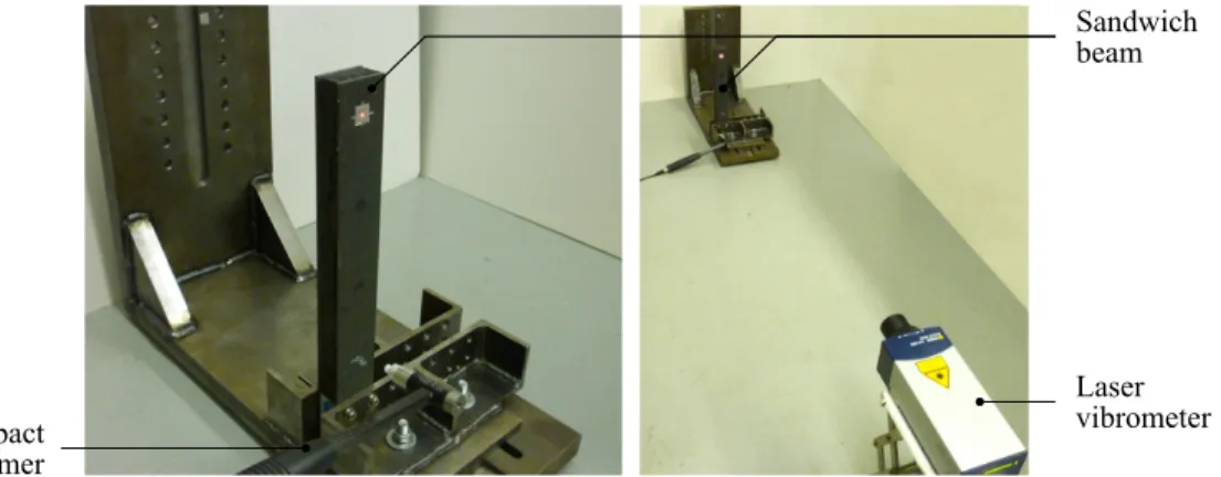
The set-up for steady-state response is illustrated on Fig.8. The beam was clamped vertically and was excited by a 10 kN shaker with a stepped sine excitation signal between 50 Hz and 2000 Hz.
Laser vibrometer Sandwich beam 10 kN shaker
Figure 8.Set-up for steady-state testing of the sandwich beams
For the full ECF beam and the corresponding reference honeycomb beam A, amplitudes ranging from 0.1 g to 10 g were applied to observe the nonlinear response. Velocity was measured at the free end of the beam, at one corner.
For the hybrid beam and the corresponding reference beams (honeycomb beam B, and honeycomb beam with viscoelastic inserts), amplitudes ranging from 0.05 g to 1 g were applied, the hybrid beam being less stiff than the beam with full ECF core as discussed in the next sections. To obtain both the frequency response and the transverse deformation, measurements were made at 33 positions along the length from the clamped end to the free end, with 2 positions across the width.
4.3 Transient vibration
The set-up for transient vibration is illustrated on Fig.9. A transient force was applied to the beam with an impact hammer with a plastic tip. The velocity response was measured with a laser vibrometer. A 1 s response was recorded with a 16,384 Hz sampling frequency, and the acquisition was triggered to start 0.015 s prior to the beginning of the impact.
The positions of impact and measurements on the beams are illustrated on Fig.10(a) and (b). For the full ECF beam, the position of impact was x = 27 mm, with x being the longitudinal position along the beam, x = 0 mm corresponding to the clamped end. The measurements were made at x = 228 mm at the middle of the width. For the hybrid beam, the position of impact was x = 20 mm and the measurements were made at x = 190 mm.
Different impact force amplitudes were applied to observe nonlinearity. For the full ECF beam and the corresponding reference honeycomb beam A, responses were measured for impact amplitudes of 10 N, 20 N, 50 N and 100 N. The two
Laser vibrometer Sandwich beam Impact hammer
Figure 9.Set-up for transient testing of the sandwich beams
228 m m 27 mm M I 190 m m 20 mm M I 0.016 0.018 Time (s) 0 5 10 15 20 Force (N) Honeycomb [20 N] Viscoelastic [20 N] Hybrid [13 N] (a) (b) (c)
Figure 10.Precisions on the set-up for transient testing: positions of impact (I) and measurement (M) for (a) the ECF beams and honeycomb beam A, (b) the hybrid beam, honeycomb beam B and beam with viscoelastic inserts; (c) example impulse signal for the hybrid beam and corresponding reference beams
reference beams for the hybrid beam were tested under 20 N and 50 N impact amplitudes. The hybrid beam itself was tested under 12.9 N and 31 N impact amplitudes, which correspond to impulse levels similar to those applied to the reference beams (same area under the force time signal), as illustrated in Fig.10(c). Indeed, as discussed further in the paper, the hybrid beam is less stiff which leads to longer impact durations.
As impacts were made with a manual impact hammer, only impacts with an amplitude within ±10% of the prescribed amplitude were kept. For each beam, 5 impacts were kept for each amplitude. The results were averaged in the frequency domain.
5 Experimental results
5.1 Full ECF core
5.1.1 Pre-cycling
As discussed in section2, the ECF material behaviour evolves with its deformation history. Therefore, it is necessary to first pre-cycle the material to the highest amplitude of interest before making any testing. In the present case, the beam with full ECF core was pre-cycled on its first bending mode on a set-up similar to the steady-state set-up described in section4.2with a 10 g acceleration. It was decided to pre-cycle the full beam on a structural mode instead of pre-cycling the core material separately before assembly for practical reasons: shear pre-cycling of the core material would have required gluing metal plates to the core material, pre-cycling, and then removing the metal plates to assemble the beam, which would have degraded the material.
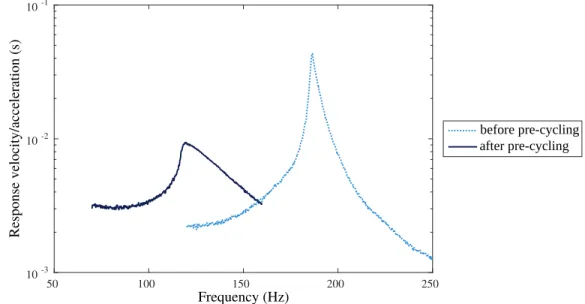
Figure11presents the effect of pre-cycling on the response of the ECF sandwich beam around its first bending mode for a given excitation level of 1 g. A first response was measured before pre-cycling, the beam behaviour being stable at the current excitation level of 1 g. Then, the beam was pre-cycled by exciting it with a 10 g excitation level until its frequency response was stable. A second response was then measured for a 1 g excitation level. For the same excitation level, Fig.11shows that the resonance frequency decreased by 36% after pre-cycling. As the resonance frequency is dependent on the mass and stiffness of the beam, this indicates a decrease in the overall stiffness of the beam, which is consistent with the decrease in shear modulus observed for small samples pre-cycled in shear (Fig.4(a)). Pre-cycling also increased energy dissipation in the beam: for the same level of excitation, the maximal response was divided by more than 4.5 (from 0.043 s to 0.0094 s) after pre-cycling. This is also consistent with the increase in loss factor observed for the small samples pre-cycled in shear (Fig.4(b)).
50 100 150 200 250 10-3 10-2 10-1 Response velocity/acceleration (s) Frequency (Hz) after pre-cycling before pre-cycling
Figure 11.Effect of pre-cycling on the frequency response of the ECF beam to a 1 g excitation
The vibration response of the reference honeycomb beam A did not exhibit any evolution under the pre-cycling procedure, which confirms that the sensitivity to pre-cycling is intrinsic to the ECF material.
The results presented in the following sections were all obtained after pre-cycling at 10 g (the highest level of excitation tested), so as to compare stabilized behaviours.
5.1.2 Steady-state response
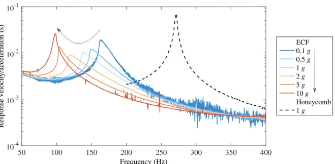
Figure12shows the velocity response of both the ECF beam (full lines) and the honeycomb beam A (dashed line) beams on their first bending modes, normalized with respect to the base acceleration.
50 100 150 200 250 300 350 400 Frequency (Hz) 10-4 10-3 10-2 10-1 Response velocity/acceleration (s) ECF 0.1 g 0.5 g 1 g 2 g 5 g 10 g Honeycomb 1 g
Figure 12.Frequency response of the ECF beam and the honeycomb beam A around their first bending mode.
It can be observed that the ECF beam exhibited a nonlinear response: for each excitation level, a different response was obtained. The response of the ECF beam was nonlinear softening: increasing excitation levels led to decreasing resonance frequencies. Figure13(a) shows that the resonance frequency decreased significantly, by 40% from 0.1 g to 10 g. The decreasing frequency with increasing excitation amplitude is consistent with the decreasing shear modulus G with increasing strain amplitude observed for small samples (Fig.4). Nonlinear softening responses are also characterized by asymmetrical resonance peaks bended towards the lower frequencies [26], which can be observed clearly up to 5 g. At 10 g, the resonance peak showed a slight bending towards the higher frequencies which indicated that stiffening started to occur. Again, this is consistent with the behaviour of small samples which exhibited stiffening in the measured hysteresis loops (Fig.3) and a slight increase in the corresponding shear modulus G (Fig.4).
The general shapes of the peaks up to 5 g are consistent with structural responses encountered in the literature for other systems featuring microslip dry friction damping, such as steel wire ropes [27,28], structures with bolted joints [29, ?] or turbine blades with underplatform dampers [30].
Contrary to the ECF beam, the reference honeycomb beam A exhibited a symmetrical resonance peak, which characterizes a linear behaviour, as shown on Figure12. Only one excitation amplitude was tested on this set-up for the honeycomb beam, however other tests were carried out beforehand to assess that the beam properties were independent of the excitation amplitude. In particular, transient tests were carried out with the set-up decribed in section4.3and showed that for impact amplitudes ranging from 10 N to 100 N, the first bending mode frequency varied by 0.07% while the loss factor varied by 3.89%. Therefore, the reference honeycomb beam behaviour was considered linear for the remainder of the study, with properties corresponding to those obtained with the measurement at 1 g.
Figure13(a) shows that the first resonance frequency of the ECF beam (◦) was always lower than that of the honeycomb beam (×) regardless of the excitation level. This can be explained by the higher density and lower stiffness of the ECF material compared to the honeycomb.
In order to evaluate the damping added by the ECF material, a linear viscoelastic approximation was applied to the steady-state responses to compare quantatively the damping level of both beams, similarly to what was done in section2.3. The half-power bandwidth method [31] was used to determine an apparent loss factor from each of the resonance peaks. The
0 2 4 6 8 10 Base acceleration (g) 0 0.02 0.04 0.06 0.08 0.1 0.12 0.14 0.16 Apparent loss f actor (b) 0 2 4 6 8 10 Base acceleration (g) 50 100 150 200 250 300 Resonance freq uency (Hz) (a) ECF Honeycomb ECF Honeycomb
Figure 13.Evolution of (a) the resonance frequency and (b) the apparent loss factor with respect to the base acceleration level for the first bending mode of the ECF beam and the honeycomb beam A
expression for the loss factor is:
η ≈ f2− f1 fr
(4)
where fris the resonance frequency and f1and f2are the two frequencies around frfor which the response level is 1/
√ 2 times the peak level. For a structure with linear viscoelastic damping, Eq. (4) provides a good approximation for small loss factors when the resonance peak considered is distant enough from other peaks to be approximated by a single degree of freedom response [31]. In the present case, the use of Eq. (4) is an approximation as the beam behaviour is nonlinear; as such, only an apparent loss factor is obtained for comparison purposes. The applicability of the half power bandwidth method to nonlinear systems is discussed in [32] and [33] among others, and is out of the scope of the present paper.
Figure13(b) shows the loss factor of the honeycomb beam and the evolution of the apparent loss factor of the ECF beam with the level of base excitation. A loss factor of 1.1% was found for the honeycomb beam under a 1 g base acceleration. At the same excitation level, an apparent loss factor of 12.9% was found for the ECF beam, more than ten times higher than for the honeycomb beam. The apparent loss factor of the ECF beam increased for increasing excitation level from 0.1 g to 2 g with a maximum of 15.9%, and then decreased for higher levels of excitation. This evolution is consistent with the increasing and decreasing loss factor found for the small samples of ECF material (see Fig.4).
Figure14shows the response of the ECF and the honeycomb core sandwich beams for a broader frequency range of 50 Hz to 2000 Hz, which covers the first four bending modes of the ECF beam and the first three bending modes of the honeycomb beam. The mode numbers are indicated in full circles for the ECF beam and dashed circles for the honeycomb beam. For each mode, the maximal response of the ECF beam was smaller than that of the honeycomb beam under the same level of excitation (1 g), which confirms the higher damping of the ECF beam. Contrary to what was observed for the first mode, damping only increased with increasing excitation level for the second and third modes on the amplitude range tested, and the behaviour was only softening. This can be explained by the fact that at higher frequencies for a given acceleration level, displacements are smaller, leading to lower levels of deformation in the core: the material did not enter the level of deformation leading to decreasing damping and then stiffening. As was the case for the first mode, the shapes of the resonance peaks are typical of microslip dry friction, which is consistent with the hypothesis of friction between the fibres inside the material.
5.1.3 Transient response
The study of the transient response provided another illustration of added damping due to the ECF material. Figure15shows the response of both beams to 10 N and 100 N impacts. The ECF beam exhibited higher damping than the honeycomb beam at
0 200 400 600 800 1000 1200 1400 1600 1800 2000 Frequency (Hz) 10-6 10-5 10-4 10-3 10-2 10-1 Response velocity/acceleration (s) ECF 0.1 g 0.5 g 1 g 2 g 5 g 10 g Honeycomb 1 g 1 1 2 2 3 4 3 ECF
modes honeycombmodes
Figure 14.Frequency response of the ECF beam and the honeycomb beam A on a larger frequency range, with corresponding mode numbers in circles
both impact amplitudes. Under a 100 N impact, a 10-fold amplitude decrease was obtained in less than 0.02 s for the ECF beam, against 0.14 s for the honeycomb beam.
In the range of 10 N to 100 N tested, damping increased with increasing amplitude. This is illustrated on Fig.16where approximate envelopes of the transient responses have been represented from local oscillation maxima to highlight the decay rate of the oscillations. Both responses have been normalized with respect to their maximal amplitude. For both 10 N and 100 N impacts, the responses decayed particularly fast during the first oscillations, and decreased more slowly at lower levels of oscillations. Moreover, the decay following a 100 N impact was much faster than following a 10 N impact. This shows than in the amplitude range tested, dissipation increases with increasing amplitude.
5.1.4 Variability
A second sandwich beam with full ECF core was tested in the same set-ups. Qualitatively similar responses were found under pre-cycling, steady-state excitation and transient excitation. Quantitatively, resonance frequencies of the first bending mode varied by about 10% under steady-state excitation after pre-cycling up to 10 g. The variations can be explained by the fact that the material was handmade; further development in the fabrication process will ensure better repeatability.
(a) 0 0.1 0.2 0.3 0.4 0.5 0.6 0.7 0.8 0.9 1 Time (s) -50 0 50 Velocity (mm .s -1 ) Honeycomb ECF (b) 0 0.1 0.2 0.3 0.4 0.5 0.6 0.7 0.8 0.9 1 Time (s) -500 0 500 Velocity (mm .s -1 ) Honeycomb ECF
0 0.05 0.1 0.15 0.2 Time (s) 0% max. amplitude V elocity (norm ialized) 100% 50% 10 N 100 N
Figure 16.Approximate envelopes of the transient responses of the ECF beam to 10 N and 100 N impacts, normalized with respect to their maximal amplitude
5.2 Hybrid core
5.2.1 Absence of pre-cycling
The hybrid beam was tested for excitation amplitudes ranging from 0.05 g to 1 g, which correspond to high deformation levels in the ECF insert as shown in the following sections. However, no pre-cycling effect was observed: the beam response was stable under repeated sollicitations at the highest excitation amplitude. This is different from what was observed for the full ECF beam. As discussed in section6, this difference can be explained by a difference in the fabrication process of the two beams: the core of the full ECF beam was made of a single specimen fabricated directly to the dimensions of the beam, while the insert used in the hybrid beam was cut from a larger specimen, which affected the mechanical properties of the sample. 5.2.2 Steady-state response
Figure17shows the steady-state responses of the hybrid beam and the reference honeycomb beam B. The behaviour was very similar to the behaviour observed for the beam with full ECF core: the hybrid beam exhibited asymmetrical peaks, decreasing resonance frequency and decreasing then increasing peak levels with peak shapes typical of microslip. This showed that the ECF insert was deformed during the beam vibration and that it played a role in the overall vibration response.
Figure18(a) shows the evolution of the first mode frequency of the hybrid beam with the base acceleration level, compared with the honeycomb beam. As for the sandwich beam with full ECF core, the frequency decreased with increasing excitation level. However, the evolution was smaller: the frequency decreased by 9% from 0.05 g to 1 g against 34% for the beam with full ECF core for a similar range of 0.5 g to 10 g (see Fig.13(a)). Moreover, the first mode frequency of the hybrid beam was significantly lower than that of the honeycomb beam. Since the added mass was low (2.35% of the original beam mass), this indicates a reduced stiffness. This is confirmed by the transverse displacement along the beam, shown on Fig.19. There is a clear change of slope at the junction between the fibrous material and the honeycomb. The higher slope in the part corresponding to the ECF insert position indicates a reduced stiffness at this specific position. This indicates that the insert is responsible for the stiffness degradation.
Figure18(b) shows the loss factor of the honeycomb beam and the evolution of the apparent loss factor of the ECF beam with the excitation level. A loss factor of 1.1% was found for the honeycomb beam at 0.1 g, which is consistent with the honeycomb beam A studied in the previous section, and with previous work on similar beams [2]. The apparent loss factor of the hybrid beam increased then decreased with increasing acceleration level, with a maximum of 4.5% at 0.1 g. While being lower than for the full ECF core (15.9%), this was still a large increase in damping compared with the reference honeycomb
100 200 300 400 500 600 700 800 Frequency (Hz) 10-5 10-4 10-3 10-2 10-1 Response velocity/acceleration (s) Honeycomb 0.5 g Hybrid 0.05 g 0.1 g 0.2 g 0.5 g 1 g 1 1 2 2 hybrid
modes honeycombmodes
Figure 17.Frequency response of the hybrid beam and the honeycomb beam B with corresponding mode numbers in circles
beam.
5.2.3 Transient response
Figure20shows the measured transient response for the hybrid beam, compared with the reference honeycomb beam B and the beam with viscoelastic inserts. All beams were impacted with a similar impulse (area under the force signal), which corresponded to different force amplitudes due to different bending stiffness. Figure20(a) shows the impact force signal. In order to see the different phases of the response, Fig.20(b) shows the full time response of the beams while Fig.20(c) shows the envelopes of the responses, zoomed on lower oscillation levels and on a reduced duration of 0.5 s. The envelopes were obtained with the envelope function of the commercial software MATLAB, which is based on the Hilbert transform.
The initial amplitude of the hybrid beam response confirms its lower bending stiffness: under similar impulse, the response of the hybrid beam was almost three times higher than the response of the other beams. However, from this higher initial amplitude, the vibration level of the hybrid beam decreased faster than the vibration level of the other beams. Around 0.055 s after the beginning of the impact, the vibration of the hybrid beam was lower than that of all the other beams, including the beam with viscoelastic inserts. This confirms that the ECF material dissipates vibration energy very efficiently. After a certain time however, as observed for the full ECF core, the damping efficiency decreased, and the viscoelastic solution became more effective: it can be observed on Figure20(c) that around 0.2 s after the impact, the vibration level of the beam with viscoelastic inserts became lower than that of the hybrid beam again.
0 0.2 0.4 0.6 0.8 1 0 0.01 0.02 0.03 0.04 0.05 0 0.2 0.4 0.6 0.8 1 130 140 150 160 170 180 190 200 210 Hybrid Honeycomb Resonance freq uency (Hz) Apparent loss f actor (a) (b)
Base acceleration (g) Base acceleration (g)
Hybrid Honeycomb
Figure 18.Evolution of (a) the resonance frequency and (b) the apparent loss factor with respect to the base acceleration level for the first bending mode of the hybrid beam and the honeycomb beam B
0 0.05 0.1 0.15 0.2 0.25 Position (m) 0 0.5 1 1.5 Transv erse displa cement (m) x 10-4 ECF insert Hybrid Honeycomb
Figure 19.Transverse displacement of the hybrid beam and honeycomb beam B under a 0.5 g base acceleration; the change in slope for the hybrid beam occurs at the junction between the ECF insert (in grey) and the honeycomb core
0
0.2
0.4
0.6
0.8
1
Time (s)
-200
-150
-100
-50
0
50
100
150
200
Honeycomb [20 N] Viscoelastic [20 N] Hybrid [13 N]0.016
0.018
Time (s)
0
5
10
15
20
Force (N)
Velocity (mm
s
-1)
.(a)
(b)
0 0.1 0.2 0.3 0.4 0.5 Time (s) -80 -60 -40 -20 0 20 40 60 80 Velocity (mm s -1 ) . Honeycomb [20 N] Viscoelastic [20 N] Hybrid [13 N] (c) lower hybrid responseFigure 20.Response to an impact: (a) impact force signal for all beams, with the same impulse level, (b) time response of the beams and (c) envelopes of the responses, zoom on lower amplitudes of vibration
6 Discussion
The results obtained for the beam with full ECF core and the hybrid beam both confirmed that using the ECF material in sandwich beams can increase significatively their level of damping compared to a Nomex honeycomb core material: maximum apparent loss factors of 15.9% and 4.5% were found for the full and partial replacement of the core, respectively, compared to 1.1% for the reference honeycomb beams.
This study gives the following elements for the design of structures including the ECF material:
• The evolution with pre-cycling gives an opportunity to “tune" the material, as the behaviour of the structure is stable for any level of sollicitation lower than the pre-cycling applied. For instance, if the level of excitation is known for a given application, a higher pre-cycling level could be applied to increase damping, if stiffness is not the main concern. On the contrary, pre-cycling could be kept as small as possible above the application level, for maximal stiffness.
• Energy dissipation in the material increases then decreases with increasing deformation levels: therefore, during the design phase, the excitation amplitude of interest and the resulting deformation in the material depending on its position in the structure should be taken into account to use the ECF material at the maximum of its capacity.
• The ECF material exhibits low damping at low deformation amplitude, which is consistent with the hypothesis that damping is coming solely from dry friction between the fibres. This is especially obvious at the end of transient responses following an impact. The comparison with viscoelastic damping in section5.2.3showed that the hybrid beam was more damped at higher vibration amplitudes, while the viscoelastic solution was more damped at lower amplitudes: this indicates that a solution that would associate friction damping and viscoelastic damping could significantly improve damping at all amplitudes.
• The nonlinear stiffness of the ECF material leads to strong variations in resonance frequencies depending on the excitation level: for the first bending mode of the beam with full ECF core between 0.1 g and 10 g, the resonance frequency decreased by as much as 40% for the first bending mode of the beam with full ECF core between 0.1 g and 10 g. Therefore, during the design phase, the nonlinear behaviour of the material has to be taken into account and considering an equivalent linear behaviour is not possible.
This study highlights the need to investigate further the evolution of the ECF properties under pre-cycling. At the macroscopic level, a quantitative relationship between the pre-cycling level and the material properties should be established. Moreover, the actual pre-cycling level of the ECF material in a structure should be known, which is not necessarily straight-foward. In the case of the full ECF beam studied in this paper, pre-cycling was made on the first bending mode of the beam, which means that the ECF material did not experience the same level of deformation at different locations along the length of the beam. Therefore, the level of pre-cycling, the final stiffness and final loss factor of the ECF material were probably different for different positions in the length of the beam: for the first bending mode of a clamped-free beam, the level of deformation is higher close to the clamped end than close to the free end, which would imply higher pre-cycling, lower stiffness and higher loss factor close to the clamped end. The actual level of pre-cycling in the length of a beam pre-cycled on a given vibration mode should be investigated. Possibilities to pre-cycle the material in an uniform way before integrating it in the sandwich structure should also be considered. At the microscopic level, the underlying phenomena leading to the property evolution under pre-cycling should be identified.
The low bending stiffness of the hybrid beam, coupled with the lack of sensitivity to pre-cycling highlighted in section5.2.1, can actually give an insight on one of the mechanisms governing the stiffness and the pre-cycling sensitivity of the ECF material. As described in sections2.2.1and5.1.1, sensitivity to pre-cycling was observed both for small samples tested in [10] and for the beam with full ECF core. The main difference between the small samples and the full ECF core on the one hand, and the insert used in the hybrid beam on the other hand, lies in their fabrication process. The small samples and the core for the full ECF beam were fabricated directly in moulds with the dimensions of the final samples to be tested, while the insert was cut from a larger sample. If ECF samples were homogeneous, cutting them would have no effect on their behaviour, but they are actually heterogeneous. Indeed, it was observed that at the end of the fabrication process, the density and organization of the fibres and resin was different on the sides of the samples compared to the interior of the samples. Fig.21(a) and (b) show small samples and the full ECF core, respectively, which exhibit similar fibre organization at their sides. Fig.21(c) shows the insert of the hybrid beam, which exhibits a different fibre organization and less resin on the side: as this sample was cut from a larger sample, this side is actually the interior of the original sample. The difference between sides and interior can be attributed to the contact of the fibres and resin against the surrounding mould during the fabrication process. While this difference has not been quantified yet, hand manipulation of the samples tends to indicate that the sides are denser and stiffer than the interior of
the samples. As the insert exhibited both a low stiffness and no sensitivity to deformation history, it is possible that these sides provide a significant part of the stiffness of the ECF samples, and that pre-cycling mainly acts on the side stiffness, possibly by breaking epoxy links in that part of the samples. This hypothesis would have to be confirmed by more analysis at the fibre-resin level.
(a) (b)
(c)
Figure 21.Consequences of the fabrication process on the sample sides: (a) small samples with adapted moulds, (b) full ECF core beam with adapted mould and (c) ECF insert in the hybrid beam cut from a larger sample.
The study on a hybrid beam was one step forward to understanding how the ECF material can be used to increase sandwich structure damping while maintaining an acceptable weight. Regarding the future use of ECF inserts in sandwich beams, the following avenues could be investigated:
• test the effect of ECF inserts in sandwich panels rather than beams to reduce the sensitivity of the structure with respect to the ECF sample stiffness;
• use small inserts fabricated in moulds at their dimension instead of cutting from larger samples;
• identify an optimal position where the shear constraint is reduced in order to limit the impact of the insertion on the overall stiffness, but where it is high enough to take advantage of the dissipative properties of the ECF material.
7 Conclusions
This paper investigated the effect of entangled cross-linked carbon fibres on the vibration response of sandwich beams. Two configurations were tested: a configuration with full ECF core, and a hybrid configuration with part ECF core and part honeycomb core.
The main result of the study lies in the large increase in damping level observed in both configurations. For the beam with full ECF core, the apparent loss factor was more than ten times higher than the loss factor of the reference honeycomb beam. The transient responses confirmed this high damping, especially under high impact levels. For the hybrid beam, an apparent loss factor four times higher than the loss factor of the reference honeycomb beam was found, whereas the added mass was only 2.4%. The initial responses to impacts showed shorter decay time than both the reference honeycomb beam and a sandwich beam with viscoelastic inserts; at the end of the transient response, however, ECF damping was lower than the reference beams.
Nonlinear stiffness and damping were observed for both types of ECF beams. The behaviour was consistent with studies on smaller ECF samples, which showed a softening behaviour attributed to dry friction between the fibres. While the samples
and structures were different in size and had different levels of pre-cycling, the general behaviours were consistent in all testings. The stiffness decreased with increasing deformation amplitude. The sandwich beam with full ECF core also exhibited a slight increase in stiffness at higher deformation amplitude, consistent with small sample behaviour. All beams tested showed increasing then decreasing energy dissipation with increasing deformation amplitude. The sandwich beam with full ECF core also exhibited decreasing overall stiffness and significantly increasing damping under pre-cycling, which was again consistent with small sample behaviour.
The hybrid beam showed a low bending stiffness with a local weakness at the position of the insert. Moreover, the hybrid beam did not exhibit any sensitivity to pre-cycling in the amplitude range tested. These observations allowed hypothesizing that the stiffness and pre-cycling sensitivity of the ECF material were related to a physical difference between the sides and the interior of ECF samples, and were therefore affected when the tested sample was cut from a larger sample.
This study opens the way to developments on the optimal use of the ECF material for vibration damping. From a material point of view, future work includes parametric investigations of the material properties depending on the fibre type, length and density as was done for static properties [7], and specific analyses of the pre-cycling sensitivity and side/interior differences highlighted in this study. Fibre parameters, pre-cycling evolution and nonlinear behaviour form a rich set of elements that could be used to tailor the ECF material to specific usages. These avenues will also enrich the existing numerical and analytical models of materials involving entangled fibres. Currently, numerical models are developed for representative volume element (RVE) of entangled fibres [15] and future work includes the integration of cross-links in such models. Improving the repeatability of the fabrication process will also constitute an important step towards the integration of the ECF material in industrial structures. On the structural side, future work includes the optimal placement of the material in sandwich structures and the integration of the material behaviour in structural simulations.
Acknowledgments
This work was made during the first author’s PhD at Institut Supérieur de l’Aéronautique et de l’Espace (Toulouse, France), and during a stay as invited researcher at Polytechnique Montreal (Canada). Université de Toulouse, Region Midi Pyrénées, Ecole Doctorale Aéronautique et Astronautique and the Natural Sciences and Engineering Research Council of Canada (NSERC) are gratefully acknowledged for their financial support.
References
[1] Treviso, A., Van Genechten, B., Mundo, D., and Tournour, M., 2015. “Damping in composite materials: Properties and
models”. Composites Part B: Engineering, 78, pp. 144–152. doi:10.1016/j.compositesb.2015.03.081.
[2] Fotsing, E. R., Sola, M., Ross, A., and Ruiz, E., 2013. “Lightweight damping of composite sandwich beams: Experimental
analysis”. Journal of Composite Materials, 47, pp. 1501–1511. doi:10.1177/0021998312449027.
[3] Horel, F., 2013. “Modélisation analytique de l’amortissement des poutres composites sandwich contenant des couches
viscoélastiques [Analytical modelling of damping in composite sandwich beams with viscoelastic layers]”. Master’s thesis, École Polytechnique de de Montréal.
[4] Li, Z., 2006. “Vibration and acoustical properties of sandwich composite materials”. PhD thesis, Auburn University. [5] Michon, G., Almajid, A., and Aridon, G., 2013. “Soft hollow particle damping identification in honeycomb structures”.
Journal of Sound and Vibration,332, pp. 536–544. doi:10.1016/j.jsv.2012.09.024.
[6] Mezeix, L., Bouvet, C., Huez, J., and Poquillon, D., 2009. “Mechanical behavior of entangled fibers and entangled
cross-linked fibers during compression”. Journal of Materials Science, 44(14), pp. 3652–3661.doi:10.1007/s10853-009-3483-y
-oai:hal-01853233-oatao:3325.
[7] Mezeix, L., Poquillon, D., and Bouvet, C., 2016. “Entangled cross-linked fibres for an application as core
mate-rial for sandwich structures - Part I: Experimental investigation”. Applied Composite Matemate-rials, 23(1), pp. 71–86.
doi:10.1007/s10443-015-9451-6-oai:hal-01847309-oatao:14146.
[8] Mezeix, L., Poquillon, D., and Bouvet, C., 2016. “Entangled cross-linked fibres for an application as core material for
sandwich structures - Part II: Analytical model”. Applied Composite Materials, 23(1), pp. 87–100. doi:10.1007/s10443-015-9450-7-oatao:14147.
[9] Shahdin, A., Mezeix, L., Bouvet, C., Morlier, J., and Gourinat, Y., 2009. “Fabrication and mechanical testing of glass
fiber entangled sandwich beams: A comparison with honeycomb and foam sandwich beams”. Composite Structures, 90, pp. 404–412. doi:10.1016/j.compstruct.2009.04.003-oai:hal-01851889-oatao:2282.
[10] Piollet, E., Poquillon, D., and Michon, G., 2016. “Dynamic hysteresis modelling of entangled cross-linked fibres in shear”.
Journal of Sound and Vibration,383, pp. 248–264. doi:10.1016/j.jsv.2016.06.023-oai:hal-01758580-oatao:19782.
[11] Masse, J.-P., and Poquillon, D., 2013. “Mechanical behavior of entangled materials with or without cross-linked fibers”.
Scripta Materialia,68, pp. 39–43.doi:10.1016/j.scriptamat.2012.05.047-oai:hal-00842769-oatao:8791.
[12] Mezeix, L., 2010. “Développement de matériaux d’âme pour structures sandwich à base de fibres enchevêtrées [Core
material development for sandwich structures with entangled fibres]”. PhD thesis, Université Paul Sabatier, Toulouse.
[13] Piollet, E., Michon, G., and Poquillon, D., 2013. “Nonlinear vibration behavior of sandwich beams with entangled fiber
core material”. In ASME 2013 International Design Engineering Technical Conferences and Computers and Information in Engineering Conference.doi:10.1115/detc2013-13010.
[14] Poquillon, D., Viguier, B., and Andrieu, E., 2005. “Experimental data about mechanical behaviour during compression
tests for various matted fibres”. Journal of Materials Science, 40, pp. 5963–5970.doi:10.1007/s10853-005-5070-1.
[15] Chatti, F., Poquillon, D., Bouvet, C., and Michon, G., 2018. “Numerical modelling of entangled carbon fibre material under
compression”. Computational Materials Science, 151, pp. 14–24.doi:10.1016/j.commatsci.2018.04.045-oai:hal-01880449 -oatao:21829.
[16] Allen, H. G., 1969. Analysis and Design of Structural Sandwich Panels.
[17] Mead, D. J., and Markus, S., 1969. “The forced vibration of a three-layer, damped sandwich beam with arbitrary boundary
conditions”. Journal of Sound and Vibration, 10, pp. 163–175.doi:10.1016/0022-460x(69)90193-x.
[18] Dahl, P. R., 1968. A solid friction model. Tech. rep., The Aerospace Corporation.doi:10.21236/ada041920.
[19] Iwan, W. D., 1961. “The dynamic response of bilinear hysteretic systems”. PhD thesis, California Institute of Technology. [20] Al Majid, A., and Dufour, R., 2002. “Formulation of a hysteretic restoring force model. application to vibration isolation”.
Nonlinear Dynamics,27, pp. 69–85.doi:10.1023/A:1017937328860.
[21] Ewoldt, R. H., Hosoi, A. E., and McKinley, G. H., 2008. “New measures for characterizing nonlinear viscoelasticity in
large amplitude oscillatory shear (LAOS)”. Journal of Rheology, 52, pp. 1427–1458.doi:10.1122/1.2970095.
[22] Al-Bender, F., and Symens, W., 2005. “Characterization of frictional hysteresis in ball-bearing guideways”. Wear, 258,
pp. 1630–1642. doi:10.1016/j.wear.2004.11.018.
[23] Laxalde, D., and Thouverez, F., 2009. “Complex non-linear modal analysis for mechanical systems: Application
to turbomachinery bladings with friction interfaces”. Journal of Sound and Vibration, 322(4-5), pp. 1009–1025.
doi:10.1016/j.jsv.2008.11.044.
[24] Sracic, M. W., Allen, M. S., and Sumali, H., 2012. “Identifying the modal properties of nonlinear structures using measured
free response time histories from a scanning laser doppler vibrometer”. In Topics in Nonlinear Dynamics, Volume 3. Springer, pp. 269–286.doi:10.1007/978-1-4614-2416-1_22.
[25] Reed, S. A., Palazotto, A. N., and Baker, W. P., 2008. “An experimental technique for the evaluation of strain dependent
material properties of hard coatings”. Shock and Vibration, 15(6), pp. 697–712. doi:10.1155/2008/853689.
[26] Nayfeh, A. H., and Mook, D. T., 2008. Nonlinear oscillations. John Wiley & Sons.
[27] Carpineto, N., Lacarbonara, W., and Vestroni, F., 2014. “Hysteretic tuned mass dampers for structural vibration mitigation”.
Journal of Sound and Vibration,333(5), pp. 1302–1318.doi:10.1016/j.jsv.2013.10.010.
[28] Barbieri, N., Barbieri, R., da Silva, R. A., Mannala, M. J., and Barbieri, L. d. S. V., 2016. “Nonlinear dynamic analysis of
wire-rope isolator and stockbridge damper”. Nonlinear Dynamics, 86(1), pp. 501–512.doi:10.1007/s11071-016-2903-1.
[29] Gaul, L., Nackenhorst, U., Willner, K., and Lenz, J., 1994. “Nonlinear vibration damping of structures with bolted joints”.
[30] Pesaresi, L., Salles, L., Jones, A., Green, J., and Schwingshackl, C., 2017. “Modelling the nonlinear behaviour of an
underplatform damper test rig for turbine applications”. Mechanical Systems and Signal Processing, 85, pp. 662–679.
doi:10.1016/j.ymssp.2016.09.007-oai:hal-01545328.
[31] Jones, D. I., 2001. Handbook of viscoelastic vibration damping. John Wiley & Sons.
[32] Davis, W. O., 2011. “Measuring quality factor from a nonlinear frequency response with jump discontinuities”. Journal of
Microelectromechanical Systems,20(4), pp. 968–975. doi:10.1109/jmems.2011.2159103.
[33] Torvik, P. J., 2011. “On estimating system damping from frequency response bandwidths”. Journal of Sound and Vibration,

![Figure 2. Measured hysteresis loop for shear strain amplitude γ 0 = 1 · 10 −2 at frequency f = 20 Hz [10]; the dashed line corresponds to τ = G 1 γ with G 1 = 6.2 · 10 6 Pa](https://thumb-eu.123doks.com/thumbv2/123doknet/12213500.316969/6.918.213.697.158.481/figure-measured-hysteresis-strain-amplitude-frequency-dashed-corresponds.webp)
![Figure 3. Measured hysteresis loops (γ, τ H ): full line γ 0 ≤ 5 · 10 −3 , dashed line γ 0 > 5 · 10 −3 , after [10]](https://thumb-eu.123doks.com/thumbv2/123doknet/12213500.316969/7.918.204.675.167.456/figure-measured-hysteresis-loops-full-line-dashed-after.webp)