HAL Id: hal-02443369
https://hal.archives-ouvertes.fr/hal-02443369
Submitted on 17 Jan 2020
HAL is a multi-disciplinary open access
archive for the deposit and dissemination of
sci-entific research documents, whether they are
pub-lished or not. The documents may come from
teaching and research institutions in France or
abroad, or from public or private research centers.
L’archive ouverte pluridisciplinaire HAL, est
destinée au dépôt et à la diffusion de documents
scientifiques de niveau recherche, publiés ou non,
émanant des établissements d’enseignement et de
recherche français ou étrangers, des laboratoires
publics ou privés.
Coupled NIRT / 3D-DIC for a FEMU identification of
the thermo-mechanical behavior of Zr-4 claddings under
simulated Reactivity Initiated Accident
T Jailin, Nicolas Tardif, J Desquines, M. Coret, M.-C Baietto, T Breville, P
Chaudet, V Georgenthum
To cite this version:
T Jailin, Nicolas Tardif, J Desquines, M. Coret, M.-C Baietto, et al.. Coupled NIRT / 3D-DIC for a
FEMU identification of the thermo-mechanical behavior of Zr-4 claddings under simulated Reactivity
Initiated Accident. 2019 SEM Annual Conference and Exposition on Experimental and Applied
Mechanics, Jun 2019, Reno, United States. �hal-02443369�
Coupled NIRT / 3D-DIC for a FEMU identification of the thermo-mechanical
behavior of Zr-4 claddings under simulated Reactivity Initiated Accident
T. Jailin
1,2, N. Tardif
2, J. Desquines
1, M. Coret
3, M.-C Baietto
2, T. Breville
4, P. Chaudet
2,
V. Georgenthum
11
Institut de Radioprotection et de Sûreté Nucléaire (IRSN), PSN-RES, Cadarache, Saint Paul lez
Durance, 13115, France
2
Université de Lyon, CNRS, INSA-LYON, LaMCoS (UMR 5259), Villeurbanne, France
3GeM (UMR 6183), École Centrale de Nantes, Nantes, France
4
ATYS Consulting Group, Herbeys, France
ABSTRACT
Nowadays, full field measurements techniques enable heterogeneous experiments to be performed without the need of averaging assumptions. The richness and the quantity of recording data obtained by these techniques led to the development of robust identification methods, such as the finite element model updating (FEMU) technique. However, it is still difficult to measure both kinematic and thermal full fields at the same location and time since the methods and the devices used to compute them are radically different. Furthermore, it may be complicated to calibrate the temperature measurement system without interfering with the metallurgical state of the sample. The present paper proposes a low-cost procedure that uses the same two CMOS cameras to compute both the 3D-surface kinematic field and the associated thermal field, by stereo-correlation and near infrared thermography, respectively. No interpolation or smoothing operation were finally necessary.
Keywords: 3D-DIC, NIRT, full field measurements, high temperatures
INTRODUCTION
The Reactivity Initiated Accident (RIA) is a design basis accident that can potentially occur in pressurized water reactors. During such accident, the fuel claddings can be subjected to intense thermo-mechanical loading conditions. Heating rates above 1000°C/s can be observed up to more than 1000°C while claddings are internally pressurized (5-100 bar). Such thermal conditions may have a strong impact on the mechanical properties of the material, especially above 800°C from which an allotropic phase transformation (hcp → bcc) is expected in Zirconium alloys. The present work aims at characterizing the thermo-mechanical behavior of as-fabricated stress relieved annealed Zircaloy-4 claddings under simulated RIA conditions. Full field measurements in experimental mechanics have been more and more used these last years for constitutive laws identification purposes. Local measurements – like strain gages or thermocouples – show their weaknesses when experiments do not enable averaging assumptions, for instance in case of localization, complex loading conditions or anisotropic behavior. The use of full field measurements techniques gives access to a large amount of data during the tests. Hence, averaging assumptions do not remain necessary anymore. It goes even further since heterogeneities in tests are now sought after to obtain richer data useful for identification purposes [1].
However, it is still difficult to measure both kinematic and thermal full fields at the same location and time since the techniques used to compute them are radically different. Digital images correlation (DIC) technique for instance requires a high random gradient in the images. Thermal full field methods, like infrared (IR) or near-infrared thermography (NIRT), need on the contrary a well-known and homogenous emissivity of the sample surface. Some authors [2, 3] used two different optical systems to compute the thermal and the kinematic fields but time and spatial interpolations remained necessary at the end to
link the two types of field. Other authors proposed to extend the DIC technique to infrared cameras [4]. However, this method needs a prior calibration step and IR cameras have often a poor spatial resolution and are relatively costly compared to standard CMOS or CCD cameras.
An additional difficulty come in case of fast thermal transients where the temperature may be difficult to measure. On the one hand, thermocouples are subjected to a potential high inertia effect under fast thermal transients. On the other hand, the speckle pattern leads to an unknown emissivity of the sample surface. Using a pyrometer is therefore complicated.
This paper proposes a low-cost procedure that uses the same two CMOS cameras to compute both 3D-surface kinematic and thermal full fields under fast thermal transients. The global stereo-correlation software UFreckles [5] was first used to compute the 3D-surface kinematic field. Then, a simple and robust procedure was developed to identify the radiometric model, used to perform the NIRT. A weak coupling between the two kinds of fields was finally achieved so that no interpolation or smoothing operation were finally required. The first section deals with the experimental setup used to perform fast thermal transient experiments. The thermal calibration procedure and the weak coupling with the 3D-DIC are detailed in the second section.
I. CREEP BALLOONING TESTS UNDER FAST THERMAL TRANSIENTS
I.1 EXPERIMENTAL SETUP
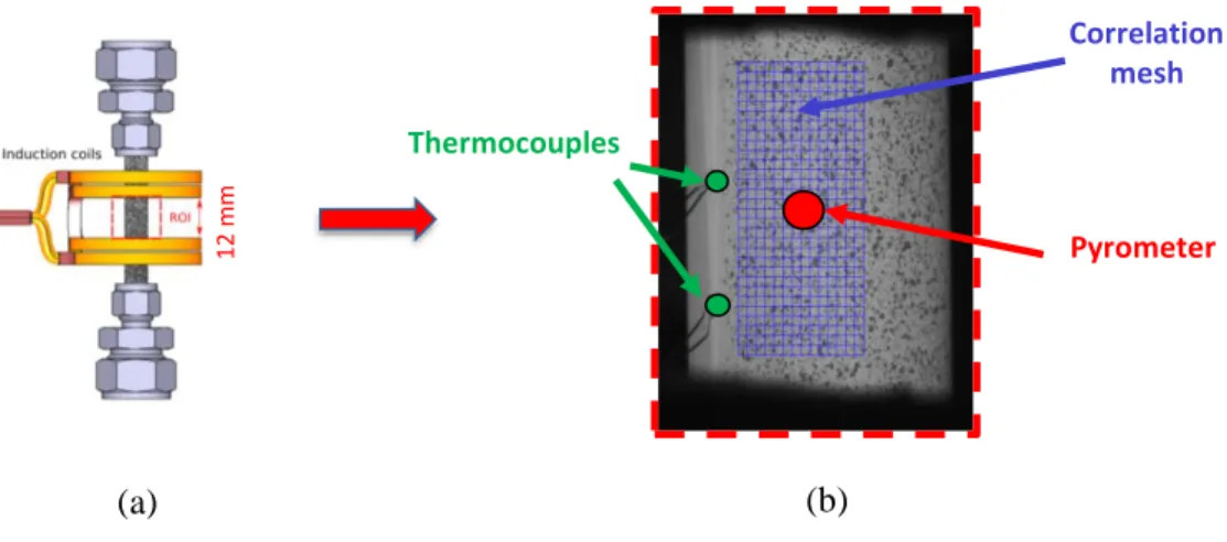
The experimental device ELLIE was used to perform creep ballooning tests on fuel rods samples with very high thermal transients. A scheme of the setup is depicted in Figure 1. The device is presented in more details in [6]. Some reminders are given in the following. The test specimens were cut from as-fabricated stress relieved annealed Zircaloy-4 claddings. They were 90mm long with an external diameter of 9.5mm and a wall-thickness of 0.57mm. In order to perform stereo-correlation measurements a black undercoating and a white speckle pattern were applied onto the samples with high-temperature paintings. Three thermocouples (type K, diameter of 79μm) were spot-welded in the region of interest (ROI) of the specimens.
The test bench was composed of a 10kN servo-hydraulic tensile machine connected to a pressurization system. Internal pressure up to 70 bar could be applied and controlled within the claddings during the whole experiments using Argon gas. An induction heating device enabled samples heating rates up to 1500°C/s up to more than 1000°C [7]. The temperature regulation was achieved using a Metis 322 pyrometer at a wavelength of λ = [1.45 – 1.65] μm. In order to avoid the oxidation of the samples at high temperatures all the experiments were performed within an enclosure where an Argon flush was setup during the tests.
Figure 1: Description of ELLIE device (a) Picture of the device [6]. (b) Scheme of the setup
I.2 EXPERIMENTAL PROCEDURE
The experimental procedure is depicted in Figure 2.a. The mechanical loading was first applied by a combination of an internal pressure 𝑃𝑖 and a compressive force 𝐹𝑧. The compressive force was calculated to compensate the pressure-induced effect as
described in Figure 2.a (with 𝑅𝑖 the inner radius of the cladding). Once the mechanical loading was stabilized, the thermal
loading was applied with heating rate around 1000°C/s up to the set point. The PID optimization led to overshoots ranging between -6 and +25°C around the target temperature. The temperature was then stabilized until the specimen burst. An example of thermal transient is shown in Figure 2.b. 3D surface kinematic and thermal fields were obtained during the whole experiment using the same two CMOS cameras by 3D-DIC and NIRT, respectively.
Figure 2: (a) Loading sequence; (b) example of a thermal transient obtained [7]
II OPTICAL FULL FIELD ACQUSITION
The application of fast thermal transients led to non-axisymmetric temperature distributions in the samples. Full field measurements techniques were used to record these loading heterogeneities. Two 12Mpx CMOS cameras recorded images of the ROI during the tests at a frequency up to 55Hz. A scheme of the setup is presented in Figure 3. The two CMOS cameras were equipped of 200mm macro optics and near infrared pass-band filters (λ = 860 +/−10nm) were mounted on the optics. The exposure time of the cameras was setup to obtain non-saturated images between -100 and +50°C around the test regulation temperature.
Figure 3: Scheme of a top view of the setup Temperature Pressure 𝐹𝑧= −𝑃𝑖. 𝜋. 𝑅𝑖2 Time Loading 990°C.s-1 t0 CMOS cameras Pyrometer
Enclosure with inert atmosphere Induction generator 30KW Zr-4 𝜃 ≈ 18° Induction coil Sample (a) (b)
II.1 KINEMATIC FULL FIELD MEASURMENTS BY STEREO-CORRELATION
The global stereo-correlation software UFreckles [5], [8], developed by J. Réthoré was used to compute the 3D-surface kinematic field. A finite element basis of Q4 elements with an element size of 35x35px2 was used to perform the images
analysis (1 px ≈ 9μm). In order to avoid chromatic aberrations at high temperature the optical system calibration was performed at low temperature before the test. This step was achieved by lighting the sample in the near infrared domain using a LED ring at the wavelength λ = 860nm. The near infrared band-pass filters mounted on the optics enabled the calibration procedure to be carried out at ambient temperature while remaining valid at high temperature.
A standard calibration, using calibration grids, could not be performed because of the device geometry and the presence of the induction coil. This step was then achieved using the well-known geometry of the claddings. Finally, the noise was estimated to be around 1μm for the in-plane displacements and about 5μm for the out-of-plane displacements.
II.2 THERMAL FULL FIELD MEASUREMENTS BY NEAR INFRARED THERMOGRAPHY (NIRT)
The NIRT technique [9] was used to compute the thermal field on the sample outer surface. This method, based on Planck’s law, links the digital level intensity 𝐼 of an image (i.e. the gray level of the pixels) to the temperature 𝑇 using a radiometric model that can be written as:
𝑇 = 𝐾1 ln (𝐾2
𝐼 + 1) (1)
Two unknown constants 𝐾1 and 𝐾2 had to be identified in this model.
A large range of temperatures had to be used in order to identify accurately this model. Only the pyrometer data could be used since the thermocouples are potentially subjected to high inertia effects under fast thermal transients. As mentioned above the speckle pattern led to an unknown emissivity onto the specimen surface. A prior emissivity identification could not be performed without interfering with the metallurgical state of the material. The pyrometer emissivity was then setup to an arbitrary value – close to its expected value – during the experiments. This emissivity value had to be corrected after the test to obtain correct pyrometer data. A third unknown to identify was then defined to be the true emissivity at the pyrometer pointing location.
On the other hand, the speckle pattern led to a heterogeneous emissivity onto the claddings. We recall that the radiometric model is based on a homogeneous and constant emissivity assumption. In order to use a single emissivity value in the radiometric model it was chosen to use only the black painting since it is the more stable to a potential oxidation of the sample. A parameter 𝑃 was then defined as the percentage of pixels corresponding to the black painting. Only the black pixels identified by this parameter were used to identify the radiometric model and compute the thermal field. A too low value of 𝑃 would result in a high impact of the noise. A too important value would lead to the use of multiple emissivities; the thermal field would then be very noisy.
Four parameters had finally to be identified to compute the thermal field: the two constants 𝐾1 and 𝐾2, the emissivity 𝜀𝑝𝑦𝑟𝑜 at
the pyrometer pointing location and the parameter 𝑃 that can be seen as a percentage threshold value defining the black painting.
Identification procedure
The pyrometer emissivity could not be identified directly using the thermocouples data since the pyrometer and the thermocouples were not located at the same position. The NIRT was then used to link the pyrometer with the thermocouples. An identification procedure of the four parameters {𝐾1, 𝐾2, 𝜀𝑝𝑦𝑟𝑜, 𝑃} is proposed below. Two objective functions are first
𝑒𝑟12= (𝑇𝑇𝐶𝑁𝐼𝑅𝑇− 𝑇𝑇𝐶)2, (2)
𝑒𝑟22= (𝑇𝑃𝑦𝑟𝑜𝑁𝐼𝑅𝑇− 𝑇𝑃𝑦𝑟𝑜)2, (3)
With:
𝑇𝑇𝐶: The temperature measured by the thermocouples,
𝑇𝑃𝑦𝑟𝑜: The temperature measured by the pyrometer,
𝑇𝑇𝐶𝑁𝐼𝑅𝑇: The temperature obtained by NIRT at the thermocouples areas (green circles in Figure 4.b),
𝑇𝑃𝑦𝑟𝑜𝑁𝐼𝑅𝑇: The temperature obtained by NIRT at the pyrometer area (red circle in Figure in 4.b).
Figure 4 : (a) Scheme of the sample with the induction coil and (b) example of an image obtained with the DIC mesh
The parameter 𝜀𝑝𝑦𝑟𝑜 was identified by minimizing the error 𝑒𝑟12 using the plateau temperature data, once the thermocouples
were stabilized. The temperature 𝑇𝑇𝐶𝑁𝐼𝑅𝑇 was obtained by identifying the three others parameters (𝐾1, 𝐾2 and 𝑃) using a
Newton-Gauss algorithm where the error 𝑒𝑟22 was minimized. The data obtained during the thermal transient were used to minimize 𝑒𝑟22.
This crisscrossed procedure enabled characterizing properly the “emissivity of the pyrometer” while identifying the radiometric model with a large range of temperature. The authors recall that only the 𝑃 percentage of the brightest pixels where used to compute 𝑇𝑇𝐶𝑁𝐼𝑅𝑇 and 𝑇𝑃𝑦𝑟𝑜𝑁𝐼𝑅𝑇. The Figure 5 depicted the results obtained for a test performed at a regulation temperature of 970°C
with a thermal transient of 1260°C/s. A “delay” of around 30°C is observed during the thermal transient for the thermocouples because of their intrusive nature.
Figure 5: Example of results obtained after the identification procedure for a test carried out at a regulation temperature of 970°C. Two thermocouples (TC) were visible on the ROI.
Thermocouples Pyrometer Correlation mesh 12 m m
(a)
(b)
1260°C/sWeak coupling with the 3D-DIC
The same images were used to compute both the thermal field and the kinematic field. A weak coupling between the 3D-DIC and the NIRT was then developed to obtain the two kinds of data at the exact same location without need of interpolations. To do so, the correlation mesh used to perform the 3D-DIC (see in Figure 4.b) was reused to compute the thermal field. Two assumptions were first formulated:
The temperature is averaged within each element of the correlation mesh (an element has a size of 315x315μm2)
The 𝑃 percentage of the brightest pixels within an element correspond to the black painting (only these pixels will be used to compute the thermal field).
Since the correlation mesh “follows” the deformation, the pattern within an element remains constant in all images. The black pixels identified in the reference images remain then unchanged in all images, excepting noise effect.
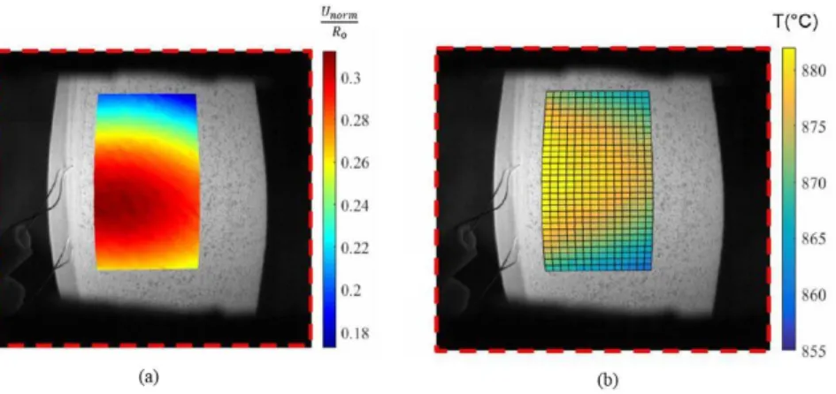
These two assumptions enabled computing the thermal field at each time step on the deformed correlation mesh. This thermal field is smooth, because non-affected by the speckle pattern. No interpolation or smoothing operation were finally necessary. An example of “coupled fields” is presented in Figure 6. The uncertainty of the thermal field mainly results from the devices that are used to identify the radiometric model [6]. The thermal uncertainty is then estimated to 0.7% of the measured temperature.
Figure 6: Example of “coupled fields”: (a) Magnitude of displacement obtained by stereo-correlation normalized by the initial outer radius of the sample R0; (b) thermal field obtained by NIRT using the deformed correlation mesh obtained by 3D-DIC.
CONCLUSION
A low-cost procedure that uses only two CMOS cameras has been presented to compute in the same time the 3D-surface displacement field by stereo-correlation and the associated thermal field by NIRT. No interpolation or smoothing operation were necessary at the end. The thermal calibration was performed after-experiment in order to enable experiments to be performed without unexpected changes of the metallurgical state of the samples. This “coupled” full fields method will enable identifying constitutive laws by a finite elements method updating algorithm (FEMU).
ACKNOWLEDGMENTS
The authors acknowledge with thanks financial support of this work from EdF. The authors want also to express their thanks to J. Réthoré for allowing access to UFreckles software.
REFERENCES
[1] D. Campello, N. Tardif, M. Marwa, et al. Identification of the steady state creep behavior of Zircaloy-4 claddings
under simulated Loss-Of-Coolant Accident conditions based on a coupled experimental/numerical approach.
International Journal of Solids and Structures, 115, p. 190-199, 2017.
[2] L. Bodelot, L. Sabatier, E. Charkaluk, et al. Experimental setup for fully coupled kinematic and thermal measurements at the microstructure scale of an AISI 316L steel. Materials Science and Engineering: A, 501(1-2), 52-60. 2009
[3] A. Chrysochoos, B. Berthel, F. Latourte, Galtier, et al, Local energy analysis of high-cycle fatigue using digital image correlation and infrared thermography. The Journal of Strain Analysis for Engineering Design, 43(6), 411-422, 2008
[4] A. Maynadier, M. Poncelet, K. Lavernhe-Taillard, et al. One-shot measurement of thermal and kinematic fields: infrared image correlation (IRIC). Experimental Mechanics, 52(3), 241-255. 2012
[5] J. Réthoré, UFreckles (Version v 2.0). Zenodo. http://doi.org/10.5281/zenodo.1433776. 2018
[6] D. Campello, N. Tardif, J. Desquines, et al. Validation of a multi-modal setup for the study of Zirconium alloys
claddings’ behavior under simulated LOCA conditions. Strain, 1339, 2018. DOI:10.1111/str.12279
[7] T. Jailin, N. Tardif, J. Desquines, et al. Mechanical behavior of as-fabricated Zircaloy-4 claddings under the simulated thermo-mechanical post-DNB conditions of a Reactivity Initiated Accident (RIA). In Top Fuel 2018.
[8] J. Réthoré, T. Elguedj, P. Simon et al. On the use of NURBS functions for displacement derivatives measurement by
digital image correlation. Experimental Mechanics, 2010, vol. 50, no 7, p. 1099-1116.
[9] Y. Rotrou, T. Sentenac., Y. Le Maoult, et al. Near infrared thermography with silicon FPA-comparison to MWIR and LWIR thermography. Quantitative InfraRed Thermography Journal, 3(1), 93-115. 2006
![Figure 1: Description of ELLIE device (a) Picture of the device [6]. (b) Scheme of the setup](https://thumb-eu.123doks.com/thumbv2/123doknet/8090566.271385/3.918.141.778.711.987/figure-description-ellie-device-picture-device-scheme-setup.webp)