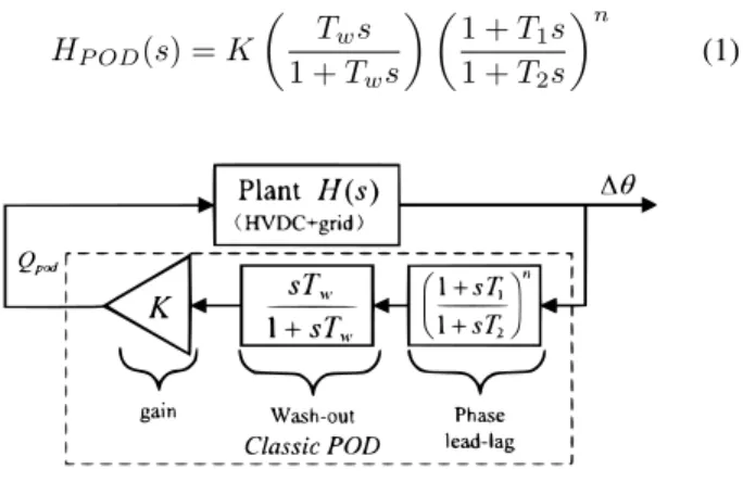
Power Oscillations Damping Controller for HVDC Inserted in Meshed AC Grids
Texte intégral
Figure


Documents relatifs
- As discussed before a + 0.6 ( f 0.4) kHz correction has been applied to the frequency of the laser locked to the Os04 saturation peaks in the large cell, to ke into
The aim of this work is to construct a reduced-order com- putational model adapted to the low-frequency range in which the synthesis of the frequency responses can be obtained
The objective of this work is to construct a reduced-order model adapted to the low-frequency range in which the synthesis of the frequency responses is obtained using only the
(2) The second one is to construct a reduced-order model with the global elastic modes but in taking into account the effects of the local elastic modes, in order to correctly
In order to construct a reduced-order model for the low-frequency band, which allows a good approximation of the global displacements to be predicted and then, if needed, to take
Since we want to construct a small-dimension reduced-order computational model which has the capability to predict the nonlinear dynamical responses on the stiff part for which
In this Section, we first summarize the method introduced in [14] which allows a reduced-order computa- tional model to be constructed for structures having a high modal density in
These two objectives are achieved using the method developed in [1]. This method is based on a kinematic reduction of the kinetic energy. Then, this reduced kinetic energy is used
