HAL Id: hal-01121856
https://hal.archives-ouvertes.fr/hal-01121856
Submitted on 4 Mar 2015
HAL is a multi-disciplinary open access
archive for the deposit and dissemination of
sci-entific research documents, whether they are
pub-lished or not. The documents may come from
teaching and research institutions in France or
abroad, or from public or private research centers.
L’archive ouverte pluridisciplinaire HAL, est
destinée au dépôt et à la diffusion de documents
scientifiques de niveau recherche, publiés ou non,
émanant des établissements d’enseignement et de
recherche français ou étrangers, des laboratoires
publics ou privés.
Dual Circularly Polarized Reflectarray withIndependent
Control of Polarizations
Simon Mener, Raphaël Gillard, Ronan Sauleau, Anthony Bellion, Patrick
Potier
To cite this version:
Simon Mener, Raphaël Gillard, Ronan Sauleau, Anthony Bellion, Patrick Potier. Dual Circularly
Polarized Reflectarray withIndependent Control of Polarizations. IEEE Transactions on Antennas
and Propagation, Institute of Electrical and Electronics Engineers, 2015, 63 (4), pp.1877 - 1881.
�10.1109/tap.2015.2398458�. �hal-01121856�
1
Dual Circularly Polarized Reflectarray with
Independent Control of Polarizations
Simon Mener, Raphael Gillard, Member, IEEE, Ronan Sauleau, Senior Member, IEEE, Anthony Bellion, Patrick Potier
Abstract— A reflectarray with independent dual-circular
polarizations is proposed for the first time. The reflector panel operates in X-band and contains 97 unit-cells. It is made with a lego-type configuration allowing changing manually the phase aperture distribution and demonstrating experimentally the independence of both polarizations in the same frequency band. To this end, various beam pointing directions are selected in right-hand and left-right-hand polarizations. The achieved bandwidth is 790 MHz (9.4% at the center frequency 8.37 GHz) for an axial ratio lower than 3.5 dB with 1.5 dB gain variations.
Index Terms— polarized passive reflectarray,
Dual-circular polarizations.
I. INTRODUCTION
EFLECTARRAYS [1] combine the benefits of reflector antennas and printed arrays for the design of high-performance antenna systems with single or multiple beam configurations. Recently, several reflectarrays operating in dual linear polarizations have been proposed using unit-cells with the desirable reflection phase over a wide frequency range, e.g. [2]-[4]. In several applications including satellite communications, circular polarization (CP) is preferred to prevent from losses due to polarization misalignment. Many CP reflectarrays have already been designed, e.g. [5]-[8], and excellent performances (large bandwidth, low cross-polarization, etc.) have been reported for single CP.
Nevertheless only a very few papers deal with dual CP reflectarrays. Moreover all of them consider a different frequency band for Left Hand (LH) and Right Hand (RH) CP [9]-[12]. To the author’s best knowledge, the problem of dual CP with independent control in the same frequency has not been addressed yet. The main objective of this paper is thus to propose a dual CP reflectarray able to control separately the two incident polarizations so as to produce two independent radiation patterns in the same frequency band.
The proposed reflectarray relies on the unit-cell studied in [14]. This cell, designed for a future reconfigurable reflectarray,
Manuscript received December, 12, 2015. This work was supported in part by the Centre National d’Etudes Spatiales (CNES) and in part by the Direction Générale de l’Armement (DGA).
S. Mener and R. Gillard are with the Institut d’Electronique et de Télécommunications de Rennes (IETR), UMR CNRS 6164, Université Européenne de Bretagne, INSA de Rennes, 35708 Rennes (e-mail : simon.mener@insa-rennes.fr).
R. Sauleau is with the Institut d’Electronique et de Télécommunications de Rennes (IETR), UMR CNRS 6164, Université de Rennes 1, 35042 Rennes (ronan.sauleau@univ-rennes1.fr).
A. Bellion is with CNES, 31401, Toulouse cedex 9, France (anthony.bellion@cnes.fr).
P. Potier is with the DGA Maîtrise de l’Information, BP 57419, 35174, Bruz cedex, France (patrick.potier@dga.defense.gouv.fr).
provides four uniformly-distributed phase states in each CP by using a convenient switching mechanism to select one reflecting element out of four possible ones. The four elements differ in their rotation angle, which is a classical means of varying the reflected phase for CP reflectarrays [15]. In the present paper, only frozen states are considered; this means that switches are replaced by short circuits in the on-state and by open circuits in the off-state.
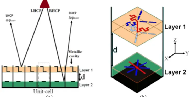
More precisely, this unit-cell consists of two layers as represented in Fig. 1. The first layer is a Left Hand Circular Polarization Selective Surface (LH-CPSS) that controls the reflection phase of the incident LHCP while transmitting the RHCP to the second layer [16]. The reflecting elements forming this CPSS are crank-shaped 3/4 dipoles printed on both faces of a dielectric stack-up (see Ref. [16] for technological details). Four such elements with different rotation angles are combined in each unit-cell to provide four different phase states. The connected element (shown in red in Fig. 1b, layer 1) thus defines the reflected phase in LHCP. In [16], this first layer has been characterized experimentally in X-band using a waveguide simulator (the unit-cell is embedded inside a square metallic waveguide with 22.88×22.88mm2 cross-section). The achieved isolation between both CP was better than 15 dB at 8.5 GHz.
(a) (b)
Fig. 1. (a) Principle of the proposed reflectarray with independent control of both incident CP. (b) Unit-cell with dual CP control.
Next, the second layer uses a quite standard CP unit-cell that reflects the incident RHCP with the appropriate phase shift. The reflected RHCP then propagates back through the first layer again without being disturbed by the CPSS. Here, the chosen CP unit-cell is a combination of four rotated /2 dipoles printed on a single substrate backed by a ground plane, as derived from [15].
Finally, in the complete unit-cell, both layers are combined and separated by an air gap (thickness d in Fig. 1). The main characteristics of this unit-cell have been studied experimentally in [14]. A phase resolution better than 1.92 bits [17] with insertion loss lower than 1 dB has been obtained in LHCP and RHCP over a 355 MHz frequency range around 8.37 GHz.
Here we demonstrate the capabilities of this promising cell in a real array configuration. To this end, a reflectarray demonstrator is fabricated and measured in X-band. Different scanning configurations are considered for both CP to demonstrate the independent control that can be achieved. A Lego-like construction of the radiating panel has been implemented to easily synthesize and measure various radiation
2
configurations. For this validation step, emphasis is thus clearly put on the diversity of the tested configurations rather than on the optimization of one particular configuration.
The paper is organized as follows. The design and fabrication of the proposed reflectarray are described in Section II. The performance in dual CP is reported in Section III for several radiation configurations. Finally, conclusions are drawn in Section IV.
II. ANTENNA TOPOLOGY AND TECHNOLOGY
As explained in Section I, the proposed unit-cell is made of two independent printed layers, each one controlling one of the two CP with a phase resolution close to 2-bit. In the fabricated reflectarray, both layers are separated by a distance d and are stacked in a metallic cavity (same cross-section as the waveguide simulator used in [14] and [16]). This metallic cavity presents several advantages: i) it provides the necessary frame to mechanically support the two layers while ensuring the convenient spacing in-between, ii) it prevents from mutual coupling (due to surface waves) between adjacent cells and guarantees that the operating mode is close to the one considered when studying the single unit-cell (i.e. in a metallic waveguide), iii) it improves the robustness of the CPSS layer with regards to incidence angle [18].
In practice, the metallic frame supporting the cells is made of five blocks (Fig. 2a). At the top, a 30-mm thick metallic grid is used as an extension of the metallic cavities above the CPSS substrate. Just underneath, layer 1 is the upper part of the metallic cavities hosting the LH-CPSS unit-cells; its height (8.49mm) corresponds to the thickness of the CPSS substrate. Then, empty metallic cavities (with a thickness d=20 mm) provide the air spacer between the LH-CPSS and RHCP cells. Layer 2 is the bottom part of the metallic cavities hosting the RHCP unit-cells; its height (6.75mm) corresponds to the thickness of the RHCP substrate. Finally, the cavities are backed by a ground plane.
(a) (b)
Fig. 2. (a) Fabricated reflector panel composed of 5 layers. (b) Reflectarray with matching dielectric layer.
Such a topology permits a Lego-like construction of the reflectarray panel. For instance, any phase law for the LHCP can be synthetized by filling up the cavities of layer 1 with the appropriate elementary cells. Only layer 1 (respectively layer 2) has to be updated when a new radio-coverage in LHCP (respectively RHCP) is desired.
The reflectarray panel has been designed at 8.37 GHz and is composed of 97 unit-cells in a circular-like arrangement (Fig. 2). The f/D ratio equals 0.8 and the primary source is placed at the center of the reflector panel (f=210mm). The inter-element spacing dcell is 23.88mm (0.66λ0 at 8.37 GHz). The primary
source is a circular horn that can operate either in LHCP or in RHCP. Its gain equals 10 dBi (40° HPBW) and cross polarization level is only 12 dB under the co-polarization maximum. The edge taper is -6 dB, and the maximum incidence angle is 30°. The grid is covered by a dielectric matching layer (as seen in white in Fig. 2b) whose thickness and dielectric constant are 12 mm and 1.65 respectively. It has been optimized in simulation (not shown) to guarantee that 99% of the incident power enters into the cavities over the entire frequency band (8.2-8.8 GHz).
III. STUDIED CONFIGURATIONS AND EXPERIMENTAL RESULTS
A. Studied configurations
Table I summarizes the five configurations studied here. Configurations 1 to 3 correspond to three different pointing angles for the LHCP beam while the RHCP pattern points at broadside. Only Layer 1 differs from one configuration to the other one. For configurations 1, 4 and 5, the LHCP main beam points at broadside, whereas it varies in RHCP.
TABLEI
CHARACTERISTICS OF THE FIVE STUDIED CONFIGURATIONS
Configuration Main beam direction for LHCP
Main beam direction for RHCP 1 θ=0° θ=0° 2 θ=+12°, φ=90° θ=0° 3 θ=+21°, φ=90° θ=0° 4 θ=0° θ=5°, φ=180° 5 θ=0° θ=22°, φ=180°
As an example, Fig. 3 represents the layout in LHCP (Fig. 3a) and RHCP (Fig. 3b) for configuration 1 (radiation at broadside for both polarizations).
(a) (b) Fig. 3. Layouts for configuration 1. (a) LHCP layer. (b) RHCP layer.
B. Radiation at broadside for LHCP and RHCP
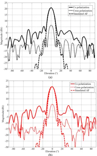
Fig. 4 represents the radiation patterns measured at the center frequency (8.37 GHz) in φ=0° plane for configuration 1. It demonstrates promising performance with well-defined beams at broadside for both polarizations. The measured side lobe and cross polarization levels are lower than 15 dB below the maximum co-polarization level. Note that the quite poor polarization quality of the feed horn certainly alters that of the reflectarray.
(a)
(b)
Fig. 4. Configuration 1. Measured radiation patterns (φ=0° plane) at 8.37 GHz. (a) LHCP. (b) RHCP. Simulation of array factor (AF) is added for comparison.
The ratio of the reflectarray gain over the directivity of a uniform aperture of identical size is only 25%. It can be explained as follows: 1.5 dB spillover loss, at least 0.9 dB phase quantization loss, 0.5 dB insertion loss in the unit-cell [14], 0.2dB cross-polarization loss and 0.2 dB loss due to taper efficiency. The remaining 2.9 dB loss is mainly attributed to feed blockage (as the horn is quite large compared to the array), but other effects could also contribute (horn CP degradation out of broadside, lower cell efficiency at higher incidence, imperfect estimation of horn phase center, etc.). The frequency dependence of the antenna gain and axial ratio (AR) are plotted in Fig. 5 (note that, in all the paper, red color is used for RHCP and black for LHCP). This figure shows that the axial ratio is better than 3.5dB over a 790 MHz bandwidth spanning from 8.04 to 8.83GHz. In this range, the gain variations remain smaller than 1.5dB. The smaller gain in RHCP is due to additional loss when the RHCP wave propagates through the LH-CPSS.
C. Scanned beams
Fig. 6 represents the radiation patterns for configurations 2 and 3 in the φ=90° plane. As can be observed, the LHCP beam is scanned up to 21° (Fig. 6a) without significantly affecting the RHCP beam at broadside (Fig. 6b). This demonstrates the independence of both circular polarizations. Furthermore,
whatever the configuration, the measured side lobes and cross polarization levels are better than 14 dB.
Fig. 5. Measured axial ratio and gain at broadside (configuration 1).
(a)
(b)
Fig. 6. Configurations 2 and 3. Measured radiation patterns (φ=90° plane) at 8.37 GHz. (a) LHCP. (b) RHCP.
Quite similar performance are obtained for configurations 4 and 5 (when the RHCP beam is scanned) as shown in Fig. 7. Table II compares the simulated and measured radiation characteristics. The agreement is quite good, especially for main beam direction (discrepancy lower than 0.4°).
4
(a)
(b)
Fig. 7. Configurations 4 and 5. Measured radiation patterns (φ=180° plane) at 8.37 GHz. (a) LHCP. (b) RHCP.
The observed differences in the beamwidth (up to 2.4°) can be caused by the approximations used in the computation: array theory is used and the pattern of the unit-cell is approached by that of a square waveguide in an infinite periodic array. For all configurations, axial ratio in the main beam (not shown) is less than 3 dB for both RHCP and LHCP.
TABLEII
SIMULATED AND MEASURED BEAM CHARACTERISTICS AT 8.37GHZ
Configuration Simulated main beam direction Measured main beam direction Simulated beamwidth Measured beamwidth 1 (LH/RHCP) 0°/0° -0.1°/-0.3° 8.2°/8.2° 9.2°/8.7° 2 (LHCP) 12° 12.2° 8.8° 9.8° 3 (LHCP) 21° 21.4° 9.2° 10.2° 4 (RHCP) 5° 5.2° 8.4° 10.8° 5 (RHCP) 22° 22.4° 9.4° 11.7° IV. CONCLUSION
This paper describes for the first time a reflectarray able to produce two different radio-coverages in dual CP at the same frequency. The antenna panel is made of 97 unit-cells combining two reflecting layers. Various configurations have been studied experimentally, with different main beam directions in RHCP and LHCP. The selected configurations demonstrate unambiguously a very good isolation between both
polarizations. The measured side lobe and cross-polarization levels are better than 14 dB over a 790 MHz-bandwidth around the center frequency (8.37 GHz).
REFERENCES
[1] J. Huang and J. A. Encinar, “Reflectarray antennas,” Wiley-IEEE Press, ISBN: 978-0-470-08491-5, Nov. 2007.
[2] J. A. Encinar, L. Sh. Datashvili, J. Zornoza, M. Arrebola, M. Sierra-Castañer, J. Besada-Sanmartín, H. Baier, and H. Legay, “Dual-polarization dual-coverage reflectarray for space applications,” IEEE Trans. Antennas Propag, vol. 54, no. 10. pp. 2827-2836, Oct. 2006. [3] T. Toyoda, D. Higashi, H. Deguchi, and M. Tsuji, “Broadband
reflectarray with convex strip elements for dual-polarization use,” Proceeding of the International Symposium on Electromagnetic Theory (EMTS 2013), 20-24 May 2013, Hiroshima, Japan.
[4] R. E. Hodges and M. Zawadzki, “Design of a large dual polarized Ku band reflectarray for space borne radar altimeter,” IEEE Antennas Propag. Soc. Int. Symp., vol. 4, Monterey (CA), pp. 4356-4359, 2004. [5] A. E. Martynyuk and J. I. Martinez Lopez, “Reflective antenna arrays
based on shorted ring slots,” IEEE Microwave Symp. Dig., vol. 2, pp. 1379-1382, Phoenix (AZ), May 2001.
[6] A. Yu, F. Yang, A. Z. Elsherbeni, and J. Huang, “An X-band circularly polarized reflectarray using split square ring elements and the modified element rotation technique,” IEEE Antennas Propag. Soc. Int. Symp., San Diego (CA), Jul. 2008.
[7] S. Malfajani and Z. Atlasbaf, “Design and implementation of a broadband single layer circularly polarized reflectarray antenna,” IEEE Antennas Wireless Propag. Lett., vol. 11, pp. 973-976, 2012.
[8] B. Strassner, C. Han, and K. Chang, “Circularly polarized reflectarray with microstrip ring elements having variable rotation angles,” IEEE Trans. Antennas Propag., vol. 52, no. 4, pp. 1122-1125, Apr. 2004. [9] C. Han, C. Rodenbeck, J. Huang, and K. Chang, “A C/Ka dual frequency
dual layer circularly polarized reflectarray antenna with microstrip ring elements,” IEEE Trans. Antennas Propag., vol. 52, no. 11, pp. 2871-2876, Nov. 2004.
[10] J. Huang, C. Han, and K. Chang, “A Cassegrain offset-fed dual-band reflectarray,” IEEE Antennas Propag. Soc. Int. Symp., Albuquerque (NM), pp. 2439-2442, Jul. 2006.
[11] A. Yu, F. Yang, A. Z. Elsherbeni, and J. Huang, “Experimental demonstration of a single layer tri-band circularly polarized reflectarray,” IEEE Antennas Propag. Soc. Int. Symp., Toronto, Canada, 11-17 Jul. 2010.
[12] C. Guclu, J. Perruisseau-Carrier, and O. A. Civi, “Proof of concept of a dual-band circularly-polarized RF MEMS beam-switching reflectarray,” IEEE Trans. Antennas Propag., vol. 60, no. 11, pp. 5451-5455, Nov. 2012.
[13] J. Huang and R. J. Pogorzelski, “A Ka-band microstrip reflectarray with elements having variable rotation angles,” IEEE Trans. Antennas Propag, vol. 46, no. 5, pp. 650-656, May 1998.
[14] S. Mener, R. Gillard, R. Sauleau, A. Bellion, and P. Potier, “Unit-cell for dual-circular polarisation reflectarrays,” Proceedings of the 8th European
Conference Antennas and Propag., The Hague, Netherlands, 6-11 Apr. 2014. Accepted paper.
[15] E. Girard, R. Moulinet, R. Gillard, and H. Legay, “An FDTD optimization of a circularly polarized reflectarray unit cell,” IEEE Antennas Propag. Soc. Int. Symp., San Antonio (TX), vol. 3, pp. 136-139, Jun. 2002.
[16] S. Mener, R. Gillard, R. Sauleau, C. Cheymol, and P. Potier, “Design and characterization of a CPSS-based unit-cell for circularly-polarized reflectarray applications,” IEEE Trans. Antennas Propag, vol. 61, no. 4, pp. 2313-2318, Apr. 2013.
[17] R. Pereira, R. Gillard, R. Sauleau, T. Dousset, X. Delestre, ”Dual linearly-polarized unit-cells with nearly 2-bit resolution for reflectarray applications in X-band”, IEEE Trans. Antennas Propag., vol. 60, no. 12, pp. 6042-6048, Dec. 2012.
[18] S. Mener, R. Gillard, R. Sauleau, C. Cheymol, and P. Potier, “An improved topology for reconfigurable CPSS-based reflectarray cell,” EuCAP, 8-12 Apr. 2013, Gothenburg, Sweden.