HAL Id: hal-00620858
https://hal.archives-ouvertes.fr/hal-00620858
Submitted on 9 Sep 2011
HAL is a multi-disciplinary open access archive for the deposit and dissemination of sci-entific research documents, whether they are pub-lished or not. The documents may come from teaching and research institutions in France or abroad, or from public or private research centers.
L’archive ouverte pluridisciplinaire HAL, est destinée au dépôt et à la diffusion de documents scientifiques de niveau recherche, publiés ou non, émanant des établissements d’enseignement et de recherche français ou étrangers, des laboratoires publics ou privés.
Understanding the dual mobility concept for total hip
arthroplasty. Investigations on a multiscale
analysis-highlighting the role of arthrofibrosis
Jean Geringer, Bertrand Boyer, Frédéric Farizon
To cite this version:
Jean Geringer, Bertrand Boyer, Frédéric Farizon. Understanding the dual mobility concept for total hip arthroplasty. Investigations on a multiscale analysis-highlighting the role of arthrofibrosis. Wear, Elsevier, 2011, 271 (9-10), pp.2379-2385. �10.1016/j.wear.2011.02.027�. �hal-00620858�
Ref N°: 0313, Geringer, Understanding the Dual mobility concept for total hip arthroplasty. Investigations on a multiscale analysis
1
Understanding the Dual mobility concept for total hip
arthroplasty. Investigations on a multiscale analysis-Highlighting
the role of arthrofibrosis
J. Geringer
a,*, B. Boyer
a,b, F. Farizon
ba Ecole Nationale Supérieure des Mines de Saint-Etienne, ENSM-SE,Center for Health Engineering, UMR CNRS 5146, IFR 143
Department of Biomechanics and Biomaterials-Biotribocorrosion,, 158 cours Fauriel, F-42023 Saint-Etienne Cedex 02 Tel: +(33).4.77.42.66.88; geringer@emse.fr
b Centre d’Orthopédie Traumatologie CHU St Etienne F-42055 St Etienne cedex 2
Received Date Line (to be inserted by Production) (8 pt)
Abstract
In hip implants, UHMWPE (Ultra High Molecular Weight Polyethylene) liner wear is believed to be a key issue affecting the lifetime of the artificial joint. Dual mobility, a THA (Total Hip Arthroplasty) concept where the liner moves inside the metallic shell, has become popular due to its low dislocation rate. To understand the tribological behavior of this particular implant, especially the role of the second mobility, 12 representative explants were selected from a bank of 250 explants. The implants used were Profil® femoral stem and Novae® metallic shell. The external surface, involved in the second mobility, was examined by 3D profilometry, SEM (Scanning Electron Microscopy) and CMM (Coordinate Measuring Machine). This study highlights a correlation between roughness and CMM evolutions and surgical parameters. A particular wear zone and a wear scenario were identified and validated according to the type of metal-back. A metal transfer between the metal back and the liner was isolated. CMM allowed to measure second mobility wear volume at a macroscopic scale. Thus a realistic wear mechanism has been suggested for this specific implant.
Keywords: Hip replacement prosthesis, Dual mobility concept, Ultra High Molecular Weight Polyethylene,
Wear mechanism, Surface roughness.
1. Introduction
Sir John Charnley introduced, for the first time, the use of polyethylene liner against a metallic femoral head, SS 316L [1]. This couple of materials became the Gold standard, i.e. the reference for the hip arthroplasty. This smooth (liner)-hard (head) couple was an alternative to others, as metal on metal, Mc Kee and Watson-Farrar [2] or ceramic on ceramic, Boutin [3].This couple of materials became the Gold standard. The head diameter chosen was 22.2 mm, more than half the normal femoral head diameter, to decrease wear rates. In 1975, to overcome the early impingement issue, causing a mean dislocation rate of 5 %, the dual mobility socket was introduced by Pr. Gilles Bousquet [4-6]. This concept was based on two articulating surfaces instead of one – between femoral head and UHMWPE liner, as well as between UHMWPE liner and metal back, Figure 1. The second mobility exists because of a retentive chamfer maintaining head and liner together, thus allowing increasing head diameter while following Charnley 22.2 mm low friction philosophy.
*Corresponding author. Tel.: +33 477 426 688; fax: +33 477 420 157. E-mail address: geringer@emse.fr; jgeringer@voila.fr (Jean Geringer)
Ref N°: 0313, Geringer, Understanding the Dual mobility concept for total hip arthroplasty. Investigations on a multiscale analysis
2
The usual liner-head assembly is constituted on ly by the first mobility. This new implant enhanced both stability and survivorship because of decreasing dislocations [7-10]. The follow-up studies of dual mobility concept exhibited similar behaviors to classical THA in prosthetic joint lifetime [11-15]. To prevent dislocation due to impingement, the dual mobility concept seems to be the most reliable treatment [16]. The second mobility is believed to be triggered when the femoral neck hits the liner. It lowers liner rim degradations and generation of wear debris. Dual mobility concept is concerned in 30% of THA in France, and is more and more investigated for the implants in US. Considering an extra friction surface, one might expect dual mobility to produce more wear debris than the classical artificial joint; the osteolysis mechanisms might be reinforced. The main key-points related to dual mobility are the understanding of the in-vivo biomechanical behavior, the wear rate of UHMWPE involved in the second mobility and the material transfers due to wear and corrosion between the cup and the metal back.Figure 1 Dual mobility hip implant; *: first mobility between head and cup, concave side for cup; **: second mobility between cup and metal back, convexe side for cup
In this study, the explant convex side was investigated for understanding the evolution of surface morphologies. The main aim was to analyze friction zones, wear orientation and total wear rates (from concave and convex sides). Finally, from these experiment results, including a specific treatment of data such as selecting the relevant roughness parameters, a tribological scenario might be determined for highlighting the main wear steps and understanding the in vivo course of the second mobility.
2- Materials and methods
2.1. Explanted prostheses, implant selection
Since 1990, all explanted prostheses are stocked for scientific and legal purposes. The cleaning protocol consists in a curing with an antiseptic product, without sterilization process to avoid changes of the mechanical properties due to water absorption. Among the thousands of explants, over 250 dual mobility explants were available. A drastic selection of explants was practiced, based on clinical criteria, to get only the prosthetic elements without other complication than pure liner wear.
Different factors have to be considered for avoiding the mismatching of the selected explants. The
Metal back
Dual mobility liner
Ischum
Acetabulum
prosthesis
Femoral bone
**
*
Ref N°: 0313, Geringer, Understanding the Dual mobility concept for total hip arthroplasty. Investigations on a multiscale analysis
3
following factors were taken into account for excluding implants:- loosening and osteolysis because cup wear could be increased compared to an actual behavior without extra wear debris [17-20]. Moreover loosening itself could cause extra mobility and it could confuse the wear scenarii.
- septic revision because of suspicion of a non usual triggering of the dual mobility socket. - explants from peri-prosthetic fractures because of mismatching of the hip joint and mobility
triggering.
- explants from second revision (or more) revision to avoid combinations of different materials.
Finally, the same implant was selected (implant stem ‘Profil’ from the SERF company manufactured between 1988 and 1998), with the same neck length, the same head diameter (22.2 mm) and head material (Co-Cr alloy). The neck length is significant in the positioning. The metal back could be manufactured in titanium alloy Ti-6Al-4V or stainless steel 316L. As both materials could involve a particular mobility of the cup, it has been decided to consider two liner-metal back couples: UHMWPE/Ti-6Al-4V and UHMWPE/316L. The contact between the liner and metal-back is submitted to the weak forces, specific to the materials in contact. The socket mobility will be triggered according to the material in contact.
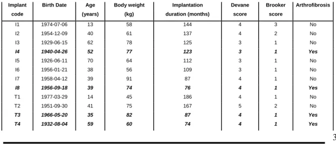
After taking into account these clinical factors, 12 explants were selected from the initial group of 250, each representing a distinct population of patients or implants. From the 12, 8 were stainless steel metal-backed explants, 4 were titanium alloy metal-backed explants. We decided to include a genuine UHMWPE cup, manufactured in 1993 for integrating the influence of the initial surface on the wear behavior. All clinical and material parameters were described on Table 1 and Table 2. The Devane score is related to the patient activity label, Table 3 [21]. It is useful for quantifying the sedentary activity from the high level physical activity (competitive sport for example). The Brooker score is useful for quantifying the peri-prosthetic ossifications, Table 4 [22,23]. It is related to the hip joint mobility according to the space between opposing bone surfaces from ossification with huge distance to ossification with ankylosis of hip joint, i.e. bone coalesce. This score will point out information about the mobility of the artificial hip joint during the in vivo joint running. Peri-prosthetic arthrofibrosis is an element that has to be mentioned in operative reports. It states that the articular capsule is thickened, limiting hip movements.
Table 1: clinical data from patients.
Implant Birth Date Age Body weight Implantation Devane Brooker Arthrofibrosis code (years) (kg) duration (months) score score
I1 1974-07-06 13 58 144 4 3 No I2 1954-12-09 40 61 137 4 2 No I3 1929-06-15 62 78 125 3 1 No I4 1940-04-26 52 77 123 3 1 Yes I5 1926-06-11 70 64 112 3 1 No I6 1956-01-21 38 56 109 3 1 No I7 1958-04-12 39 91 87 4 1 No I8 1956-09-18 39 74 76 4 1 Yes T1 1977-03-29 14 45 186 4 1 No T2 1951-09-30 41 75 167 5 2 No T3 1966-05-20 35 82 87 4 1 Yes T4 1932-08-04 59 60 74 4 1 Yes
Ref N°: 0313, Geringer, Understanding the Dual mobility concept for total hip arthroplasty. Investigations on a multiscale analysis
4
Table 2: implant data from the operative report, metal back material, metal back diameter, inclination and post-operative data, strip wear approximately upper to the equator on the convex side of the cup, .
Table 3: Devane score and the related activity [21].
Table 4: Brooker score and related peri-prosthetic ossification [22,23].
2.2. Roughness investigations
While the explants were selected, macroscopic analysis allowed highlighting a strip wear close to the liner convex side equator. The evolution of the roughness parameters was fruitful for isolating the particular wear zones and for pointing out the significant wear zones. The specific methodology dedicated to this study was established from [24-28]. Thus, in order to characterize quantitatively the wear mechanism at a microscale, the following analyses were practised: analyses of 11 zones on the convex side of each UHMWPE liner, i.e. 5 areas on the no-worn zone (latitude 2 as depicted on Figure 2), 5 areas on the worn zone (latitude 3, Figure 2) and 1 zone on the liner apex.
The profilometry analyses were investigated using a mechanical profilometer SOMICRONIC®. The measurement interval in X and Y was 4 µm. The images resolution was 256 x 256 points. The raw data were filtered using a least squares plane and a B-spline filter; the cut-off length was of 2 mm. As the surface is spherical, a particular attention was paid on the influence of the area size on the roughness parameters. Moreover, reproductibility was investigated on a single cup. Finally, the maximum area of measurements was chosen equal to 1 mm2. 11 zones of 1 mm2 for one liner were considered; these analyses were practised on 12 explanted liners and on a reference liner (total of 141 areas). The Figure 3 presents a typical 3D area after
Implant Metal back Metal-back Inclination Strip wear code Material diameter (mm) (°)
I1 SS 316L 51 45 No I2 SS 316L 57 50 Yes I3 SS 316L 51 45 Yes I4 SS 316L 45 45 No I5 SS 316L 59 45 Yes I6 SS 316L 53 45 Yes I7 SS 316L 47 45 Yes I8 SS 316L 51 45 No T1 Ti-6Al-4V 43 45 Yes T2 Ti-6Al-4V 55 45 No T3 Ti-6Al-4V 57 45 No T4 Ti-6Al-4V 57 45 No
Brooker score Activity
4 Islands of bone within soft tissues about the hip
3 Bone spurs from the pelvis or proximal end of the femur, leaving at least 1 cm between opposing bone surfaces 2 Bone spurs from the pelvis or proximal to end of the femur, reducing the space between opposing bone surfaces <1 cm 1 Apparent hip ankylosis
Devane score Patient activity level
5 Employed in strenuous manual labor, contact sport, competitive tennis 4 Employed in light job (desk), noncontact sport (golf) or social tennis 3 Leisure activity, gardening, light level of swimming
2 Semi-sedentary activity, home activity 1 Sedentary activity, dependant on assistance
Ref N°: 0313, Geringer, Understanding the Dual mobility concept for total hip arthroplasty. Investigations on a multiscale analysis
5
filtering, it is related to the T1 UHMWPE convex area of the worn zone, latitude of 60-80° close to the equator (latitude of the zone 3-Figure 2b), Figure 3a. The Figure 3b is related to the apex zone, summit of the convex area (zone 2-Figure 2b). The software Matlab® allowed drawing surface area from the filtered data. From the comparison of the images, one may notice that the peak heights of the worn zone are higher than the ones of the apex zone. Further results would exhibit the roughness parameters extracted from these topographical data.Figure 2 a) Cestilène® (UHMWPE) liner with functional dimensioning and tolerancing; b) zone 1: apex ; zone 2: no-worn zone; zone 3: worn zone
Figure 3 a) example of a worn zone close to equator, b) example of apex zone close to the latitude of 40°, the related explant is T1.
The aim of this study was to revealed the most relevant roughness parameters for distinguishing the no-worn and no-worn zones from the convex side of the UHMWPE liner. From the filtered data, various roughness parameters were evaluated:
- the amplitude parameters: Sa, Sz, Sq, Ssk, Sku ;
- the spatial parameters Sds:, Str ; both parameters were extracted from the 3D roughness analysis; - the Abbott-Firestone parameters: Srpk, Srpkm, Srvk, Srvkm, Srk, Smr1, Smr2, Sv1 et Sv2.
All parameters were defined in [26] and in ISO standard 25178. As example, the Figure 3a shows the evolution of Sa according to the liner type and the Figure 3b.
It is worth noting that a part of the roughness parameters was relevant for distinguishing worn and no-worn zones and the different explants, Sa parameter. Otherwise, Sds, the summits density, did not allow distinguishing different explants. The complete analysis would be investigated in the results part.
a)
1 2
3
b)Ref N°: 0313, Geringer, Understanding the Dual mobility concept for total hip arthroplasty. Investigations on a multiscale analysis
6
2.3. Tridimensional measurements, 3D CMM
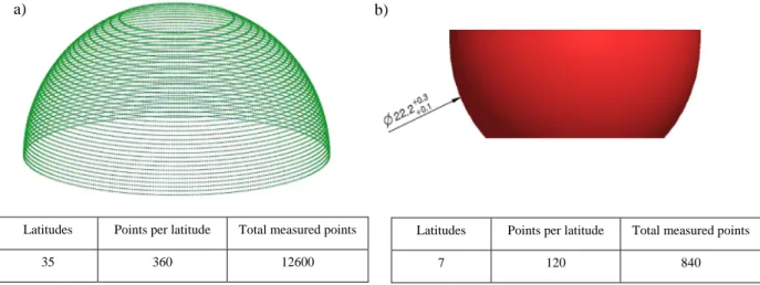
A 3 Dimensional Co-ordinate Measure Machine (3D CMM), Mahr® MMQ, was used on dual mobility liner convex sides. The main goal of these measurements was to estimate the macroscopic wear of all the UHMWPE explanted liners (convex side), thus this method allowed performing the wear volumes of the convexity. One point per degree, for each latitude, was measured. Distance between latitudes was set at 0.5 mm. More than 10,000 points per explanted liner were acquired thanks to this methodology; it aimed at decreasing the discrepancy on the wear volume. A drawback of this mechanical device was its wider probe (1 mm diameter), involving measured zone crushing. This experiment had to occur later than 3D roughness measurements because of the polishing effect after 3D CMM measurements. Using 3D CMM, liner outer surface was extrapolated and compared to the liner original blueprint, manufacturing tolerances included. Figure 4a presents three-dimensional data from 3D CMM for one explant, convex side.
Moreover, the measurements of the inside volume were carried out on all explanted liners and on the pristine liner. The number of the measured points on the concave side, Figure 4b, is lower than the one on the convex side, due to the space bulk between the 3D CMM stylus and the inner volume of the liner, 22.2 mm. The stylus positioning on the concave side is more difficult than the one on the convex side. Thus the total volume, outside and inner wear volumes, was measured on each explanted liner.
Figure 4 dimensional data, from 3D CMM, of a UHMWPE explanted liner, a) outer surface (second mobility, convex side), 35 latitudes, 360 points per latitude, 12600 measured points; b) inner surface (first mobility, concave side), 7 latitudes, 120
points per latitude, 840 measured points.
2.4 Scanning Electron Microscopy Observations
Convex sides of three UHMWPE liners were analyzed. This last test tends to be destructive because of the metallization layer, gold deposit. A scanning electron microscope, MEB JEOL 6400, was chosen, including Electron Dispersive Spectroscopy probing in order to analyse metallic shell particle transfers to the surface of the liner. Sharp settings of the gold metallization protocol allowed to get images with a maximum magnification of 30000. Apex, worn zone and no-worn zone images were obtained.
Latitudes Points per latitude Total measured points 35 360 12600
Latitudes Points per latitude Total measured points
7 120 840
b) a)
Ref N°: 0313, Geringer, Understanding the Dual mobility concept for total hip arthroplasty. Investigations on a multiscale analysis
7
3. Results and discussion3.1. Worn volumes by CMM
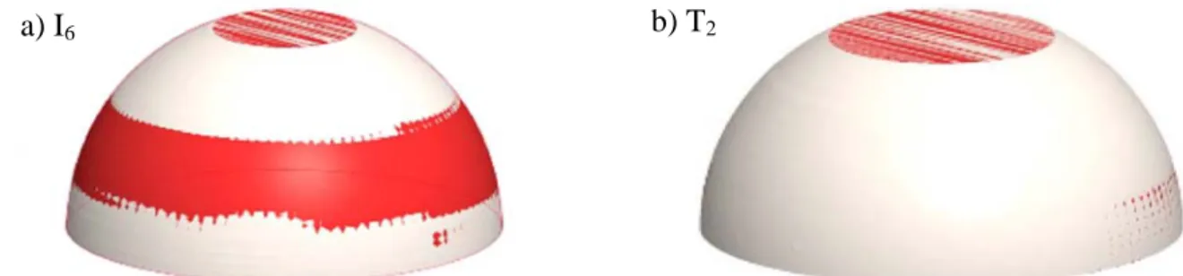
The twelve explants were analyzed using 3D CMM. The pristine liner was used as reference, calibrating the measurement of wear volume. Figure 5 represents the liner volume, in white, according to the manufacturing minimal diameter. The red stripe corresponds to a zone where the measured diameter was inferior than this minimal manufacturing diameter. Apex was not measured on this experiment. As no wear stripe was found in this zone, we estimated unnecessary to add apex dimensional data. This wear stripe was viewed on all arthrofibrosis-free explants, it is typical to a specific worn zone of a dual mobility liner.
Table 5 presents 3 D convex (second mobility), concave (first mobility) and total wear volumes of dual mobility liners. The average wear volume corresponds to the mean of the minimal and maximal wear volumes that were calculated from the biggest (smallest) radius according to manufacturing data, and the 3D CMM measured volume, actual volume after explantation. Wear in mm3/year corresponds to the ratio between total wear volume and implant survival, i.e. implant duration. Negative values, for the concave side, probably signify that manufacturing blueprint guidelines were not precisely respected.
Figure 5 Three dimensional CMM a) Explant I6 ; b) Explant T2 ; the red stripe represents the zone where measured diameter was below the minimal manufacturing diameter.
Starting from acquired data, it had been impossible to find a significant tendency between wear volume and metal back composition, peri-prosthetic arthrofibrosis presence or patient parameters.
3.2. Roughness measurements analysis
The analysis, on Table 6, of all available 3D roughness parameters and the Abbott-Firestone parameters allows classifying the relevant ones. An ANOVA test (p < 0.05) was investigated for highlighting whether the roughness parameters were relevant or not for discriminating the no-worn zone from the worn zone on the convex side, for each implant.
The Table 6 exhibits the relevant 3D roughness parameters for differentiating the wear zone from the no-worn zone. As mentioned in Figure 6, wear was approximately located upper to the equator on the convex side of the liner. It is worth noting that Ssk parameter was highlighted.
Table 5 3D CMM annual wear volumes, depending on metal back material, presence of peri-prosthetic arthrofibrosis and implant duration; Range is the difference between the maximum and minimum values of wear volume; SD is the standard deviation; MB: Metal-back; SS: Stainless Steel; Brooker: Brooker score.
Ref N°: 0313, Geringer, Understanding the Dual mobility concept for total hip arthroplasty. Investigations on a multiscale analysis
8
Table 6 Classification of the roughness parameters in order to highlight the relevant parameter according to ANOVA test (p < 0.05)
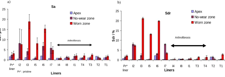
The Figure 7 shows the evolution of Sa and Sdr parameters according to the liner type. These parameters allowed highlighting the influence of arthrofibrosis.
Figure 6 Convex side, wear volumes of dual mobility liners.
Implant survival (years)
Convex side Second mobility Average 3D annual wear, V1
(mm3/y) Convex side Second mobility Range/2 (mm3/y) Concave side First mobility Average 3D annual wear, V2 (mm3/y) Concave side FIrst mobility Range/2 (mm3/y)
Total wear volume Average 3D annual wear, V1 + V2 (mm3/y) MB SS 316L I2 11.42 0.1 8.3 22.4 2.9 22.5 I3 10.42 74.8 7.1 41.9 1.9 116.7 I5 9.33 44.1 17.5 132.2 3.6 176.3 I6 9.08 75.2 8.8 75.2 I7 7.25 1.2 16.2 -0.4 2.1 0.8 MS SS 316L Arthrofibrosis (AF) High Brooker + AF I4 10.25 24.3 4.7 0.2 1.1 24.4 I8 6.33 10.1 4.4 10.1 I1 12 32.9 6.0 15.2 1.7 48.1 MB Ti-6Al-4V (AF) T4 6.17 76.2 15.1 -7.9 3.2 68.3 T3 7.25 46.9 25.7 0.5 2.7 47.4 MB Ti-6Al-4V T2 13.92 15.0 5.9 25.2 1.4 40.2 T1 15.5 13.2 2.8 4.0 1.3 17.2
Mean Mean Mean Mean
9.91 36.7 ± 29.1 (SD) 22.1 ± 39.2 53.9 ± 50.3
No relevance Relevant The most relevant Wear process
Sku, Sds, Str Sa, St, Sq Sdr Ssk Srpk, Srpkm, SRvk, SRvkm, SMR1, SMR2, SV1, SV2 SRk CMM 0 20 40 60 80 100 120 140 160 180 I2 I3 I5 I6 I7 I4 I8 I1 T4 T3 T2 T1 Liners W ear vo lu me mm 3 /y ea r
Total wear volume 2nd mobility wear volume
Arthrofibrosis
* **
* : I8, lack of convex side measurement ** : I6, lack of concave side measurement
Ref N°: 0313, Geringer, Understanding the Dual mobility concept for total hip arthroplasty. Investigations on a multiscale analysis
9
Figure 7 a) Sa values according to liner type; b) Sdr values according to liner type.
3.3. SEM observations of convex sides
2 explants and the bulk liner were analyzed using SEM, on apex, worn zone and no-worn zone. It is worth noting that the worn zone on the stainless steel metal backed liner, i.e. the red stripe identified in the previous section on CMM, presented evidence of a damaging process that could correspond to a material pulling-out or even to a ploughing mechanism. Wear mechanisms of liner, between stainless steel and titanium alloy metallic shells, seemed rather different. One could presume that UHMWPE liner is worn by abrasion and ploughing for stainless steel metal back liners when it is more an adhesion, cracking then flaking mechanism for Ti-6Al-4V metal back. Particles found on the stainless steel MB worn zone image were the size of a millimetre. Finally, no-wear zones, whatever the metal back material, showed a polished zone, in comparison with the bulk liner image.
These observations confirmed the Sa values and even more the differences between worn and no-wear zones. Highest Sa values were found on stainless steel metal backed liners, i.e. the most damaged profiles, according to the stainless steel MB worn zone image. Also, it clearly appeared that this wear stripe was also found on titanium alloy metal backed liners.
3.4. Discussion
The CMM measurements exhibited the influence of arthrofibrosis on the triggering of the second mobility, the usual mobility, between head and liner, being preserved from wear. Average wear values could be compared to Charnley cemented THA mean wear values (no dual mobility liner), i.e. from 35 mm3/year [29] to 94 mm3/year [29,30]. As mentioned by Saikko et al. [31], from in vitro hip joint simulator tests, no significant differences were highlighted. The Figure 6 is relevant because it highlights when fibrosis was indicated the total wear volume was equal to the wear volume of the convex side (Dual mobility). From these results, one might suggest that the dual mobility does not increase the total wear volume.
a) b) Sa 0 5 10 15 20 25 Pr* liner I2 I3 I5 I6 I7 I4 I8 I1 T4 T3 T2 T1 Liners Sa / µm Apex No-wear zone Worn zone Arthrofibrosis Pr* : pristine Sdr 0 5 10 15 20 25 Pr* liner I2 I3 I5 I6 I7 I4 I8 I1 T3 T4 T2 T1 Liners Sd r / % Apex No-wear zone Worn zone Arthrofibrosis
Ref N°: 0313, Geringer, Understanding the Dual mobility concept for total hip arthroplasty. Investigations on a multiscale analysis
10
Figure 8 SEM images from convex side dual mobility liners on 3 zones (apex, unworn zone, worn zone), from different types of metal backs (316L or Ti-6Al-4V) and the bulk liner.
The most relevant 3D roughness parameters were selected from a statistical analysis. Sa and Sdr highlighted the role of arthrofibrosis, and the metal back impact on the liner surface: polishing effect on the convex side for Ti-6Al-4V metal back and abrasion for 316L metal back. The SEM images confirmed the macroscopic (CMM measurements) and microscopic (3D profilometry) analyses. The comparison with the results from the Figure 6 assessed the fact that arthrofibrosis plays the significant role. In that way, the second mobility is preferentially triggered, Sa and Sdr are low. One might suggest that the convex side is polished during the movement. When both mobilities are triggered, the profilometry analysis, from I2 to I7, highlighted huge values of Sa and Sdr. The friction is not homogeneous and random adhesive friction could be promoted. Only the 316L metal-back allowed this typical behaviour. On the contrary the Ti-6Al-4V alloy did not allow the severe spoiling of the convex side.
The wear stripe is clearly a feature of all dual mobility liners. When a wear stripe was discovered, the implant revision operative report did not mention peri-prosthetic arthrofibrosis. This wear stripe could be attributed to a “regular” function of dual mobility explanted liners. Second mobility can be triggered either when the first is blocked in the case of arthrofibrosis, or due to adherence changes of the contact between head and concave side (lubrication conditions, microscopic structure of surfaces in contact, etc.), or also because of the movement amplitudes, causing a contact between neck and liner.
The finding of convex side wear shows the second mobility snaps intermittently, and that we can indeed call this concept dual mobility, rather than a simple anti-dislocation security. However, the discovery of an equatorial blocking leads to a reflection on a prosthetic design optimization. A second consequence of this
10 µm
10 µm 10 µm 10 µm
10 µm 10 µm 10 µm
Ref N°: 0313, Geringer, Understanding the Dual mobility concept for total hip arthroplasty. Investigations on a multiscale analysis
11
blocking is the overuse of the first mobility, with more brutal and more frequent contacts of the neck on the liner retentive chamfer, which may lead to premature wear of this retentive chamfer and so increasing the risk of intra-prosthetic dislocation. Preventing the blocking might have a beneficial effect on the total hip arthroplasty global survival. Changes on the prosthetic design have been decided since the end of the 1990s. There is no intra-prosthetic dislocation that we know of concerning a dual mobility concept implanted after 1998, when usually the first intra-prosthetic dislocation occurs around 4 or 5 years of implantation.These results highlighted that the dual mobility is not deleterious in terms of wear volume. However, it allows restoring valuable mobility even in case of arthrofibrosis. Thus this scenario would have to be confirmed with other studies on wider series of explants and in vitro analyses.
4. Conclusions and outlooks
The results from multi-scale analyses allowed suggesting a draft of a dual mobility function theory. The liner, when load is applied, is fixed within the metal back. Its position is roughly symmetric to the stem neck axis, it is its equilibrium. Upon contact between liner and metal back during load, comes a strain on the liner which widens near the equator, which is the area where width is maximal, resulting in a liner blocking. Creep occurs from the implant apex, maximal force application point. If hip movement overcomes the adhesion threshold between liner and metal back, then this movement results in a wear stripe by excessive friction at the equator. Liner-neck contact could contribute to trigger this movement, this event coming close to the limit of first mobility. Materials used play a big part in dual mobility function, specifically titanium has to be not indicated as a dual mobility metal back material. Different adhesion and compression cycle phenomena cause liner rotating movements, which results in circular wear stripe. It would be suitable to simulate this process in
vitro to test this new theory. We suggest realizing static and dynamic hip simulator cycles. Terms of these tests
are in progress.
This dual mobility function theory could allow this concept, which has proven its efficiency on implant stability to widen its indications. Dual mobility concept is recommended by the Société Française de Chirurgie Orthopédique et Traumatologique (SOFCOT) [14] for the patient older than 60 years, or at risk of dislocation. A progress on implant long term survival could benefit to younger patients who want to maintain their sport activities and keep a sufficient hip range of motion, without a risk of dislocation.
Acknowledgements
The authors wish to acknowledge Dr. M. Dursapt and Pr. H. Zahouani for the full-time access to the 3D profilometer at ENISE. Moreover the authors thank F. Blion for performing the 3D CMM measurements.
Reference
s
[1] P. Hernigou, A. Poignard, O. Manicom, The history of total hip arthroplasty, Prothèse totale de hanche: Les choix J. Puget, Paris, Elsevier, 5-9
[2] G.K. McKee, J. Watson-Farrar, Replacement of Arthritic Hips Prosthesis, J. Bone Jt Surg. 48 B (1966) 245-259 [3] P. Boutin, Arthroplastie totale de la hanche par prothèse en alumine frittée, Rev. chir. Orthop. 58 (1972) 229
[4] G. Bousquet, D. Gazielly, P. Girardin, J.L. Debiesse, M. Relave, A. Israeli, The ceramic coated cementless total hip arthroplasty. Basic concepts and surgical technique, Journal of Orthopaedic surgery 1 (1985) 15-28
[5] A. Rambert, Gilles Bousquet, chirurgien et technicien, Maîtrise orthopédique 152 (2006)
[6] F. Lecuire, I. Benareau, J. Rubini, M. Basso, Intra-prosthetic dislocation of the Bousquet dual mobility socket, Revue de Chirurgie Orthopédique et Réparatrice de l'Appareil Moteur 90 (2004) 249-255
[7] F.L. Langlais, M. Ropars, F. Gaucher, T. Musset, O. Chaix, Dual mobility cemented cups have low dislocation rates in THA revisions, Clinical Orthopaedics and Related Research 466 (2008) 389-395
Ref N°: 0313, Geringer, Understanding the Dual mobility concept for total hip arthroplasty. Investigations on a multiscale analysis
12
[8] S. Leclercq, J-Y. Benoit, J-P. de Rosa, P. Euvrard, C. Leteurtre, P. Girardin, Results of the Evora dual mobility socket: five years follow-up, Revue de Chirurgie Orthopédique et Réparatrice de l'Appareil Moteur 94 (2008) 37-42
[9] C. Lautridou, B. Lebel, G. Burdin, C. Vielpeau, Survival of the cementless Bousquet dual mobility cup: Minimum 15-year follow-up of 437 total hip arthroplasties, Revue de Chirurgie Orthopédique et Réparatrice de l'Appareil Moteur 94 (2008) 731-739
[10] O. Guyen, V. Pibarot, G. Vaz, C. Chevillotte, J. Béjui-Hugues, Use of a dual mobility socket to manage total hip arthroplasty instability, Clinical Orthopaedics and Related Research 467 (2009) 465-472
[11] F. Farizon, R. de Lavison, J-J. Azoulai, G. Bousquet, Results with a cementless alumina-coated cup with dual mobility. A twelve-year follow-up study, International Orthopaedics 22 (1998) 219-224
[12] P. Adam, F. Farizon, M-H. Fessy, Dual articulation retentive acetabular liners and wear: surface analysis of 40 retrieved polyethylene implants, Revue de Chirurgie Orthopédique et Réparatrice de l'Appareil Moteur 91 (2005) 627-636
[13] R. Philippot, P. Adam, F. Farizon, M-H. Fessy, G. Bousquet, Survival of cementless dual mobility sockets: ten-year follow-up, Revue de Chirurgie Orthopédique et Réparatrice de l'Appareil Moteur 92 (2006) 326-331
[14] R. Philippot, F. Farizon, J-P. Camilleri, B. Boyer, G. Derhi, J. Bonnan, M-H. Fessy, F. Lecuire, Survival of cementless dual mobility socket with a mean 17 years follow-up, Revue de Chirurgie Orthopédique et Réparatrice de l'Appareil Moteur 94 (2008) 23-27
[15] R. Philippot, J-P. Camilleri, B. Boyer, P. Adam, F. Farizon, The use of a dual-articulation acetabular cup system to prevent dislocation after primary total hip arthroplasty: analysis of 384 cases at a mean follow-up of 15 years, International Orthopaedics 33 (2009) 927-932 [16] R. Philippot, P. Adam, M. Reckhaus, F. Delangle, F-X. Verdot, G. Curvale, F. Farizon, Prevention of dislocation in total hip revision surgery using a dual mobility design, Orthopaedics & Traumatology: Surgery & Research in press
[17] J.H. Dumbleton, M.T Manley, A.A Edidin, A literature review of the association between wear rate and osteolysis in total hip arthroplasty. J Arthroplasty 17 (2002) 649-661
[18] C.D Han, W.S. Choe, J.H. Yoo, Effect of polyethylene wear on osteolysis in cementless primary total hip arthroplasty: minimal 5-year follow-up study. J Arthroplasty 14 (1999) 714-723
[19] W.S. Shirong, N. Gitis, M. Vinogradov, J. Xiao, Wear behavior and wear debris distribution of UHMWPE against Si3N4 ball in
bi-directional sliding. Wear 264 (2008) 571-578
[20] S.B. Goodman, Wear particles, periprosthetic osteolysis and the immune system. Biomaterials 28 (2007) 5044-5048
[21] P.A. Devane, J.G. Horne, K. Martin, G. Coldham, B. Krause, Three-dimensional polyethylene wear of a press-fit titanium prosthesis. J of Arthroplasty 12 (1997) 256-266
[22] A.F. Brooker, J.W. Bowerman, R.A. Robinson et al., Ectopic ossification following total hip replacement, Incidence and a method of classification. J Bone Joint Surg Am 55 (1973) 1629-1632
[23] K.R. Boddu Siva Rama, P-A. Vendittoli, M. Ganapathi, R. Borgmann, A.. Roy, M. Lavigne, Heterotopic Ossification After Surface Replacement Arthroplasty and Total Hip Arthroplasty: A Randomized Study. J of Arthroplasty 24 (2009) 256-262
[24] XQ Xiang, L Blunt and KJ Stout. Three-dimensional surface characterization for orthopaedic joint prostheses. Proc Instn Mech Engrs Vol 213 Part H(1999) 49-68
[25] L Blunt, XQ Xiang. Three dimensional measurement of the surface topography of ceramic and metallic orthopaedic joint prostheses. J Mater Sci Mater Med 11 (2000) 235-246
[26] D Najjar, M Bigerelle, H Migaud and A Iost. About the relevance of roughness parameters used for characterizing worn femoral heads. Tribol Int 39 (2006) 1527-1537
[27] J Peltonen, M Järn, S Areva, M Linden, and JB Rosenholm. Topograpical parameters for specifying a three-dimensional surface. Langmuir 20 (2004) 9428-9431
[28] L. Blunt, P. Bills, X. Jiang, C. Hardaker, G. Chakrabarty. The role of tribology and metrology in the latest development of bio-materials. Wear 266 (2009) 424-431
[29] RM. Hall, A. Unsworth, P. Sinev and BM Wroblewski. Wear in retrieved Charnley acetabular sockets. Proc Inst Mech Eng H. 210 (1996) 197-207
[30] M. Jasty, D.D. Goetz, CR. Bragdon, KR. Lee, AE. Hanson, JR. Elder, WH. Harris. Wear of polyethylene acetabular components in total hip arthroplasty. An analysis of one hundred and twenty-eight components retrieved at autopsy or revision operations. J Bone Joint Surg Am. 79 (1997) 349-358.
[31] V. Saikko, M. Shen. Wear comparison between a dual mobility total hip prosthesis and a physical modular design using a hip joint simulator. Wear 268 (2010) 617-621