HAL Id: tel-02384923
https://tel.archives-ouvertes.fr/tel-02384923
Submitted on 28 Nov 2019
HAL is a multi-disciplinary open access
archive for the deposit and dissemination of sci-entific research documents, whether they are pub-lished or not. The documents may come from teaching and research institutions in France or abroad, or from public or private research centers.
L’archive ouverte pluridisciplinaire HAL, est destinée au dépôt et à la diffusion de documents scientifiques de niveau recherche, publiés ou non, émanant des établissements d’enseignement et de recherche français ou étrangers, des laboratoires publics ou privés.
Energy-efficient cooperative techniques for wireless body
area sensor networks
Viet-Hoa Nguyen
To cite this version:
Viet-Hoa Nguyen. Energy-efficient cooperative techniques for wireless body area sensor net-works. Networking and Internet Architecture [cs.NI]. Université Rennes 1, 2016. English. �NNT : 2016REN1S011�. �tel-02384923�
No d’ordre : ANNÉE 2016
THÈSE / UNIVERSITÉ DE RENNES 1
sous le sceau de l’Université Européenne de Bretagne
pour le grade de
DOCTEUR DE L’UNIVERSITÉ DE RENNES 1
Mention : Traitement du Signal et Télécommunications
École doctorale MATISSE
présentée par
Viet-Hoa NGUYEN
préparée à l’unité de recherche UMR6074 IRISA
Institut de recherche en informatique et systèmes aléatoires - GRANIT
École Nationale Supérieure des Sciences Appliquées et de Technologie
Energy-efficient
cooperative techniques
for Wireless Body Area
Sensor Networks
Thèse à soutenir à Lannion 09 Février 2016
devant le jury composé de :
CANCES Jean-Pierre
Professeur à l’Université de Limoges / rapporteur
DIOURIS Jean-François
Professeur à l’Université de Nantes / rapporteur
GORCE Jean-Marie
Professeur à l’INSA de Lyon / examinateur
BERDER Olivier
Professeur à l’Université de Rennes 1/ directeur de thèse
VRIGNEAU Baptiste
Maître de Conférences à l’Université de Rennes 1/ co-directeur de thèse
LANGLAIS Charlotte
Maître de Conférences à Télécom Bretagne/ co-directeur de thèse
Contents
List of Figures v List of Tables ix Acronyms xii Notations xvi Abstract 1 Introduction 4 1 Communication in WBAN 14 1.1 Overview on WBAN . . . 16 1.1.1 WBAN architecture . . . 16 1.1.1.1 Network topology . . . 16 1.1.1.2 Types of devices . . . 17 1.1.1.3 Transmission scenarios . . . 17 1.1.1.4 Intra-BAN communication . . . 18 1.1.1.5 Extra-BAN communication . . . 201.1.2 WBAN channel characteristics . . . 21
1.1.2.1 Body tissues . . . 21
1.1.2.2 Antenna effect . . . 21
1.1.2.3 Path loss . . . 22
1.1.2.4 Fading . . . 22
1.2.1 Cooperative relay . . . 26
1.2.1.1 Decode and Forward relaying . . . 28
1.2.1.2 Amplify and Forward relaying . . . 29
1.2.1.3 Compress and Forward relaying . . . 30
1.2.2 Opportunistic relay . . . 31
1.2.2.1 Without feedback selection . . . 31
1.2.2.2 With feedback selection . . . 33
1.2.3 Cooperative open-loop MIMO . . . 34
1.3 Conclusion . . . 36
2 How to benefit from channel feedback 38 2.1 Closed-loop precoding for co-located MIMO system . . . 40
2.1.1 Virtual channel transformation . . . 41
2.1.1.1 Noise whitening . . . 41
2.1.1.2 Channel diagonalization . . . 41
2.1.1.3 Dimensionality reduction . . . 42
2.1.2 Existing precoders . . . 42
2.1.2.1 (Unweighted) MMSE Design . . . 42
2.1.2.2 Equal-error Design . . . 43
2.1.2.3 QoS-Based Design . . . 43
2.1.2.4 Beam forming Design . . . 44
2.1.2.5 Waterfilling Design . . . 44
2.1.2.6 X- and Y- codes precoder . . . 44
2.1.3 Max-dmin precoder . . . 45
2.1.3.1 The max-dmin precoder solution for BPSK modulation 46 2.1.3.2 The max-dmin precoder solution for QPSK modulation 47 2.1.3.3 The max-dmin precoder solution for 16-QAM modu-lation . . . 47
2.1.3.4 General expression of max-dmin precoder for high QAM modulation levels . . . 48
2.1.4.1 Direct feedback . . . 51
2.1.4.2 Limited feedback . . . 51
2.2 Distributed max-dmin precoding (DMP) . . . 54
2.2.1 System model . . . 55
2.2.2 Decode and Forward relaying (DMPDF) . . . 57
2.2.3 Amplify and Forward relaying (DMPAF) . . . 58
2.2.3.1 Factor multiplying . . . 59
2.2.3.2 Channel customizing . . . 60
2.2.4 Energy model . . . 61
2.2.4.1 Circuit energy consumption model . . . 61
2.2.4.2 Transmission power consumption . . . 62
2.2.4.3 Spectral efficiency and bit rate . . . 62
2.2.5 Simulation results . . . 63
2.3 Conclusion . . . 67
3 Distributed max-dmin precoding: Decode-and-Forward 69 3.1 Introduction . . . 70
3.2 Decode and Forward for the distributed max-dmin precoding . . . 71
3.2.1 Distributed scheme description . . . 71
3.2.2 System model . . . 72
3.2.3 Precoder design . . . 74
3.2.4 Theoretical error probability . . . 74
3.3 Performance analysis . . . 75
3.3.1 Definition of the different hypothesis . . . 75
3.3.2 Study of hypothesis Θ0 . . . 76
3.3.3 Study of Hypothesis Θ1 & Θ2 . . . 77
3.3.4 Study of hypothesis Θ3 . . . 79
3.3.5 Interference investigation . . . 79
3.3.6 Solution 1: Derive an upper-bound . . . 81
3.3.6.1 Solution 2: Estimate the pdf . . . 82
3.5 Decoder design with the side information . . . 89
3.6 Conclusion . . . 92
4 Distributed max-dmin precoding: Amplify-and-Forward 94 4.1 Introduction . . . 95
4.2 System description . . . 96
4.3 Euclidean distance distribution analysis . . . 99
4.3.1 The case of Fr1 . . . 103
4.3.2 The case of Focta . . . 104
4.3.3 The complete form of d2 min . . . 105
4.4 Euclidean distance based evaluation . . . 108
4.4.1 Ergodic capacity and power allocation strategy . . . 108
4.4.1.1 The values of υi . . . 109
4.4.1.2 The values of ⌧i . . . 110
4.4.1.3 The average ergodic capacity . . . 110
4.4.2 Outage probability . . . 112
4.4.2.1 The case of Fr1 . . . 112
4.4.2.2 The case of Focta . . . 112
4.4.3 Power allocation . . . 113
4.4.3.1 Capacity based power allocation . . . 113
4.4.3.2 Outage based power allocation . . . 114
4.4.3.3 Simulation results . . . 114
4.5 Conclusion . . . 117
Conclusions and Future works 119 Appendices 126 A Calculation of E{|f21|4} and E{|f22|4} 127 A.1 The case of Fr1 . . . 127
A.2 The case of Focta . . . 128
B Proof of pdf of d2
List of Figures
1 An overview of BoWI project [1] . . . 8
2 Zyggie prototype, version 1 . . . 9
1.1 Two common topologies used in WBAN . . . 16
1.2 Two categories of communication in WBAN: red dash arrow denotes the intra-BAN and green solid arrow denotes the extra-BAN . . . 19
1.3 The distribution fitting for the extra-BAN channel: the transmitter on the chest and receiver on the external . . . 24
1.4 The distribution fitting for intra-BAN channel: the transmitter on the chest and receiver on the wrist . . . 24
1.5 Relaying system model with source S, destination D and n relays R1..Rn . . . 27
1.6 Three common types of relaying: dashed arrow denotes the first time slot, the solid arrow denotes the second time slot . . . 28
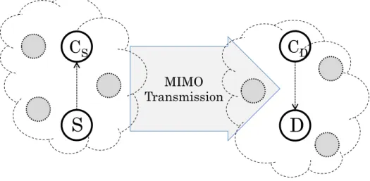
1.7 A simple cooperative MIMO system with one cooperative node at the transmission side and one cooperative node at the reception side . . . 35
2.1 System model of the MIMO precoding technique . . . 40
2.2 The virtual representation of a linear precoding system . . . 43
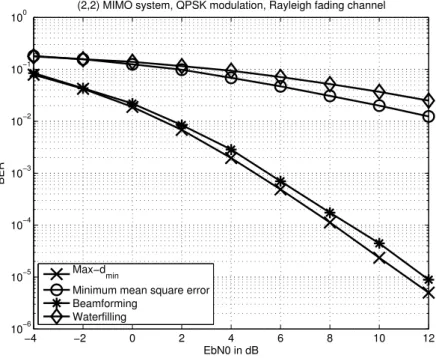
2.3 BER performance of different precoding designs . . . 50
2.4 BER performance of direct feedback and limited feedback in compar-ison to a perfect CSIT system for max-dmin precoder. . . 53
2.5 System model of a distributed precoded scheme . . . 56
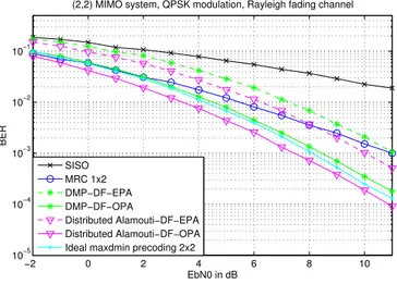
2.6 BER performance comparison: DMP vs. traditional schemes . . . 64
2.8 Total energy consumption vs. distance (10−5 BER) . . . 65
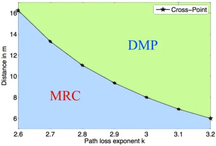
2.9 The crossing points for different path loss exponents . . . 67
3.1 Distributed scheme description with a source node, a relay node and a destination. . . 72
3.2 Illustration the correlation between d2 min and r in the hypothesis 1 (similar results for both remaining hypothesis) . . . 80
3.3 Close values of the expectations in different hypothesis. . . 81
3.4 Distribution of r1(i) in Hypothesis 1: decoding erroneously the first symbol and correctly the second one . . . 83
3.5 Distribution of r2(i) in Hypothesis 2: correctly decoding the first symbol and erroneously the second one . . . 84
3.7 BER performance comparison between simulation result, upper bound and interfering estimation method in the configuration of dSC = 5%dSD, dCD = 97.5%dSD . . . 84
3.6 Distribution of r3(i) in Hypothesis 3: decoding erroneously both sym-bols . . . 85
3.8 BER performance comparison between simulation result, upper bound and interfering estimation method in the configuration of dSC = 25%dSD, dCD = 85%dSD . . . 86
3.9 BER performance comparison between simulation result, upper bound and interfering estimation method in the configuration of dSC = 50%dSD, dCD = 60%dSD . . . 86
3.10 Power allocation parameter β0 for best performance . . . 87
3.11 DMP vs. conventional schemes . . . 88
3.12 Relay position impact on DMP performance . . . 89
3.13 Performance comparison between different ML decoders for different values of β . . . 91
4.1 Distributed scheme description with a source node, a relay node and a destination. . . 97
4.2 The pdf of d2
min for Fr1 simulation approach vs. theoretical approach.
The network is set as dSD = dCD, dSC = 5%dSD; Eb/N0 = 0dB; and
β = 0.05. The solid line denotes for theoretical results, the cross mark denotes for simulations . . . 104 4.3 The pdf of d2
octa: simulation vs. theoretical approach. The network
is set as dSD = dCD, dSC = 5%dSD; Eb/N0 = 0dB; and β = 0.05.
The solid line denotes for approximations, the cross mark denotes for simulations . . . 105 4.4 The pdf of d2
min: theoretical vs. simulation approach. The network
is set as dSD = dCD, dSC = 5%dSD; Eb/N0 = 0dB; and β = 0.05.
The solid line denotes for approximations, the cross mark denotes for simulations . . . 106 4.5 The pdf of d2
min: theoretical vs. simulation approach.The network
is set as dSD = dCD, dSC = 5%dSD; Eb/N0 = 0dB; and β = 0.25.
The solid line denotes for approximations, the cross mark denotes for simulations . . . 107 4.6 The pdf of d2
min: theoretical vs. simulation approach.The network
is set as dSD = dCD, dSC = 5%dSD; Eb/N0 = 0dB; and β = 0.5.
The solid line denotes for approximations, the cross mark denotes for simulations . . . 107 4.7 The ergodic capacity performances: comparison between the equal
and optimal power allocation, dSD = dCD, dSC = 5%dSD . . . 115
4.8 The outage probability for simulation and theoretical approximation with β = 0.5 and two values of threshold R=1; 2 bit/s/Hz; the net-work is set as dSD= dCD, dSC = 5%dSD; blue and black color denote
for the OPA and EPA, respectively; the solid line with mark denotes the simulation result, and the dash line denotes the theoretical result. 116 4.9 Values of β0 versus Eb/N0 to obtain the maximum capacity in the
context of WBAN:dSD = dCD, dSC = 5%dSD . . . 117
4.10 Sphere decoding principle . . . 124 4.11 Wake Up Radio overview . . . 125
List of Tables
1.1 List of scenarios in WBAN and their frequency band . . . 18 1.2 The AIC for the considered models, the minimum value determines
the best fitting model . . . 25 2.1 Parameter values for max-dmin precoder in 16-QAM modulation . . . 48
2.2 Spectral efficiency of different cooperative schemes with QPSK . . . . 63 2.3 Parameter values of the consumption model [20] . . . 66 3.1 Value of Nb and Nn for QPSK and 16-QAM . . . 75
Acronyms
AF Amplify-and-Forward.
AIC Akaike Information Criterion. AP Access Point.
ARQ Automatic Repeat reQuest. AWGN Additive White Gaussian Noise.
BCU Body Control Unit. BER Bit-Error-Rate.
BoWI Body World Interaction. BPSK Binary Phase Shift Keying.
CC Coded Cooperation. CF Compress-and-Forward. CSI Channel State Information.
CSIT Channel State Information at the Transmitter. CTS Clear To Send.
DF Decode-and-Forward.
DMP Distributed max-dmin Precoding.
DMPAF Distributed max-dmin Precoding Amplify and Forward.
DMPDF Distributed max-dmin Precoding Decode and Forward.
ECG electrocardiogram. EEG electroencephalogram. EGC Equal Gain Combining. EPA Equal Power Allocation.
ICT Information and Communications Technology.
LLR Log-Likelihood Ratio. LOS Line Of Sight.
LPT Local Precoded Transmission. LQI Link Quality Indicator.
LST Local Successive Transmission.
MIMO Multiple-Input Multiple-Output. ML Maximum Likelihood.
MMSE Minimum Mean Square Error. MRC Maximal Ratio Combining.
NLOS Non Line Of Sight.
OPA Optimal Power Allocation.
PAR Peak-to-Average Ratio. PDA Personal Digital Assistance. pdf probability density function. PRR Packet Received Rate. PSD Power Spectral Density.
QAM Quadrature Amplitude Modulation. QoS Quality of Service.
RF Radio Frequency.
RSSI Received Signal Strength Indicator. RTS Request To Send.
SC Selection Combining.
SIMO Single Input Multiple Output. SISO Single Input Single Output. STBC Space-Time Block Code. STTC Space-Time Trellis Code.
UWB Ultra-Wide Band.
VNA Vector Network Analyzer.
WBAN Wireless Body Area Network. WSN Wireless Sensor Network.
Notations
Cocta instantaneous ergodic capacity in the case of octa.
Cr1 instantaneous ergodic capacity in the case of r1.
C instantaneous ergodic capacity.
GCD relative distance power gain of C ! D with respect to S ! D.
GRD relative distance power gain of R ! D with respect to S ! D.
GSC relative distance power gain of S ! C with respect to S ! D.
GSR relative distance power gain of S ! R with respect to S ! D.
Gr antenna gain of reception side.
Gt antenna gain of transmission side.
Ml link margin.
Nb average of difference bits between two neighbors.
Nn average number of neighbor.
Nf receiver noise figure.
Nsr statistical variance of nsr.
PADC power consumption of analog-digital converter.
PDAC power consumption of digital-analog converter.
PIF A power consumption of intermediate frequency amplifier.
PLN A power consumption of low noise amplifier.
Pf ilr power consumption of filter at the receiver.
Pf ilt power consumption of filter at the transmitter.
Pmix power consumption of mixer.
Pocta
out outage probability in the case of octa.
Pr1
out outage probability in the case of r1.
Ppa power consumption of power amplifier.
Ptrans transmission power consumption.
Rb bit rate.
R predefined rate.
SIN R signal to interference plus noise ratio. SN R signal to noise ratio.
Γ(.) the gamma function.
Σntotal variance of total noise vector.
↵2
sr statistical variance of hsr.
β power allocation parameter.
✏ symbol error rate of local exchange phase. ⌘S spectral efficiency.
γ0 channel angle threshold.
γinc lower incomplete gamma function.
γ channel angle. ˆ
Eb needed energy per bit for a BER target.
ˆ
s detected signal of s. Fd precoding matrix.
Fv virtual precoding matrix.
Focta precoding matrix for the case octa.
Fr1 precoding matrix for the case r1.
F complete precoding matrix. Gv virtual decoding matrix.
G decoding matrix. Hv virtual channel matrix.
H MIMO channel matrix.
nc noise vector at the cooperative node.
ntotal total noise vector.
n noise vector. s transmit vector.
y received vector.
Ed the energy of second transmission phase (or precoding transmission phase).
El the energy of first transmission phase (or local exchange phase).
E the total energy to transmit one symbol. Fd set of matrices Fd for limited feedback.
Fv set of matrices Fv for limited feedback.
F set of matrices F for limited feedback. Q(.) Q function.
S modulated constellation. erfc complementary error function. φ scaling parameter of precoder.
power allocation parameter of precoder. ⇢ channel gain.
σi singular values of channel matrix in decreasing order.
θ rotation parameter of precoder. ˜
C average ergodic capacity. ˜
Pe average bit error probability.
b number of data streams.
dCD distance from the cooperative node to the destination.
dRD distance from the relay to the destination.
dSC distance from the source to the cooperative node.
dSD distance from the source to the destination.
dSR distance from the source to the relay.
dmin minimum Euclidean distance.
focta d2
min pdf of d
2
min in the case of octa.
fr1
d2
min pdf of d
2
min in the case of r1.
fd2 min pdf of d 2 min. fij entries of F. g, gi amplifying factor. hij entries of H.
hsd channel of the transmission from the source to destination.
hsr channel of the transmission from the source to relay.
h local channel.
k modulation level of QAM. nR number of receive antennas.
nT number of transmit antennas.
nrd noise at the destination of the transmission from the relay to destination.
nsd noise at the destination of the transmission from the source to destination.
nsr noise at the relay of the transmission from the source to relay.
spre precoded signal.
s signal of the source.
yrd received signal at the destination from the relay.
ysd received signal at the destination from the source.
ysr received signal at the relay from the source.
Eb energy per bit.
N0 noise power.
The Wireless Body Area Network (WBAN), consisting of multiple small wire-less sensor nodes embedded on human body, represent a remarkable milestone of personal network. This network widely enhances the quality of life not only in the entertainment industry, multimedia, sport training, military, security... but also in the medical domain, where it provides an innovative method to monitor the health more flexibly and more efficiently. As wireless communications represent the major energy consumption in the network, the objective of this thesis is to propose a high energy-efficient transmission protocol that is suitable for the WBAN.
The latter induces severe channel fading that can be counterbalanced by the diversity provided by relay and MIMO techniques. Moreover, precoding techniques are investigated to adapt the signals to be transmitted to the propagation channel. Owing to the difficulty of embedding several antennas in a small-size sensor node, the cooperation manner has to be adopted to deploy the MIMO precoding technique into WBAN. Regarding the performance, the minimum Euclidean distance based precoding is chosen due to its advantages in reducing the error probability.
In this thesis, we propose therefore the deployment of a minimum Euclidean dis-tance based precoding, called Distributed max-dmin Precoding (DMP) into WSN in general and in WBAN in particular. We will especially focus on the link be-tween the WBAN and a base station equipped with two antennas, and two relay-ing protocols are considered: Decode-and-Forward (DF) and Amplify-and-Forward (AF). By nature of the spatial multiplexing, the DMP offers higher spectral effi-ciency than a distributed Space Time Coding (STC). As far as the DMP-AF is concerned, we introduce different manners to handle the local channel that changes significantly the precoder. The latter can be designed taking into account this local channel or adapted afterwards, and we can exchange two symbols in once or con-secutively [68], [70]. The Monte Carlo simulations show out impressive performance of proposed transmission schemes in comparison to conventional scheme such as Single Input Single Output (SISO) and Single Input Multiple Output (SIMO). An energy model, taking into account the circuit consumption and transmission con-sumption, was used to compare the considered DMP and the existing protocols in terms of energy consumption. The results point out the interest of using the DMP
for medium distances between transmitter and receiver. Besides these simulations, the theoretical performance of our DMP schemes is derived. For the DF relaying, the system can be transformed equivalently to an interference system, where the appearing interference is determined to be signal-dependent. As a result, the com-bination of interference approach and the minimum Euclidean distance distribution allows adopting the upper bound for the error probability in the DMP-DF [69]. For the AF relaying, we carry out an equivalent system model, taking the local channel into account of precoding design, before the analysis on Euclidean distance distri-bution is established. Based on that, the evaluation on the ergodic capacity and outage probability are performed [70]. The performance analysis not only confirms the simulation results but also does help to allocate the power more efficiently, for both DMP-DF and DMP-AF. Moreover, in the DMP-DF, we propose new maximum likelihood decoder at the destination that improves the receiving performance [69]. This decoder considers the decoding information of relay to adjust the log-likelihood ratio, hence the decoding error is reduced.
Over the past couple of decades, the life expectancy of people has increased to a great extent due to the amelioration of science and medicine especially in the devel-oped countries [61]. This is a result of the quality of life and medical improvement through the new treatments for sicknesses as well as the advancement in technol-ogy. Accordingly people have started living longer, leading to the increasing of an aging population. This means in near future people will be facing to the overload of the health care systems. Besides the growth of health care demands for elderly people, medical researches [101] have proved that most of the diseases for instance cancers, asthma, chronic or fatal diseases, can be prevented if they are detected in their early stages. This requires a new medical treatment that allows to track the physiology data in real time. Fortunately, recent technology achievements as inte-grated circuits, wireless protocols, physiological sensors will allow us to tackle with these demands. These motivations create a new type of Wireless Sensor Network (WSN): Wireless Body Area Network (WBAN) [21, 41, 51, 72, 76]. Along with the rapid growth of micro-electronic technology, personal electronic devices are more diverse and modern. Meanwhile, a significant improvement in terms of miniatur-ization allows putting electronic devices onto/into the human body. Basically, the WBAN is a specific kind of WSN, targeted to the human body. The WBAN, which is known as a new way of doing things, does not only provide a new health care generation but also can be used in other areas such as: home entertainment, office application, sport training, and security supports...
The WBAN uses small light smart sensors placed on/in the human skin. The term ”smart” herein refers their capability to collect, process information; commu-nicate each other, and sometimes assist the medical treatment. These sensors have the task of taking the vital information to help analyzing the health situation of the object being tracked. In medicine, physiological sensors collect data of temper-ature, blood pressure, heart rate, electrocardiogram (ECG), electroencephalogram (EEG), respiration rate . . . In a conventional health care, these parameters are usu-ally obtained by medical tests that suffer many inconveniences in terms of cost, flexibility and timeliness. With the growth of aging population, the current medical system will not be able to sustain this expansion, and WBAN are seen as a potential
solution.
A WBAN provides a monitoring method that prevents patients from sudden infant death syndromes or enables proper dosing and reduces the risk of fainting for diabetes patient. In addition, data provided by WBAN is continuous, real-time and during a large-interval real-time, therefore its medical information should be more accurate and complete. Besides, WBAN also offers intelligent solution to support patients in the emergency situation or assist people with disabilities. For example, a paralyzed patient can recover the ability to move by the interaction of a sensors network that connect the nerves system and muscles of patients with an artificial actuator. The WBAN integrated within an overall eHealth solution could bring a step change in the remote management of patient healthcare. Generally speaking, there are two types of devices; sensors which are used to measure certain parameters of the human body, either externally or internally, and actuators which act as a drug delivery system according to the data they receive from the sensors or through interaction with the user. The medicine can be delivered on predetermined moments, triggered by an external source, in other words a doctor who analyzes the data, or when a sensor notices a problem. For example, if a patient suffering from diabetes has a sudden drop of glucose, a signal will be sent to the actuator in order to start an injection of insulin. In short, WBANs will be a key solution in early diagnosis, monitoring and treatment of patients with possibly fatal diseases of many types, including diabetes, hypertension and cardiovascular related disease.
Besides medical applications, the WBAN can also be found in non-medical do-mains. The first one is the real time streaming which involves video streaming, audio streaming as well as stream transfer which are used for vital sign and body information-based entertainment service, body gesture motion capture, remote con-trol of entertainment devices, identification, emotion detection and to monitor for-gotten things by sending an alert to the owner. Nexts are the entertainment appli-cations, which consist of gaming applications and social networking. The devices integrated in WBANs are appliances such as microphones, MP3-players, cameras and advanced computer. They can be used in virtual reality, personal item track-ing, exchanging digital business card, consumer electronics and gaming purposes, for
instance game control with hand gesture (such as wii’s or xbox’s games) or mobile body motion game and virtual world game. The third one is called emergency (non-medical), which are on-body sensors capable of detecting a non-medical emergency such as fire or poisonous gas to urgently warn the user in that emergency condition. Furthermore, there is the emotion detection which, via simple bio-sensors, measures the induction of physical manifestations throughout the body. The last one is called Secure Authentication; it uses both physiological and behavioral biometrics such as iris recognition, fingerprints and facial patterns. This is one of the key applications of WBANs due to duplicability and forgery, which has motivated the use of new physical characteristics of the human body.
Sensors in the WBAN are required at key positions to enable effective monitor-ing of the relevant physiological conditions. They operate cooperatively, formmonitor-ing a sensor network, which is a deployment of several devices equipped with sensors that perform a collaborative measurement process. A WBAN needs a communica-tion module that supports a wireless protocol such as wifi, bluetooth, zigbee. . . The wireless nature will not only help the network be more flexible for daily activities but also facilitate the communication to an external system such as a surveillance system, internet, and cellular networks. On the other hand, it also brings real challenges on communication reliability, security, safety, and power consumption. Given the WBAN context, this thesis focuses on the study of communication, es-pecially on energy consumption aspects. In practice, the wireless communication has to deal with more complex problems than the wired one. Firstly, the wireless channels should be subject to various unfavorable factors such as fading, shadow-ing, attenuating... Energy loss when wireless communication performed on human body is stronger due to the absorption of body tissues. Furthermore, the nature of daily application, human movement and posture changes will affect substantially the wireless channels. A further constraint on size has to be taken into consider-ation, leading to the limitation of energy source, e.g. batteries. Consequently the optimization of energy must be ultimately focused. Moreover, reducing the trans-mit power also offers the advantage in litrans-miting the interference between devices as well as networks. In addition, the safety standards on microwave power must be an
important consideration. Thereby, for wireless personal devices, the radiated waves have to be controlled to prevent the damage to the vital organs and tissues. The low power constraint allows a long life battery capability, which is a key requirement because a patient could have to undergo an operation each time of battery failure.
BoWI project: Body World Interactions [1]
BoWi is a CominLabs project, focused on the society challenge called Digital Envi-ronment for the Citizen. It is also related to the social challenge Information and Communications Technology (ICT) for Personalized Medicine and to the research track Energy Efficiency in ICT.
Figure 1: An overview of BoWI project [1]
The main objective of the BoWI project is to develop a pioneer interfaces for an emerging interacting world based on smart environments (house, media, informa-tion and entertainment systems...). The Wireless Body Areas Sensor Networks is
focused for the aim of estimating accurately the gesture and body movement. The ultimate requirements are determined on the device size and the ultra-low power consumption. In BoWI, the geolocation approach will be the combination of the radio communication distance measurement and inertial sensors data. The health care, activity monitoring, and environment control can be considered as applications of BoWI.
In the first step, the Zyggie (Figure 2) prototype was developed as a wearable device. Three sensors are integrated inside: the accelerometer, gyrometer, and magnetometer. The project’s initial task is to use the data from these sensors to detect the posture. To do so, Zyggie nodes will be set on a specific location then transmit its data to the station. This station gathers and analyzes data then gives out the posture/gesture. This thesis’s objective is to propose a high energy efficient wireless communication protocol that is suitable for BoWI project.
Figure 2: Zyggie prototype, version 1
Within BoWI, four works are proposed to be investigated. The first one is aiming to design an ultra-low power architecture for WBAN. The configurable architecture is considered and the ultra-low power can be achieved by the aggressive use of dy-namic power management [1]. On another aspect, the antenna and propagation are tackled. The objective is to obtain the channel models of WBAN by measurements, and afterwards use them in order to design an antenna that is suitable for the Zyggie prototype. In addition, a work on the multi-sensor and radio based geolocation is carried out. The aim is to propose an algorithm that exploits effectively the data of inertial sensors (magnetometer, accelerometer, and gyroscope) to detect the user’s gesture. In the next step, the Ultra-Wide Band (UWB) geolocation can be studied for more accuracy and probably more energy efficiency.
This thesis is in charge of the wireless communication which is the key factor connecting devices in BoWI project. The ultimate objective is to reduce the power consumption meanwhile maintain the reliability. To manage these requirements, the spatial diversity is a good approach to study. However, the size constraint of WBAN cannot allow to equip multiple antennas to deploy the spatial diversity. For this reason, the cooperative technique is proposed to be investigated. In fact, this technique is already well-studied in the WSN context, and exists almost in two main categories: cooperative relay and cooperative Input Multiple-Output (MIMO). Our contribution is to go in deep on the implementation of a MIMO precoding into the WBAN via the cooperative technique. In this term, we set an eye on the minimum Euclidean distance based precoding with an impressive performance in reducing the error probability.
Thesis contributions
− Thanks to measurements on the channel characteristics for BoWI prototype (Zyggie), the nature of channel fading in WBAN is analyzed. The distribution fitting process is carried out to obtain the suitable model for the considered system.
− With the aim to obtain a high energy efficient network, we focus on the wire-less communication protocol. As a result, we have proposed and investigated the distributed precoding scheme, based on the cooperative deployment of a minimum Euclidean distance precoder. Two forwarding strategies are consid-ered: Decode-and-Forward and Amplify-and-Forward. In terms of DMP-AF, we introduce different uses of signal processing in the local exchange phase. The numerical evaluation (Matlab simulation) pointed out the outperformance of the proposed protocol compared to the conventional system such as SISO, MISO, distributed Space-Time Block Code (STBC) in terms of error rate, or energy efficiency. An energy model has been studied for the DMP scheme, the comparison to conventional schemes is derived afterwards. Thereby, the energy consumption is in favor of the DMP for medium distances (several
meters).
− As far as DMP-DF is concerned, the performance analysis approach is carried out based on the classification of hypothesis, occurring in the cooperative node when decoding. As a result, an equivalent system is presented with the appearance of the interference. The upper bound on the error probability is then achieved. Based on that the power allocation can be accomplished. − If the decoding information at the cooperative node is available at the
desti-nation, an advanced Maximum Likelihood (ML) decoder will be performed, taking the decoding error of cooperative node into the computation of Log-Likelihood Ratio (LLR). In expense of higher complexity, the new decoder offers significantly a performance improvement.
− Regarding the DMP-AF, to obtain the performance analysis, we transformed the system model to achieve the corresponding system. The spectral-advantageous AF scheme was picked up, then the distribution of minimum Euclidean dis-tance was investigated. Afterward, some evaluations were derived, based upon the probability density function (pdf) of dmin such as: ergodic capacity and
outage probability. We performed the power allocation analytically, aiming to maximizing the system capacity.
Thesis structure
Chapter 1: Communication in WBAN
Aiming to develop a network that is easily deployable on human body, the wireless communication is an important requirement, but it suffers from the effects of the channel such as path loss, fading, shadowing... In WBAN these factors are even more particular due to the nature of human body environment and the mobility induced by the daily activities (walking, running, standing...). Thus, in this chapter a view on the elements that affect the wireless communication will be described. Regarding the existing communication protocols, a literature review will be provided on well-known cooperative protocols, such as cooperative relay and cooperative MIMO.
Chapter 2: How to benefit from channel feedback
Looking at the MIMO categories, the precoding technique emerges as a closed-loop system that can use the channel feedback efficiently. Moreover, by nature of a spatial multiplexing system, this technique achieves an impressive spectral efficiency, compared to the STBC. More advantageously, the feedback information can be exploited to satisfy a pertinent requirement such as: Minimum Mean Square Error (MMSE), equal-error, Quality of Service (QoS), SNR-maximization, maximization of capacity...
An overview of MIMO precoding techniques is introduced in this chapter, and the idea to bring the MIMO precoding into the WSN via the cooperation manner is tackled. In this latter work, we mention an application of a minimum Euclidean distance based precoding with the huge advantage in diminishing the error rate. The numerical evaluation on the performance and energy efficiency is also provided. Chapter 3: Distributed maxdmin precoding: Decode and Forward
In this chapter, we specifically consider the Decode-and-Forward structure. We address the performance analysis of the distributed precoding scheme, deploying the Euclidean distance based precoding via cooperative technique in a general WSN; the implementation into WBAN is totally similar. The decode-and-forward relaying is focused on the basic case with one single relay node, one source node and a destination which possesses two co-located antennas. The given methodology in this chapter, is obviously extendable for larger systems. These extensions might be considered in the future works with more relay nodes and/or more antennas at the destination.
In addition, we propose to examine the possibility to use the information of the relay performance at the destination. This information is adopted in calculating the log-likelihood ratio to detect more efficiently the symbol in the maximum likelihood (ML) decoder at the destination. A new maximum likelihood decoder is introduced, exploiting the decoding error probability of the relay to enhance the detection at the destination. In the light of the fact that the complexity of ML decoder augments severely in a full use of this information, we propose a suboptimal and less complex
solution taking advantage of the max-log approximation.
Chapter 4: Distributed maxdmin precoding: Amplify and Forward Similarly to the previous chapter, the Amplify-and-Forward scheme performance analysis is derived, to further obtain the practical power allocation. The Local
precoded transmission with the channel customizing scheme will be selected due
to its spectral efficiency and performance. The theoretical performance analysis on the channel capacity and outage probability are carried out, based upon the statistical distribution of minimum Euclidean distance between two received vectors. We address out also the power allocation strategy, defining the power apportionment between two phases of a distributed scheme that offers the best channel capacity performance.
Chapter 1
Introduction
The WBAN can be consider as a specific type of WSN where the devices, network topology, communication scenarios are different. Aiming to develop a network that is easily deployable on human body, the wireless property is an important requirement. The communication in WBAN therefore is carried out via the wireless channel. Unlike the wire communication, the wireless communication suffers from affects of the channel such as path loss, fading, shadowing... Especially, in WBAN these factors are more particular due to the nature of human body environment.
In WBAN, one of most important constraint is the ultra-low power consump-tion. Regarding this term, two components are considered: circuit and transmission consumption. Like other electronic system, the components such as processor, am-plifier, mixer, filter... consumes the energy for signal processing. In recent years, the explosive growth of micro-electronic technology empowers the processing capability while reduces the power consumption. This positive trend offers more opportunity to obtain a flexible, powerful WBAN with small size and long-term operation. The second kind of power consumption is due to wireless wave propagation. According to the nature of wireless, we emit wirelessly an electromagnetic wave to create the communication among devices. The energy consumed by this operation depends on the physical algorithm, environment, frequency band, etc. In the light of the fact that the consumption of the circuit is more and more diminished along with the semiconductor technology advancement, the transmission takes an important part in the energy diagram. For this reason, to propose an ultra low power wireless net-work, it is obvious to focus on the wireless communication. In general, the wireless communication is more complicated than the wire one owing to the sophisticated channel. Especially in WBAN, this issue becomes more difficult due to the human body is not an ideal media for radio frequency propagation.
Consequently, in this chapter a view on the elements of a WBAN is provided including the description of the wireless communication aspects in section 1.1. Af-terwards, the state of the art of cooperative technique that is capable to reduce the transmission power, is described in section 1.1.2. Section 1.3 finally concludes the
(a) Star topology
Center node Sensor node
(b) Cluster tree topology
Figure 1.1: Two common topologies used in WBAN
chapter.
1.1
Overview on WBAN
1.1.1
WBAN architecture
1.1.1.1 Network topology
Generally, the WBAN can be organized as a star, cluster tree, mesh or ring topology. However, the two former topologies star and cluster tree are used most commonly in WBAN. Star topology (see Figure 1.1a) is suitable for applications supported by small network, whereas cluster tree (see Figure 1.1b) one is more convenient for larger scale physical size network. Obviously, the star topology is well suitable for WBAN due to the dimensions. All nodes in network are connected to a central coordinator (center node), this node responds to gather, process, and forward the data to an access point that is capable to analyze them. Consequently, the center node in this topology is supposed to be more powerful in terms of energy, processing capability, and memory than the other nodes in the network.
1.1.1.2 Types of devices
1. Sensor node: This device is mounted on the body. All information such as vital signal, location data, environment condition, audio, video signal. in WBAN is recorded by this device. Additionally, a sensor node must be capable to do some simple signal processing and transmit wirelessly the data to an external access point [4]. Two kinds of sensor node are existing: implant and on-body sensor. Most of implant nodes are used in medical application to monitoring the vital signal, whereas on-body nodes can be used for both medical or non-medical application.
2. Actuator node: In general, an actuator node is similar to a sensor node (also on-body device), except it is able to execute some particular task according to the information it receives or the order from external access point [48]. 3. Personal access point: This device responds to gather all data in a network
then forward to the external access point, located far away from human body. In some cases, it is used to inform user for warning or providing information. Basically, a personal access point acts like a center node in a WBAN. As a result, it is more powerful than the other node in terms of processing capability, memory, energy resource [86]. In some applications, the smart phone or the Personal Digital Assistance (PDA) can be personal access point.
4. External access point: This device is the center of the network, it undertakes the analysis of all data received from the sensors, and keeps them for the future needs. It can also take decisions or make the data available on the internet. 1.1.1.3 Transmission scenarios
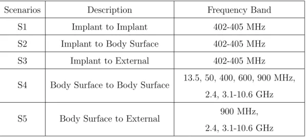
The potential of WBAN is evident, it is still in the early time of development. Therefore, the subgroup IEEE 802.15.6 was formed, aiming to develop WBAN for medical and non-medical devices. In summary, four main scenarios are listed by this standard in the Table 1.1 [105]:
Scenarios Description Frequency Band S1 Implant to Implant 402-405 MHz S2 Implant to Body Surface 402-405 MHz S3 Implant to External 402-405 MHz
S4 Body Surface to Body Surface 13.5, 50, 400, 600, 900 MHz, 2.4, 3.1-10.6 GHz S5 Body Surface to External 900 MHz,
2.4, 3.1-10.6 GHz Table 1.1: List of scenarios in WBAN and their frequency band
magnetometer. The data from these sensors, combined with Received Signal Strength Indicator (RSSI) information is collected by an external Access Point (AP) (com-puter). This AP is supposed to be a powerful station with outstanding capability in terms of processing, memory and energy. Therefore, two transmission scenarios are concerned to be studied herein. The first one is the communication among on-body nodes in a WBAN, called intra-BAN. This scenario is crucially affected by human body, the surround environment as well as the gesture. The second scenario is the communication between the center node and the AP. This kind of communication is called: extra-BAN.
1.1.1.4 Intra-BAN communication
For the reason that WBAN is a small network, the star topology is advantageous. Consequently, there is only the connection between the center node and sensor nodes (sensor nodes do not communicate to each other). The most important constraint on this communication is the simplicity, not only to reduce energy consumption and delay time but also because the distance between two nodes is small. A simple direct transmission SISO is an obvious possibility. This is the simplest way to transmit a signal, therefore we drain less energy for the circuit. However the drawback is that to obtain a sufficient performance, we emit a significant power. Besides, the multi-hop transmission could be considered. This protocol is used popularly in a
tree or cluster-tree topology. For example, in [49] a cascading multi-hop scheme proposes low delays, low packet loss and high energy efficiency while the flexibility is preserved. In another study [82], a scheduling provides multihop support through the division of the network into timezones. Thanks to this, a shortest path routing from a node to the gateway is obtained.
In addition, the gesture and human movement have important impact on the channel properties and the path loss. Adapting the transmission protocol with the change of the gesture provides the opportunity to enhance the link quality and reduce the energy consumption. For example, in [29] a packet transmission scheduling is addressed, based on the behavior of RSSI between transmitter and receiver. Thanks to some periodical movement of the human body, this protocol predicts the peak in the RSSI diagram to send packets. As a result, the Packet Received Rate (PRR) between 50% and 90% of an outdoor intermediate link is increased to above 90%. Moreover, a power control mechanism can be used to manage the transmit power in function of the link quality [44, 80]. Specifically, based on the information about RSSI/Link Quality Indicator (LQI), the transmission power is adapted to prevent the energy waster in the case the link is strong and assure the link reliability when the link goes bad. Furthermore, the power control can also be deployed using the knowledge of body posture on the transmission.
Figure 1.2: Two categories of communication in WBAN: red dash arrow denotes the intra-BAN and green solid arrow denotes the extra-BAN
Instead of using radio frequency wave to transmit the signal, the human body can be used as a transmission medium for electrical signals [107], call intra-body
communication. Therefore, the body becomes a channel to perform a coupling
between transmitter and receiver. In general, we can classify the coupling of intra-body communication into 2 main categories: capacitive coupling [23,24,27,77,78,107] and galvanic coupling [28, 50, 71]. In the first method the use of the near field and the capacitive coupling of human body to its environment make the human body acting as a transmission medium. Whereas, the latter method exploits the coupling current into human body via two electrodes. This intra-body coupling proposes an ultra-low power transmission, benefiting from the utilization of dielectric body parameters to send the data. In contrast, its drawback is that he data rate is limited and the system is less convenient due to the requirement of direct contact of sensor node and human tissue.
1.1.1.5 Extra-BAN communication
The requirement of sending out the data to the external station makes the extra-BAN communication happening (see Figure 1.2). The extra-extra-BAN is defined as the communication between a node in WBAN and an external AP. In WBAN, there is a center node responds to gather and send out all data in the network. Different to the intra-BAN communication, the channel in extra-BAN communication is less particular. It can be considered similarly as the context of cellular network or any personal device network. Basically, the direct transmission SISO and multi-hop technique are applicable. Nonetheless, the demand on a low-power system make them less feasible due to the reason that they require significant power to obtain a sufficient performance. On this aspect, the MIMO is considered as a good candidate in proposing the spatial diversity to increase the performance with the same power level as the conventional protocols. However, the constraint on the physical size of sensor node limits this spatial diversity technique (the most feasible diversity technique) to enhance the communication quality. To overcome this challenge, the need of cooperation is obvious [11]. This technique exploits the help of one or multiple additional nodes to create the spatial diversity. We provide the state of the
art on the cooperative technique in the section 1.2.
1.1.2
WBAN channel characteristics
In order to deploy the wireless communication, the obligation is to investigate the wireless channel, in which the electromagnetic wave is propagated. To study the physical layer, the channel model, consisting of characteristics such as path loss, fading, shadowing, power delay profile..., is required. In this section, we discuss some typical characteristics of propagation channel in the WBAN.
1.1.2.1 Body tissues
The human body, in general, got many characteristics that influence on the radio frequency propagation such as conductive factors, dielectric constant, impedance... As a result, the wireless transmission suffers high losses caused by the power ab-sorption, frequency shift, radiation pattern destruction... The effects are obvious, however the variation of human tissue characteristics (owing to the different body size, sex, age, fat percentage. . . ) makes the investigation more complicated.
1.1.2.2 Antenna effect
Basically, human body possesses strong dielectric characteristic, thus it affects sig-nificantly on the antenna radiation pattern. Moreover this characterization varies with different individual body, causing the difficulty in being described in a unique manner. The change of human gesture and posture affect also the propagation na-ture of antenna. Therefore, it is obliged to understand all these aspects to adapt the wireless communication into body area environment. In addition, the antenna design is strongly depending on the application of WBAN. That means the form, the size, and the characteristic of antenna must be suitable with the purpose and situation. For example, for the on-body node, the dipole antenna might be suitable, whereas, in pacemaker implant, the circular antenna might be selected. In conclu-sion, the antenna design must take into account the dielectric elements of human body tissues as well as the application in which it is being used.
1.1.2.3 Path loss
Regarding the extra-BAN links, the path loss is easily modeled as a distance-dependent model. In other words, this link is totally similar to other classical systems such as cellular network, multimedia communication, wifi communication... Unlikely, the intra-BAN links propose the complicated attenuation behavior. The reason is not only the sophisticated absorption of body tissues (due to different tissue characteristics: body size, sex, age. . . ), but also the continuous gesture that changes in daily activities. The attempt to model the path loss in function of sepa-rated distance is poorly suitable [58, 92]. A path loss model must take into account not only the distance, but also the sensor placement and human movement.
1.1.2.4 Fading
Due to many reasons, the wireless signal in WBAN is faded. The fading phenomenon might be created by the multipath of surround environment, the energy absorption, the reflection, or the shadowing of body parts. The fading causes the deviation of the attenuation affecting the received signal. In a wireless system, the principle of the fading behavior must be determined in order to evaluate a certain trans-mission protocol. In literature, there are some studies on modeling the statistical channel distribution [92, 93] , [85], [22], [91], [18] for WBAN. These investigations attempted to fit the measured or simulated data of the channel gain with the fading distributions such as Rayleigh, Ricean, lognormal, Weibull... Generally, the on-body channel can be modeled as a lognormal fading in most of cases. Besides, the Weibull or gamma distribution can be listed for providing the quite good fitting. Two well-known distributions Rayleigh or Nakagami seems to be poor-fitting in the context of WBAN. Regarding the indoor environment, the most applicable case for the WBAN, the Weibull and gamma distribution are two best candidatures.
On attempting to study the characteristics on the fading property which crucially affect the wireless communication, we carry out some measurements on the on-body channels. These measurements are implemented with the Zyggie prototype [1], with the help of the Vector Network Analyzer (VNA). The environment is supposed to be indoor. Two scenarios will be focused: 1) extra-BAN : between a node on the chest
and an external node; 2) intra-BAN : between a node on the chest and a node on the wrist. The channel gain will be recorded by the VNA at 2.45 GHz. To determine the best-fitting fading distribution, the minimum Akaike Information Criterion (AIC) is applied [3]. This parameter is computed based on the data of 1000 channel gains collected in each scenarios. The following models (with their pdf) will be selected to be examined: 1. Lognormal f (x|µ, σ) = 1 xσp2⇡e −(ln(x)−µ)2 2σ2 (1.1) 2. Gamma f (x|a, b) = 1 baΓ(a)xa−1e −x b (1.2) 3. Weibull f (x|a, b) = x b2e −x 2b2 (1.3) 4. Rayleigh f (x|b) = x b2e −x 2b2 (1.4) 5. Nakagami-m f (x|m, Ω) = 2m m Γ(m)Ωmx 2m−1e−mx2 Ω , (1.5)
where Γ(.) is the gamma function. Thereby, the AIC is expressed as AIC =−2 ln(l(ˆδ/data)) + 2Z + 2Z(Z + 1)
nδ− Z − 1
, (1.6)
where ln(l(ˆδ/data)) denotes the maximum log-likelihood over unknown parameters δ, given the data and the model; Z is number of parameters in the model; and nδ is
number of sampling data.
In Figure 1.3, the distribution fitting for the extra-BAN channel is illustrated. As we can see for the case of Line Of Sight (LOS), the channel varies slightly. In this situation, the Rayleigh fading proposes the worst fitting. The best candidates would be lognormal or gamma fading. If the LOS can not be performed, the channel gain deviation becomes stronger, and the fading behavior changes. At this point, the Weibull can be the best-fitting distribution. The lognormal and gamma fading
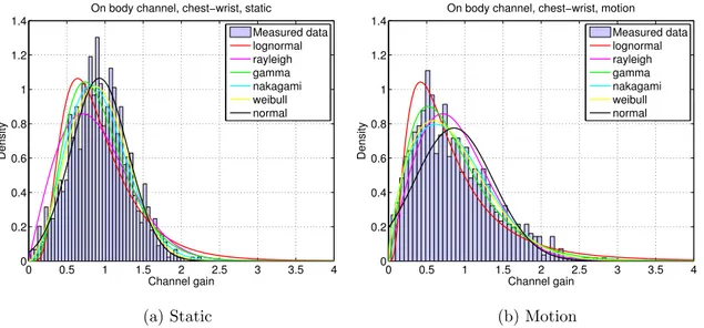
are probably considered as a good model for this channel. In intra-BAN, for a communication between the chest and the wrist, the transmitter is placed on the chest, the receiver is on the wrist. Two situations are studied: the body stands still, and the body moves. As can be seen in the Figure 1.4, the lognormal, Weibull, gamma and Nakagami fading can be the candidates.
0.7 0.8 0.9 1 1.1 1.2 1.3 0 1 2 3 4 5 6 7 8 9 Channel gain Density
On−off body channel, LOS
Measured data lognormal rayleigh gamma nakagami weibull normal
(a) Line of sight
0 0.5 1 1.5 2 2.5 3 3.5 4 0 0.2 0.4 0.6 0.8 1 1.2 1.4 Channel gain Density
On−off body channel, NLOS
Measured data lognormal rayleigh gamma nakagami weibull normal
(b) Non line of sight
Figure 1.3: The distribution fitting for the extra-BAN channel: the transmitter on the chest and receiver on the external
0 0.5 1 1.5 2 2.5 3 3.5 4 0 0.2 0.4 0.6 0.8 1 1.2 1.4 Channel gain Density
On body channel, chest−wrist, static
Measured data lognormal rayleigh gamma nakagami weibull normal (a) Static 0 0.5 1 1.5 2 2.5 3 3.5 4 0 0.2 0.4 0.6 0.8 1 1.2 1.4 Channel gain Density
On body channel, chest−wrist, motion Measured data lognormal rayleigh gamma nakagami weibull normal (b) Motion
Figure 1.4: The distribution fitting for intra-BAN channel: the transmitter on the chest and receiver on the wrist
Table 1.2: The AIC for the considered models, the minimum value determines the best fitting model
Model AIC extra-BAN LOS extra-BAN NLOS intra-BAN static intra-BAN motion Lognormal 0.1972 5.9700 5.5158 6.1649 Gamma 0.9245 5.2522 4.9686 5.3265 Weibull 0.3789 5.2198 4.8763 5.3203 Rayleigh 2.6203 3.2037 2.9805 3.3492 Nakagami-m 0.2029 5.2198 4.8933 5.3255
To determine the best-fitting model, the table of AIC for each model is provided (see table 1.2). Based upon that, we can select the lognormal for the extra-BAN channel with LOS and the Rayleigh fading for the remaining cases.
1.2
Cooperative technique
The demand on high data rate communication or less energy consumption leads to the use of some diversity techniques that provide multiple versions of data helping to enhance the transmission quality. The diversity techniques can be classified into three main categories: frequency diversity, time diversity and spatial diversity. The latter technique that exploits the space by using typically multiple antennas, is most commonly used. The data, transmitted by different paths, is therefore assured to be more reliable than a single path with the direct transmission SISO. In a co-located point to point system, the spatial diversity is obtained thanks to a MIMO technique, where each terminal could be equipped by multiple antennas. However, in WSN (WBAN in particular), the sensor size constraint does not allow to put two or more antennas on a sensor, so a classical MIMO technique could not be directly applied. Thus, to perform the diversity technique, the cooperative technique can be carried out.
1.2.1
Cooperative relay
The cooperative relay is the well-known cooperative technique in the early time. This technique is first introduced by E.C. van der Meulen [102], using a relay to assist the transmission between a transmitter and a receiver. Afterward, many works have studied its achievable advantages [19], [47], [88], [89]. In principle, the relay system is described in the Figure 1.5. Whereby, it consists of one or multiple relays that forward the signal from the source to the destination. Based on the signal processing at relays, some categories could be listed: Decode-and-Forward (DF), Amplify-and-Forward (AF), Compress-and-Forward (CF), Coded Coopera-tion (CC). The advantage of a relaying technique is to enhance the diversity since the destination receive two or more versions of information from the source and from relays. Consequently, the transmission quality (such as error rate, outage probabil-ity, channel capacity. . . ) is improved. Thanks to this, the energy consumption is decreased for a target quality requirement.
To deploy a relaying system, two main bases are considered: repetition-based and Distributed Space-Time Coding (DSTC)-based. In the repetition-based relaying, re-lays receive the information from the source, they forward afterward identically that information to the destination. The received information at the destination thereby includes different versions from independent paths (relays and source). Therefore, the probability that the destination fails to detect the signal is reduced. Whereas, the DSTC-based relaying benefits from the space time coding protocol to obtain the quality enhancement.
The cooperative relay technique can be realized in many areas: cellular network, ad-hoc network, satellite communication, radio media and WSN. Different from the other systems, a WSN in general and a WBAN in particular, is restricted by many constraints, especially in terms of size, and energy source. Due to the small-size, each sensor can be equipped only with a single antenna. Thus, in order to obtain the uniformity and the consistence with our context, from this moment we focus only on the node with single antenna . Whereas, the center AP can be supposed to be a robust station. That means the constraint in terms of computation and power could be ignored. Furthermore, two or more antennas could be equipped on AP
S
R
1D
R
2R
nFigure 1.5: Relaying system model with source S, destination D and n relays R1..Rn
that supports facilitating the space diversity in the reception side.
We consider a simple relaying system with a source node, a relay node and a destination (see Figure 1.6a). The role of relay is to help forwarding the signal from the source to destination. The transmission in a relaying system consists of two phases. In the first time-slot, the source transmit its data to both relay node and the destination. The destination buffers the data from the source and waits for the second version of it in next time slot. In the second time slot, the relay node after receiving the data from source node, will forward it to the destination. At the desti-nation, two versions of data are obtained, afterward some techniques of combination can be used such as Selection Combining (SC), Maximal Ratio Combining (MRC), Equal Gain Combining (EGC) [12]...
Let us define dSR, dSD, dRD the distances from S ! R, S ! D, R ! D,
respec-tively. Due to the difference in distance, the transmission links S ! R and R ! D obtain gains GSR, GRD in power in respect with S ! D link. Considering that
these gains depend on the path loss environment, let K be the path loss exponent. The mentioned gains are expressed as
GSR = ✓ dSD dSR ◆K , (1.7) GRD = ✓ dSD dRD ◆K . (1.8)
Owing to existing of two transmission phases, the power allocation must be regarded. To be fair, let us defineE the total energy to transmit one symbol. This energy will be divided into two parts: El, and Ed for first and second time slot, respectively.
1.2.1.1 Decode and Forward relaying
In DF relaying, the relay detects the received signal from the source then re-transmits the detected signal to the destination. Let s be the signal from the source, in the first time slot the relay and the destination receive, respectively:
ysr = p ElGSRhsrs + nsr, (1.9) ysd = p Elhsds + nsd, (1.10)
where hsr denotes the source to relay channel, hsd denotes the source to destination
channel; nsr, nsd are the Additive White Gaussian Noise (AWGN) at the relay and
destination, correspondingly.
S
R
D
d
SRd
RDd
SD (a) Decode-and-ForwardS
R
D
d
SRd
RDd
SD (b) Amplify-and-ForwardS
R
D
d
SRd
RDd
SD (c) Compress-and-ForwardFigure 1.6: Three common types of relaying: dashed arrow denotes the first time slot, the solid arrow denotes the second time slot
In the second time slot, after receiving the signal from the source node, the relay node uses the ML decoder to detect it. The detected signal ˆs then is resent to the destination through the channel hrd. The received signal at the destination is:
yrd=
p
EdGRDhrdˆs + nrd, (1.11)
where nrd denotes the AWGN in this phase at the destination. From two versions
of data from source and from relay, a MRC scheme is supposed to be utilized. The combined signal is expressed as
ycom= ysdh⇤sd+ yrdh⇤rd=|hsd|2s +|hrd|2ˆs + nsdh⇤sd+ nrdh⇤rd, (1.12)
where|.|⇤ denotes the complex conjugate. Apparently, two possibilities happen: the
relay node decodes s correctly, meaning ˆs = s, or wrongly ˆs 6= s. As a result, in the case the link between source and relay is good, the DF relay improves the performance at the destination, with respect to a single direct transmission. In contrast, if the signal is decoded imperfectly, it will affect the MRC.
1.2.1.2 Amplify and Forward relaying
In general, this technique is similar to the previous technique. However at the relay node, the signal is not decoded. Instead, it is amplified then retransmitted to the destination (see Figure 1.6b). Depending on the availability of the channel information at the relay, it can choose one corresponding amplifying factor among the cases as follows:
− If, at the relay, the instantaneous Channel State Information (CSI) is not present, except its statistical parameter, the amplifying factor is given as [38]
g = s Ed ElGSR↵2sr+ Nsr , (1.13) where ↵2
sr is the statistical variance of the channel hsr, and Nsr denotes the
noise variance at the relay node in the transmission from the source node. Using this amplifying factor, the average energy is balanced, whereas the in-stantaneous power might exceed or fall behind the average value.
− In the case the CSI is known at the relay, we can use the following amplifying factor [39] g = h ⇤ sr |hsr| s Ed ElGSR↵2sr+ Nsr . (1.14)
− Also in the case the relay is capable to obtain the channel coefficient, it uses the amplifying factor:
g = h⇤sr |hsr| s Ed ElGSR|hsr|2+ Nsr , (1.15)
to assure the output power at the relay is always controlled [5]. Therefore, the destination will receive the signal from the relay as
yrd=
p
gEdGRDhrds + nrd. (1.16)
The combining scheme is performed the same way as the DF relaying. Apparently, the noise at the relay is also amplified along with the signal. However, two versions of data are obtained at the destination. The diversity is consequently enhanced, helping improving the detection at the destination.
1.2.1.3 Compress and Forward relaying
Totally corresponding to the name, this technique compresses the data at the relay, then forward it to the destination. This idea is first introduced in [19]; instead of retransmitting a replica of the signal, we can consider quantizing and sending it as a sequence of bits. Thanks to this, the relay observation could be reconstructed at the destination.
In CF relaying [33], [90], the source node sends a message which is encoded into n symbols: s(1), ..., s(n). The relay therefore receives
ysr(i) = hsrs(i) + nsr(i). (1.17)
In order to aid the transmission between source and destination, the relay node encodes its received signal ysr into sr. This encoded message is built successively,
meaning sr(i) is constructed by ysr(1), ..., ysr(i− 1). At the destination, the received
signal could be expressed as
yd(i) = hsds(i) + hrdsr(i) + nd(i), (1.18)
where nd denotes the AWGN at the destination. Then the decompression is
per-formed at the destination with the aim to model the signal from relay and from source as a reconstructed relay observation.
In conclusion, each kind of relaying, in practice, will be suitable for a certain network configuration. Given that the link between the source and destination is weak, whereas relay offers a reliable path. The DF relaying, in this case, takes the advantage since the detection at the relay proposes very few errors. In contrast, when the link between source and relay does not allow to decode the signal properly, the CF or AF scheme can be selected.
1.2.2
Opportunistic relay
By creating the cooperation between the source and relay node, relaying techniques will suffer from the inter-node propagation channel. This effect degrades the perfor-mance comparing to a co-located system with the same diversity technique. More-over, regarding the network, there are many nodes operating simultaneously but all of them can not participate at the same time to cooperate with source node. This leads to the idea, called opportunistic relaying, to select the more suitable nodes in network to aid the communication between source and destination node [9]. It is considered as an advanced relaying technique. Therefore, it can be combined with all kinds of relaying DF, AF or CF. To select the relay nodes, two main approaches are proposed: with or without the feedback from the destination.
1.2.2.1 Without feedback selection
This technique of selection does not require the channel information from the des-tination. In other words, it is open loop opportunistic relay. Thereby the relay is chosen, based on the simple information from preamble phase, geographic
char-acteristic, residual power source... Herein, we present some well-known selections technique without the feedback from the destination.
Simple relay selection :
In [7], the authors describe a relay section based on the instantaneous SNR information at the source node among all its possible relays in the network. Hereby, all nodes will decode the signal from the source, and decide if they will be in the possible relay set. This decision is addressed out based on the correct detection of its received signal. In this set, the source then determines the relay that proposes the strongest SNR.
Power-aware relay selection :
The power-aware relay selection aims to extend the network lifetime [13]. Specifi-cally, the optimal power allocation will be applied to determine the optimal transmit power at the potential relays and source. The source then calculates the timeout based on this transmit power and the residual power on each node, and a node is decided to be the relay so that the network lifetime is maximized.
Geographic based relay selection :
As the name of this technique, the relay selection is based on the geographical in-formation of the network [104]. Thereby, the distance between the nodes is assumed to be available. Then to determine the best relay, the source derives a minimization of a metric which is computed in function of the distances and modulation scheme. The objective is to maximize the cooperation gain, thus reduce the error rate at the destination.
CSI-timer mapping relay selection In this method [9], the channel infor-mation is deduced by the received Request To Send (RTS), or Clear To Send (CTS) sequences at the potential relays. Afterward, an initial timer value is set in function of the source - relay and relay - destination channel. A node which has the timer reaches to zero first, is selected. When a node knows its timer expires first, it broad-casts a flag packet to claim itself as the relay for the source. The remaining nodes
![Figure 1: An overview of BoWI project [1]](https://thumb-eu.123doks.com/thumbv2/123doknet/11593643.298855/28.892.201.741.515.933/figure-an-overview-of-bowi-project.webp)